Page 3186 of 4500

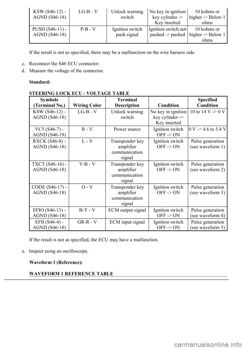
If the result is not as specified, there may be a malfunction on the wire harness side.
c. Reconnect the S46 ECU connector.
d. Measure the voltage of the connector.
Standard:
STEERING LOCK ECU - VOLTAGE TABLE
If the result is not as specified, the ECU may have a malfunction.
e. Inspect using an oscilloscope.
Waveform 1 (Reference):
WAVEFORM 1 REFERENCE TABLE
KSW (S46-12) -
AGND (S46-18)LG-B - VUnlock warning
switchNo key in ignition
key cylinder ->
Key inserted10 kohms or
higher -> Below 1
ohms
PUSH (S46-11) -
AGND (S46-18)P-B - VIgnition switch
push signalIgnition switch not
pushed -> pushed10 kohms or
higher -> Below 1
ohms
Symbols
(Terminal No.)
Wiring Color
Terminal
Description
Condition
Specified
Condition
KSW (S46-12) -
AGND (S46-18)LG-B - VUnlock warning
switchNo key in ignition
key cylinder ->
Key inserted10 to 14 V -> 0 V
VC5 (S46-7) -
AGND (S46-18)R - VPower sourceIgnition switch
OFF -> ON0 V -> 4.6 to 5.4 V
RXCK (S46-8) -
AGND (S46-18)L - VTransponder key
amplifier
communication
signalIgnition switch
OFF -> ONPulse generation
(see waveform 1)
TXCT (S46-16) -
AGND (S46-18)Y-B - VTransponder key
amplifier
communication
signalIgnition switch
OFF -> ONPulse generation
(see waveform 2)
CODE (S46-17) -
AGND (S46-18)O - VTransponder key
amplifier
communication
signalIgnition switch
OFF -> ONPulse generation
(see waveform 3)
EFIO (S46-13) -
AGND (S46-18)B-Y - VECM output signalIgnition switch
OFF -> ONPulse generation
(see waveform 4)
EFII (S46-4) -
AGND (S46-18)GR-R - VECM input signalIgnition switch
OFF -> ONPulse generation
(see waveform 5)
Page 3191 of 4500
Fig. 20: Identifying Waveform 5
Courtesy of TOYOTA MOTOR SALES, U.S.A., INC.
3.CHECK ECM
Fig. 21: Checking ECM
Courtesy of TOYOTA MOTOR SALES, U.S.A., INC.
a. Disconnect the E2 and E4 ECM connectors.
b. Measure the voltage and resistance of the wire harness side connectors.
Page 3192 of 4500
Standard:
ECM CONNECTORS - VOLTAGE AND RESISTANCE TABLE
If the result is not as specified, there may be a malfunction on the wire harness side.
c. Inspect using an oscilloscope.
Waveform 1 (Reference):
WAVEFORM 1 REFERENCE TABLE
Symbols
(Terminal No.)
Wiring Color
Terminal
Description
Condition
Specified
Condition
IMI (E2-6) - E01
(E4-2)GR-G - W-BSteering lock ECU
input signalNo key in ignition
key cylinder ->
Key insertedPulse generation
(see waveform 1)
IMO (E2-7) - E01
(E4-2)GR-R - W-BSteering lock ECU
output signalNo key in ignition
key cylinder ->
Key insertedPulse generation
(see waveform 2)
E01 (E4-2) - Body
groundW-B - Body
groundGroundAlwaysBelow 1 ohms
TerminalIMI - GND
Tool Setting10 V/DIV., 500 ms/DIV.
ConditionNo key in ignition key cylinder -> Key inserted
Page 3194 of 4500
Fig. 23: Identifying Waveform 2
Courtesy of TOYOTA MOTOR SALES, U.S.A., INC.
1.DESCRIPTION
a. The ECM controls the vehicle's immobilizer system functions. Immobilizer system data and the
Diagnostic Trouble Codes (DTCs) can be read through the vehicle's Data Link Connector 3
(DLC3). In some cases, a malfunction may be occurring in the immobilizer system even though the
security indicator lamp is not illuminated. When the system seems to be malfunctioning, use the
hand-held tester to check for malfunctions and perform repairs.
2.CHECK DLC3
HINT:
The vehicle uses the ISO 15765-4 communication protocol. The terminal arrangement of the DLC3
complies with SAE J1962 and matches the ISO 15765-4 format.
Page 3200 of 4500
1.STEERING LOCK ECU DTC CHART
Fig. 27: Steering Lock ECU DTC Chart
Courtesy of TOYOTA MOTOR SALES, U.S.A., INC.
2.ECM DTC CHART
Fig. 28: ECM DTC Chart
Courtesy of TOYOTA MOTOR SALES, U.S.A., INC.
DTC B2793TRANSPONDER CHIP MALFUNCTION
DTC B2794UNMATCHED ENCRYPTION CODE
DTC B2795UNMATCHED KEY CODE
DTC B2797COMMUNICATION MALFUNCTION NO.1
DTC B2799ENGINE IMMOBILIZER SYSTEM
MALFUNCTION
Page 3218 of 4500

Fig. 41: Checking Wire Harness (Steering Lock ECU -Transponder Key Amplifier)
Courtesy of TOYOTA MOTOR SALES, U.S.A., INC.
NG: REPAIR OR REPLACE HARNESS AND CONNECTOR
OK: Go to next step
5.CHECK OPERATION OF TRANSPONDER KEY AMPLIFIER
a. After replacing the transponder key amplifier with a normally functioning amplifier, check that the
engine starts.
OK: Engine starts.
NG: REPLACE STEERING LOCK ECU
OK: END
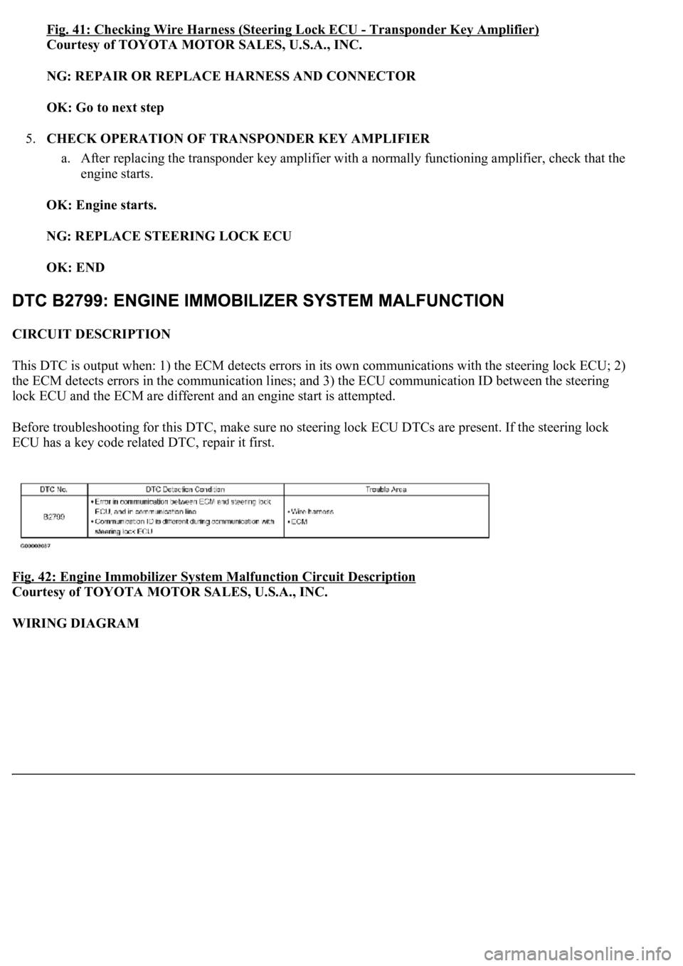
CIRCUIT DESCRIPTION
This DTC is output when: 1) the ECM detects errors in its own communications with the steering lock ECU; 2)
the ECM detects errors in the communication lines; and 3) the ECU communication ID between the steering
lock ECU and the ECM are different and an engine start is attempted.
Before troubleshooting for this DTC, make sure no steering lock ECU DTCs are present. If the steering lock
ECU has a key code related DTC, repair it first.
Fig. 42: Engine Immobilizer System Malfunction Circuit Description
Courtesy of TOYOTA MOTOR SALES, U.S.A., INC.
WIRING DIAGRAM
Page 3219 of 4500
Fig. 43: Engine Immobilizer System Malfunction - Wiring Diagram
Courtesy of TOYOTA MOTOR SALES, U.S.A., INC.
INSPECTION PROCEDURE
1.CHECK WIRE HARNESS (STEERING LOCK ECU - ECM)
a. Disconnect the S46 ECU connector.
b. Disconnect the E2 ECM connector
c. Measure the resistance of the wire harness side connectors.
Standard:
STEERING LOCK ECU - ECM - RESISTANCE TABLE
Tester connectionSpecified condition
S46-13 (EFIO) - E2-6 (IMI)Below 1 ohms
S46-4 (EFII) - E2-7 (IMO)Below 1 ohms
S46-13 (EFIO) or E2-6 (IMI) - Body ground10 kohms or higher
S46-4 (EFII) or E2-7 (IMO) - Body ground10 kohms or higher
Page 3221 of 4500
Fig. 44: Checking Wire Harness (Steering Lock ECU -ECM)
Courtesy of TOYOTA MOTOR SALES, U.S.A., INC.
NG: REPAIR OR REPLACE HARNESS AND CONNECTOR
OK: REPLACE ECM
CIRCUIT DESCRIPTION
This circuit provides power to operate the steering lock ECU.
WIRING DIAGRAM
Fig. 45: ECU Power Source Circuit
- Wiring Diagram