Page 2978 of 4500
1.DISCONNECT BATTERY NEGATIVE TERMINAL
2.REMOVE ENGINE ROOM SIDE COVER
a. Remove the 3 clips and engine room side cover.
3.REMOVE ECM COVER
a. Remove the 3 bolts and ECM cover.
4.REMOVE ECM
a. Remove the 2 nuts.
b. Disconnect the connector and remove the ECM.
5.REMOVE ECM GASKET
Page 2979 of 4500
Fig. 34: Removing ECM Gasket
Courtesy of TOYOTA MOTOR SALES, U.S.A., INC.
a. Peel off the sponge part of the gasket.
b.Spray gasket remover or equivalent on the remaining tape of the gasket.
Page 2981 of 4500
Fig. 36: Removing Taping Gasket Using Cutter
Courtesy of TOYOTA MOTOR SALES, U.S.A., INC.
6.INSTALL ECM GASKET
a. Clean the ECM's seal surface to the gasket with non-reside solvent.
b. Attach the gasket on the ECM.
7.INSTALL ECM
a. Connect the connector and install the ECM with the 2 nuts.
Page 2982 of 4500
Torque: 5.5 N.m (55 kgf.cm, 48 in..lbf)
8.INSTALL ECM COVER
a. Install the ECM cover with the 3 bolts.
Torque: 5.0 N.m (51 kgf.cm, 44 in..lbf)
9.INSTALL ENGINE ROOM SIDE COVER
a. Install the engine room side cover with the 3 clips.
10.CONNECT BATTERY NEGATIVE TERMINAL
11.CONFIGURE ECM FOR OPTIONAL DYNAMIC RADAR/LASER CRUISE CONTROL
a. Be sure to perform the following procedures after replacing the ECM.
1. Turn the ignition switch ON.
2. Turn the cruise main switch ON.
3. With the brake pedal depressed, set the cruise control main switch to RES/ACC 3 times within 3
seconds. Check that the VSC buzzer sounds at this time.
4. Turn the ignition switch OFF.
5. Connect the intelligent tester II to the DLC3.
6. Turn the ignition switch ON and push the intelligent tester II main switch ON.
7. Select the item "L/C Option Flag" in the Data List.
8. Check that YES is displayed.
12.POWER WINDOW CONTROL SYSTEM INITIALIZE (See INITIALIZATION
)
13.FRONT POWER SEAT CONTROL SYSTEM INITIALIZE (See INITIALIZATION
)
REPLACEMENT
1.REMOVE ACCELERATOR PEDAL ROD ASSY
Page 3166 of 4500
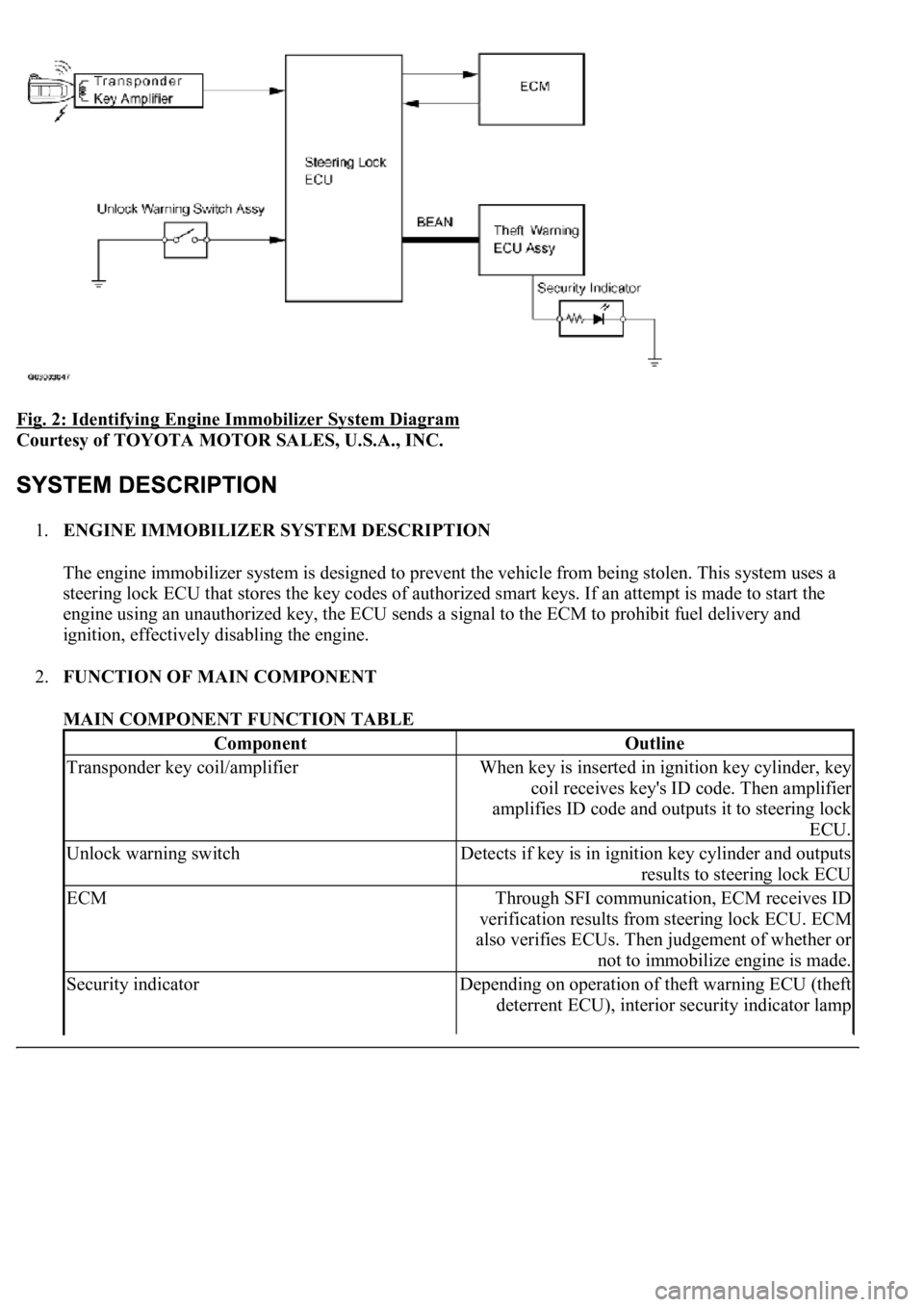
Fig. 2: Identifying Engine Immobilizer System Diagram
Courtesy of TOYOTA MOTOR SALES, U.S.A., INC.
1.ENGINE IMMOBILIZER SYSTEM DESCRIPTION
The engine immobilizer system is designed to prevent the vehicle from being stolen. This system uses a
steering lock ECU that stores the key codes of authorized smart keys. If an attempt is made to start the
engine using an unauthorized key, the ECU sends a signal to the ECM to prohibit fuel delivery and
ignition, effectively disabling the engine.
2.FUNCTION OF MAIN COMPONENT
MAIN COMPONENT FUNCTION TABLE
ComponentOutline
Transponder key coil/amplifierWhen key is inserted in ignition key cylinder, key
coil receives key's ID code. Then amplifier
amplifies ID code and outputs it to steering lock
ECU.
Unlock warning switchDetects if key is in ignition key cylinder and outputs
results to steering lock ECU
ECMThrough SFI communication, ECM receives ID
verification results from steering lock ECU. ECM
also verifies ECUs. Then judgement of whether or
not to immobilize engine is made.
Security indicatorDepending on operation of theft warning ECU (theft
deterrent ECU), interior security indicator lamp
Page 3167 of 4500
3.SYSTEM FUNCTION
When the steering lock ECU detects that the unlock warning switch is ON, the ECU provides current to
the transponder key coil and produces a faint electric wave. A transponder chip in the key and receives
the faint electric wave. Upon receiving the faint electric wave, the transponder chip outputs a key ID code
signal. The transponder key coil receives this signal, the transponder key amplifier amplifies it, and then
the signal is transmitted to the ECU.
The ECU matches the key's ID code with the vehicle's ID code, which was previously registered in the
ECU and then communicates the results to the ECM using SFI communication.
After the identification results show that the key's ID code matches the vehicle's ID code and the ECU has
confirmed their match: 1) the immobilizer system does not immobilize the engine and the engine starting
controls (fuel injection control and ignition control) enter standby mode; and 2) the ECU transmits a
security indicator signal that communicates "indicator off" to the theft warning ECU (theft deterrent
ECU). Then, the theft warning ECU turns off the security indicator lamp.
HINT:
Use this procedure to troubleshoot the engine immobilizer system.
The hand-held tester should be used in steps 4, 5 and 7.
1.VEHICLE BROUGHT TO WORKSHOP
2.CUSTOMER PROBLEM ANALYSIS CHECK AND SYMPTOM CHECK (See CUSTOMER
PROBLEM ANALYSIS CHECK )
3.CRANK ENGINE FOR MORE THAN 10 SECONDS
4.CHECK FOR DTCS
a. Check for DTCs and note any codes that are output.
b. Delete the DTC.
c. Recheck for DTCs. Based on the DTC output in (a), try to force output of the same SFI system
DTC or engine immobilizer system DTC by simulating the operation indicated by the DTC.
1. If the DTC does not reoccur, proceed to A.
2. If the SFI system DTC reoccurs, proceed to B.
3. If the engine immobilizer system DTC reoccurs, proceed to C.
B: Go to SFI SYSTEM (See HOW TO PROCEED WITH TROUBLESHOOTING
)
C: Go to step 8
illuminates or starts blinking.
Page 3170 of 4500
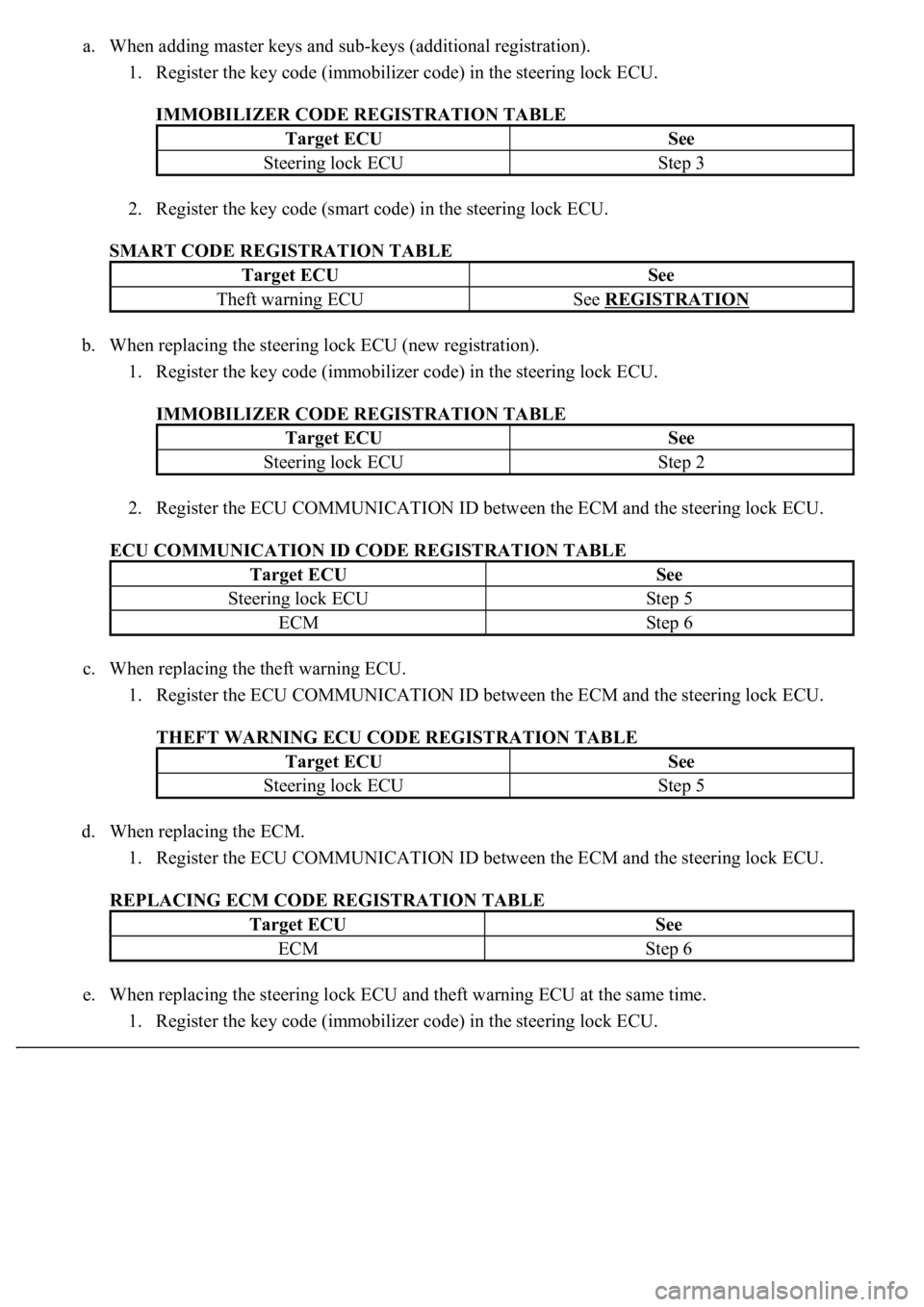
a. When adding master keys and sub-keys (additional registration).
1. Register the key code (immobilizer code) in the steering lock ECU.
IMMOBILIZER CODE REGISTRATION TABLE
2. Register the key code (smart code) in the steering lock ECU.
SMART CODE REGISTRATION TABLE
b. When replacing the steering lock ECU (new registration).
1. Register the key code (immobilizer code) in the steering lock ECU.
IMMOBILIZER CODE REGISTRATION TABLE
2. Register the ECU COMMUNICATION ID between the ECM and the steering lock ECU.
ECU COMMUNICATION ID CODE REGISTRATION TABLE
c. When replacing the theft warning ECU.
1. Register the ECU COMMUNICATION ID between the ECM and the steering lock ECU.
THEFT WARNING ECU CODE REGISTRATION TABLE
d. When replacing the ECM.
1. Register the ECU COMMUNICATION ID between the ECM and the steering lock ECU.
REPLACING ECM CODE REGISTRATION TABLE
e. When replacing the steering lock ECU and theft warning ECU at the same time.
1. Register the key code (immobilizer code) in the steering lock ECU.
Target ECUSee
Steering lock ECUStep 3
Target ECUSee
Theft warning ECUSee REGISTRATION
Target ECUSee
Steering lock ECUStep 2
Target ECUSee
Steering lock ECUStep 5
ECMStep 6
Target ECUSee
Steering lock ECUStep 5
Target ECUSee
ECMStep 6
Page 3171 of 4500
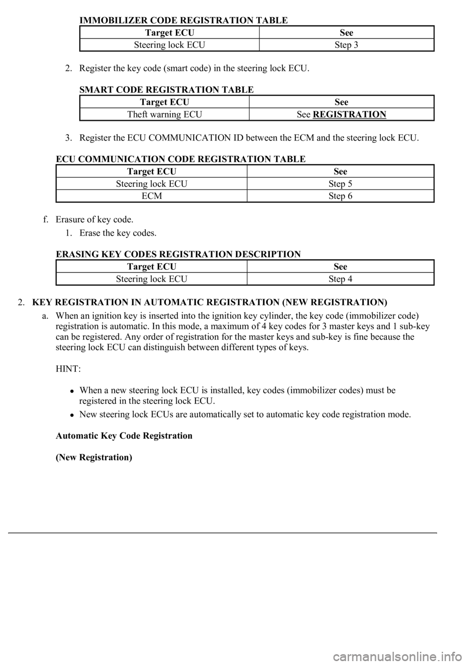
IMMOBILIZER CODE REGISTRATION TABLE
2. Register the key code (smart code) in the steering lock ECU.
SMART CODE REGISTRATION TABLE
3. Register the ECU COMMUNICATION ID between the ECM and the steering lock ECU.
ECU COMMUNICATION CODE REGISTRATION TABLE
f. Erasure of key code.
1. Erase the key codes.
ERASING KEY CODES REGISTRATION DESCRIPTION
2.KEY REGISTRATION IN AUTOMATIC REGISTRATION (NEW REGISTRATION)
a. When an ignition key is inserted into the ignition key cylinder, the key code (immobilizer code)
registration is automatic. In this mode, a maximum of 4 key codes for 3 master keys and 1 sub-key
can be registered. Any order of registration for the master keys and sub-key is fine because the
steering lock ECU can distinguish between different types of keys.
HINT:
When a new steering lock ECU is installed, key codes (immobilizer codes) must be
registered in the steering lock ECU.
New steering lock ECUs are automatically set to automatic key code registration mode.
Automatic Key Code Registration
(New Registration)
Target ECUSee
Steering lock ECUStep 3
Target ECUSee
Theft warning ECUSee REGISTRATION
Target ECUSee
Steering lock ECUStep 5
ECMStep 6
Target ECUSee
Steering lock ECUStep 4