Page 2893 of 4500
e. Measure the resistance according to the value(s) in the table below when the shift lever is moved to
each position.
Fig. 197: Disconnecting ECM Connector
Courtesy of TOYOTA MOTOR SALES, U.S.A., INC.
Standard:
Page 2894 of 4500
Fig. 198: Transmission Control Switch Reference Chart
Courtesy of TOYOTA MOTOR SALES, U.S.A., INC.
NG: REPAIR OR REPLACE HARNESS OR CONNECTOR (See ELECTRONIC CIRCUIT
INSPECTION PROCEDURE )
OK: PROCEED TO NEXT CIRCUIT INSPECTION SHOWN IN PROBLEM SYMPTOMS
TABLE
PATTERN SELECT SWITCH CIRCUIT (PWR)
CIRCUIT DESCRIPTION
Passenger side J/B ECU receives pattern select switch information, and sends it through the multiplex
communication system and CAN system to the ECM.
The ECM memory contains the shift programs for the NORMAL, POWER and SNOW patterns, 2 position, L
position and the loc
k-up patterns. By following the programs corresponding to the signals from the pattern
select switch, the neutral start and other various sensors, the ECM switches the solenoid valves ON and OFF,
and controls the transmission gear change and the lock-up clutch operation.
WIRING DIAGRAM
Page 2899 of 4500
Fig. 204: Identifying Passenger Side Junction Block Assy
Courtesy of TOYOTA MOTOR SALES, U.S.A., INC.
NG: REPAIR OR REPLACE HARNESS OR CONNECTOR (See ELECTRONIC CIRCUIT
INSPECTION PROCEDURE )
OK: PROCEED TO NEXT CIRCUIT INSPECTION SHOWN IN PROBLEM SYMPTOMS
TABLE
PATTERN SELECT SWITCH CIRCUIT (SNOW)
CIRCUIT DESCRIPTION
Passenger side J/B ECU receives pattern select switch information, and sends it through the multiplex
communication system and CAN system to the ECM.
ECT SNOW is the system that operates the throttle motor to control engine output to reduce skidding of the
driving wheels, guarantee takeoff acceleration, driving straightness and turning stability.
WIRING DIAGRAM
Page 2911 of 4500
Fig. 5: System Diagram Emission Control System (4 Of 4)
Courtesy of TOYOTA MOTOR SALES, U.S.A., INC.
ON-VEHICLE INSPECTION
1.INSPECT A/F COMPENSATION SYSTEM
a. Connect the hand-held tester to terminals E6-30 (OX1A) and E6-25 (O1A-) of the ECM.
b. Connect the hand-held tester to terminals E5-28 (OX2A) and E5-21 (02A-) of the ECM.
Page 2942 of 4500
SYSTEM DIAGRAM
Engine control system is determined by the ECM based on signals from various sensors.
Fig. 2: Engine Control
- System Diagram
Courtesy of TOYOTA MOTOR SALES, U.S.A., INC.
Page 2943 of 4500
ON-VEHICLE INSPECTION
1.INSPECTION THROTTLE BODY
a. Inspect the throttle control motor for operating sound.
1. Turn the ignition switch ON.
2. When turning the accelerator pedal position sensor lever, check the running sound of the
motor. The motor should be running smoothly without friction sounds.
If operation is not as specified, check the throttle control motor, wiring and ECM (see DTC P2118:
THROTTLE ACTUATOR CONTROL MOTOR CURRENT RANGE/PERFORMANCE ).
Fig. 3: Identifying Throttle Body
Courtesy of TOYOTA MOTOR SALES, U.S.A., INC.
b. Inspect the throttle position sensor.
Page 2944 of 4500

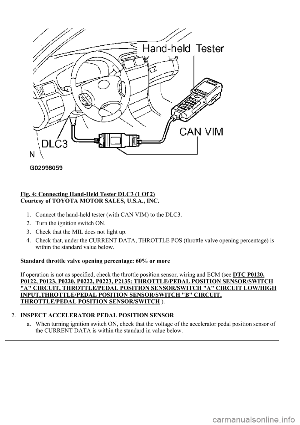
Fig. 4: Connecting Hand-Held Tester DLC3 (1 Of 2)
Courtesy of TOYOTA MOTOR SALES, U.S.A., INC.
1. Connect the hand-held tester (with CAN VIM) to the DLC3.
2. Turn the ignition switch ON.
3. Check that the MIL does not light up.
4. Check that, under the CURRENT DATA, THROTTLE POS (throttle valve opening percentage) is
within the standard value below.
Standard throttle valve opening percentage: 60% or more
If operation is not as specified, check the throttle position sensor, wiring and ECM (see DTC P0120,
P0122, P0123, P0220, P0222, P0223, P2135: THROTTLE/PEDAL POSITION SENSOR/SWITCH
"A" CIRCUIT, THROTTLE/PEDAL POSITION SENSOR/SWITCH "A" CIRCUIT LOW/HIGH
INPUT,THROTTLE/PEDAL POSITION SENSOR/SWITCH "B" CIRCUIT,
THROTTLE/PEDAL POSITION SENSOR/SWITCH ).
2.INSPECT ACCELERATOR PEDAL POSITION SENSOR
a. When turning ignition switch ON, check that the voltage of the accelerator pedal position sensor of
<0057004b004800030026003800350035002800310037000300270024003700240003004c00560003005a004c0057004b004c005100030057004b00480003005600570044005100470044005500470003004c0051000300590044004f005800480003004500
48004f0052005a00110003[
Page 2977 of 4500
Fig. 33: Identifying ECM Components
Courtesy of TOYOTA MOTOR SALES, U.S.A., INC.
REPLACEMENT