Page 3273 of 4500

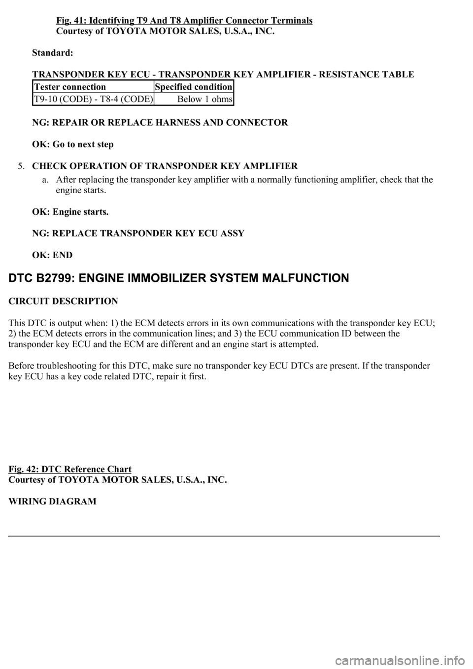
Fig. 41: Identifying T9 And T8 Amplifier Connector Terminals
Courtesy of TOYOTA MOTOR SALES, U.S.A., INC.
Standard:
TRANSPONDER KEY ECU - TRANSPONDER KEY AMPLIFIER - RESISTANCE TABLE
NG: REPAIR OR REPLACE HARNESS AND CONNECTOR
OK: Go to next step
5.CHECK OPERATION OF TRANSPONDER KEY AMPLIFIER
a. After replacing the transponder key amplifier with a normally functioning amplifier, check that the
engine starts.
OK: Engine starts.
NG: REPLACE TRANSPONDER KEY ECU ASSY
OK: END
CIRCUIT DESCRIPTION
This DTC is output when: 1) the ECM detects errors in its own communications with the transponder key ECU;
2) the ECM detects errors in the communication lines; and 3) the ECU communication ID between the
transponder key ECU and the ECM are different and an engine start is attempted.
Before troubleshooting for this DTC, make sure no transponder key ECU DTCs are present. If the transponder
key ECU has a key code related DTC, repair it first.
Fig. 42: DTC Reference Chart
Courtesy of TOYOTA MOTOR SALES, U.S.A., INC.
WIRING DIAGRAM
Tester connectionSpecified condition
T9-10 (CODE) - T8-4 (CODE)Below 1 ohms
Page 3274 of 4500
Fig. 43: DTC B2799 - Wiring Diagram
Courtesy of TOYOTA MOTOR SALES, U.S.A., INC.
INSPECTION PROCEDURE
1.CHECK WIRE HARNESS (TRANSPONDER KEY ECU ASSY - ECM)
a. Disconnect the T9 ECU connector.
b. Disconnect the E2 ECM connector.
c. Measure the resistance of the wire harness side connectors.
Page 3276 of 4500
Fig. 44: Identifying T9 ECU And E2 ECM Connector Terminals
Courtesy of TOYOTA MOTOR SALES, U.S.A., INC.
Standard:
TRANSPONDER KEY ECU ASSY - ECM - RESISTANCE TABLE
NG: REPAIR OR REPLACE HARNESS AND CONNECTOR
OK: REPLACE ECM
CIRCUIT DESCRIPTION
This circuit provides power to operate the transponder key ECU.
WIRING DIAGRAM
Tester connectionSpecified condition
T9-6 (EFIO) - E2-6 (IMI)Below 1 ohms
T9-7 (EFII) - E2-7 (IMO)Below 1 ohms
T9-6 (EFIO) or E2-6 (IMI) -Body ground10 kohms or higher
T9-7 (EFII) or E2-7 (IMO) -Body ground10 kohms or higher
Page 3313 of 4500

13.DRAIN AUTOMATIC TRANSMISSION FLUID
14.REMOVE RADIATOR ASSY (See REPLACEMENT
)
15.DISCONNECT FUEL PIPE SUB-ASSY NO.2 (See REPLACEMENT
)
16.REMOVE FAN AND GENERATOR V BELT (See REPLACEMENT
)
17.DISCONNECT ENGINE WIRE
a. Disconnect the engine wire from the ECM box.
b. Remove the nut, and disconnect the generator wire from the generator.
c. Disconnect the wire for generator wire from the wire clamp on generator.
d. Remove the bolt, and disconnect the ground cable from the stay on the generator.
e. Remove the 2 bolts, and disconnect the PS oil hose from the No. 1 oil pan.
f. Remove the bolt, and disconnect the ground strap from the body.
18.DISCONNECT AIR HOSE NO.5
19.DISCONNECT FUEL VAPOR FEED HOSE NO.2
20.DISCONNECT HEATER WATER INLET HOSE A
21.DISCONNECT HEATER WATER OUTLET HOSE A (FROM HEATER UNIT)
22.DISCONNECT VANE PUMP OIL RESERVOIR ASSY
23.DISCONNECT VANE PUMP ASSY
a. Disconnect the 2 PS air hoses.
b. Remove the 2 screws and RH engine under cover.
c. Disconnect the PS oil pressure switch connector.
d. Remove the 2 bolts and nut, and disconnect the pump from the engine.
e. Support the pump securely.
24.DISCONNECT COOLER COMPRESSOR ASSY
a. Disconnect the compressor connector.
b. Disconnect the wire clamp from the wire bracket on the compressor.
c. Remove the bolt, nut and stay.
d. Remove the bolt, and disconnect the wire bracket from the compressor.
e. Remove the bolt, and disconnect the compressor from the engine.
f. Support the cooler compressor securely.
25.REMOVE FRONT FLOOR BRACE CENTER
a. Remove the 4 bolts and brace center.
26.REMOVE EXHAUST PIPE ASSY (See REPLACEMENT
)
27.REMOVE W/ CATALYST CONVERTER ASSY
28.REMOVE FRONT FLOOR HEAT INSULATOR NO.1
29.REMOVE PARKING BRAKE CABLE HEAT INSULATOR
30.REMOVE PROPELLER W/ CENTER BEARING SHAFT ASSY (See OVERHAUL
)
31.REMOVE FLOOR SHIFT GEAR SHIFTING ROD SUB-ASSY
32.REMOVE STEERING SLIDING W/ SHAFT YOKE SUB-ASSY
Page 3360 of 4500
Fig. 80: Installing Vane Pump Assy
Courtesy of TOYOTA MOTOR SALES, U.S.A., INC.
131.INSTALL VANE PUMP OIL RESERVOIR ASSY
132.CONNECT HEATER WATER OUTLET HOSE A (FROM HEATER UNIT)
133.CONNECT HEATER WATER INLET HOSE A
134.CONNECT FUEL VAPOR FEED HOSE NO.2
135.CONNECT AIR HOSE NO.5
136.CONNECT ENGINE WIRE
a. Connect the engine wire from the ECM box.
b. Install the nut, and connect the generator wire to the generator.
c. Connect the wire for generator wire to the wire clamp on generator.
d. Connect the ground cable to the stay on generator with the bolt.
e. Connect the PS oil hose to the No. 1 oil pan with the 2 bolts.
f. Connect the ground strap to the body with the 2 bolts.
137.INSTALL FAN AND GENERATOR V BELT (See REPLACEMENT
)
138.CONNECT FUEL PIPE SUB-ASSY NO.2 (See REPLACEMENT
)
139.INSTALL RADIATOR ASSY (See REPLACEMENT
)
Page 4100 of 4500
Fig. 2: Fuel System - System Diagram (1 Of 3)
Courtesy of TOYOTA MOTOR SALES, U.S.A., INC.
Fuel s
ystem is determined by the ECM based on signals from various sensors.
Page 4113 of 4500
Fig. 15: Connecting Hand-Held Tester DLC3
Courtesy of TOYOTA MOTOR SALES, U.S.A., INC.
c. Select the ACTIVE TEST mode on the hand-held tester.
d. Please refer to the hand-held tester operator's manual for further details.
e. Check that there is pressure in the fuel inlet hose from the fuel filter.
HINT:
If there is fuel pressure, you will hear the sound of fuel flowing. If there is no pressure, check the
fusible link, fuses, EFI MAIN relay, fuel pump, ECM and wiring connections.
f. Turn the ignition switch to LOCK.
g. Disconnect the hand-held tester from the DLC3.
2.CHECK FUEL PRESSURE
a. Check that the battery positive voltage is above 12 V.
b. Disconnect the negative (-) terminal cable from the battery.
c. Remove the fuel pressure pulsation damper from the RH delivery pipe (see REPLACEMENT
).
d. Install the fuel pipe sub-ass
y No. 2 and SST (pressure gauge) to the delivery pipe with the 3 lower
Page 4327 of 4500
LOCATION
Fig. 1: Identifying Ignition System Components And Replacement Location
Courtesy of TOYOTA MOTOR SALES, U.S.A., INC.
SYSTEM DIAGRAM
The ECM determines ignition timing based on signals from various sensors.