Page 1605 of 4500
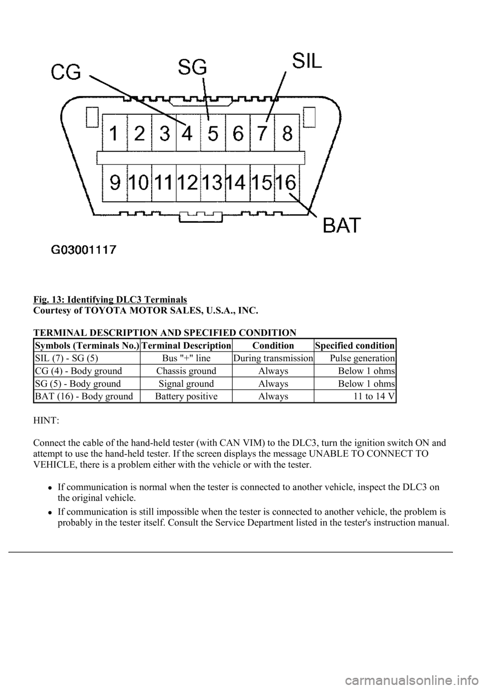
Fig. 13: Identifying DLC3 Terminals
Courtesy of TOYOTA MOTOR SALES, U.S.A., INC.
TERMINAL DESCRIPTION AND SPECIFIED CONDITION
HINT:
Connect the cable of the hand-held tester (with CAN VIM) to the DLC3, turn the ignition switch ON and
attempt to use the hand-held tester. If the screen displays the message UNABLE TO CONNECT TO
VEHICLE, there is a problem either with the vehicle or with the tester.
If communication is normal when the tester is connected to another vehicle, inspect the DLC3 on
the original vehicle.
If communication is still impossible when the tester is connected to another vehicle, the problem is
probably in the tester itself. Consult the Service Department listed in the tester's instruction manual.
Symbols (Terminals No.)Terminal DescriptionConditionSpecified condition
SIL (7) - SG (5)Bus "+" lineDuring transmissionPulse generation
CG (4) - Body groundChassis groundAlwaysBelow 1 ohms
SG (5) - Body groundSignal groundAlwaysBelow 1 ohms
BAT (16) - Body groundBattery positiveAlways11 to 14 V
Page 1624 of 4500
Fig. 26: Identifying Seat Climate Control Blower Connector Terminals And Seat Climate
Controller Connector Terminals
Courtesy of TOYOTA MOTOR SALES, U.S.A., INC.
NG: REPAIR OR REPLACE HARNESS AND CONNECTOR
OK: Go to next step
9.CHECK SEAT HEATER (SEATBACK) (SEE INSPECTION
)
NG: REPLACE REAR SEATBACK PAD
OK: Go to next step
10.INSPECT SEAT HEATER (SEAT CUSHION) (SEE INSPECTION
)
NG: REPLACE SEAT CUSHION PAD
OK: Go to next step
11.CHECK WIRE HARNESS (SEAT CLIMATE CONTROL BLOWER (CLIMATE CONTROL
ECU) - SEAT HEATER)
HINT:
When the indicator of rear left side is blinking, check the rear left side connector. When the indicator of
rear right side is blinking, check the rear right side connector.
a. Disconnect the C28 or C30 blower connector.
b. Disconnect the S60 or S61 heater connector.
c. Measure the resistance of the wire harness side connectors.
Standard:
Rear LH
TESTER CONNECTION AND SPECIFIED CONDITION - REAR LH
Rear RH
TESTER CONNECTION AND SPECIFIED CONDITION - REAR RH
Tester ConnectionSpecified Condition
C28-8 (E) - S60-3 (E)Below 1 ohms
C28-8 (E) - S60-1 (B)10 kohms or higher
C28-18 (B) - S60-1 (B)Below 1 ohms
C28-18 (B) - S60-3 (E)10 kohms or higher
Page 1627 of 4500
Fig. 27: Identifying Seat Climate Control Blower Connector Terminals And Seat Heater Connector
Terminals
Courtesy of TOYOTA MOTOR SALES, U.S.A., INC.
NG: REPAIR OR REPLACE HARNESS AND CONNECTOR
OK: Go to next step
12.INSPECT SEAT CLIMATE CONTROL BLOWER (FAN MOTOR OF SEATBACK) (SEE
INSPECTION
)
NG: REPLACE SEAT CLIMATE CONTROL BLOWER (SEATBACK)
OK: Go to next step
13.CHECK WIRE HARNESS (SEAT CLIMATE CONTROL BLOWER (CLIMATE CONTROL
ECU) - SEAT CLIMATE FAN MOTOR)
HINT:
When the indicator of rear left side is blinking, check the rear left side connector. When the indicator of
rear right side is blinking, check the rear right side connector.
a. Disconnect the C27 or C29 blower connector.
b. Disconnect the S56 or S58 motor connector.
c. Measure the resistance of the wire harness side connectors.
Standard:
Rear LH
TESTER CONNECTION AND SPECIFIED CONDITION - REAR LH
Rear RH
TESTER CONNECTION AND SPECIFIED CONDITION - REAR RH
Tester ConnectionSpecified Condition
C27-3 (BBS) - S56-3 (BBS)Below 1 ohms
C27-3 (BBS) - S56-2 (BFB(+))10 kohms or higher
C27-2 (BFB+) - S56-2 (BFB(+))Below 1 ohms
C27-2 (BFB+) - S56-3 (BBS)10 kohms or higher
Tester ConnectionSpecified Condition
C29-3 (BBS) - S58-3 (BBS)Below 1 ohms
C29-3 (BBS) - S58-2 (BFB(+))10 kohms or higher
C29-2 (BFB+) - S58-2 (BFB(+))Below 1 ohms
Page 1639 of 4500
TESTER CONNECTION AND SPECIFIED CONDITION - DRIVER SIDE
Passenger side
TESTER CONNECTION AND SPECIFIED CONDITION - PASSENGER SIDE
Fig. 35: Identifying Seat Climate Control Blower Connector Terminals
Courtesy of TOYOTA MOTOR SALES, U.S.A., INC.
NG: REPLACE SEAT CLIMATE CONTROL CONTROLLER (CLIMATE CONTROL ECU)
OK: Go to next step
5.INSPECT SEAT CLIMATE CONTROL CONTROLLER (THERMISTOR OF SEATBACK)
Tester ConnectionConditionSpecified Condition
C20-13 (V5) - Body GroundIgnition switch ON5 V
Tester ConnectionConditionSpecified Condition
C21-13 (V5) - Body GroundIgnition switch ON5 V
Page 1645 of 4500
Fig. 38: Identifying Seat Climate Control Blower Connector Terminals
Courtesy of TOYOTA MOTOR SALES, U.S.A., INC.
NG: REPAIR OR REPLACE HARNESS AND CONNECTOR
OK: Go to next step
10.CHECK WIRE HARNESS (SEAT CLIMATE CONTROL BLOWER (CLIMATE CONTROL
ECU) - BODY GROUND)
HINT:
When the rear LH indicator is blinking, check the rear LH side connector. When the rear RH indicator is
blinking, check the rear right RH side connector.
a. Measure the voltage of the wire harness side connector.
Standard:
Rear LH
TESTER CONNECTION AND SPECIFIED CONDITION - REAR LH
Rear RH
TESTER CONNECTION AND SPECIFIED CONDITION - REAR RH
Tester ConnectionConditionSpecified Condition
C27-18 (V5) - Body groundIgnition switch ON, Climate control switch ON5 V
Tester ConnectionConditionSpecified Condition
C29-18 (V5) - Body groundIgnition switch ON, Climate control switch ON5 V
Page 1651 of 4500
Fig. 41: Identifying Seat Climate Control Blower Connector Terminals And Seat Climate
Controller Connector Terminals
Courtesy of TOYOTA MOTOR SALES, U.S.A., INC.
NG: REPAIR OR REPLACE HARNESS AND CONNECTOR
OK: Go to next step
15.INSPECT SEAT HEATER (THERMISTOR)
HINT:
When the rear LH indicator is blinking, check the rear LH side connector. When the rear RH indicator is
blinking, check the rear right RH side connector.
a. Disconnect the S60 or S61 heater connector.
b. Check the resistance between the terminals of the heater.
Standard:
Rear LH
TESTER CONNECTION AND SPECIFIED CONDITION - REAR LH
Rear RH
TESTER CONNECTION AND SPECIFIED CONDITION - REAR RH
Tester ConnectionAmbient TemperatureSpecified Condition
S60-2 (H5) - S60-4 (HS)10°C (50°F)Approx. 3.7 kohms
S60-2 (H5) - S60-4 (HS)25°C (77°F)Approx. 2 ohms
S60-2 (H5) - S60-4 (HS)30°C (86°F)Approx. 1.7 ohms
Tester ConnectionAmbient TemperatureSpecified Condition
S61-2 (H5) - S61-4 (HS)10°C (50°F)Approx. 3.7 kohms
S61-2 (H5) - S61-4 (HS)25°C (77°F)Approx. 2 ohms
S61-2 (H5) - S61-4 (HS)30°C (86°F)Approx. 1.7 ohms
Page 1660 of 4500
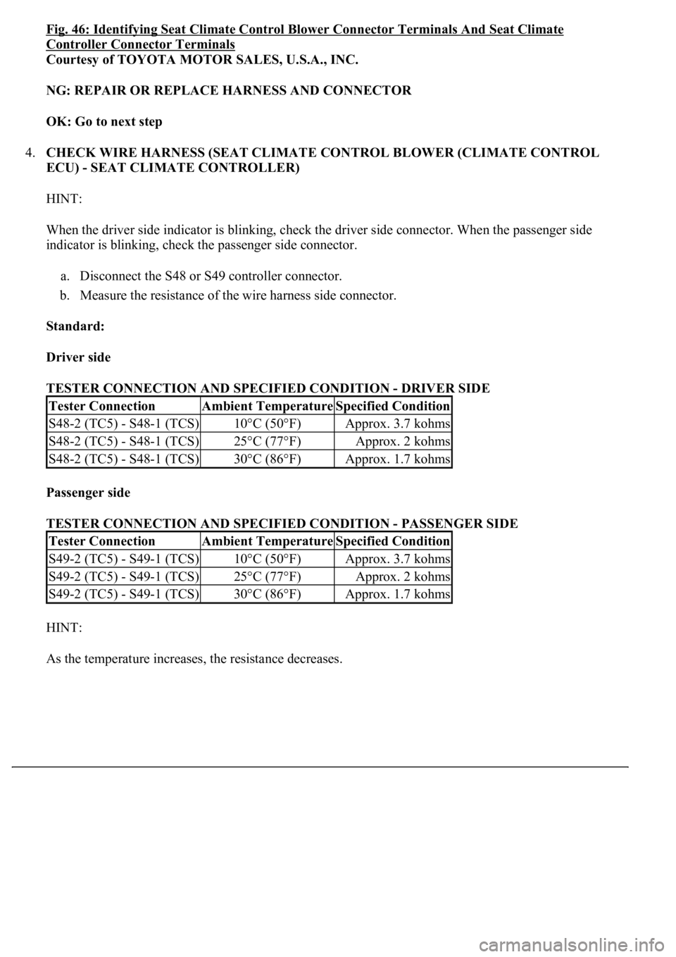
Fig. 46: Identifying Seat Climate Control Blower Connector Terminals And Seat Climate
Controller Connector Terminals
Courtesy of TOYOTA MOTOR SALES, U.S.A., INC.
NG: REPAIR OR REPLACE HARNESS AND CONNECTOR
OK: Go to next step
4.CHECK WIRE HARNESS (SEAT CLIMATE CONTROL BLOWER (CLIMATE CONTROL
ECU) - SEAT CLIMATE CONTROLLER)
HINT:
When the driver side indicator is blinking, check the driver side connector. When the passenger side
indicator is blinking, check the passenger side connector.
a. Disconnect the S48 or S49 controller connector.
b. Measure the resistance of the wire harness side connector.
Standard:
Driver side
TESTER CONNECTION AND SPECIFIED CONDITION - DRIVER SIDE
Passenger side
TESTER CONNECTION AND SPECIFIED CONDITION - PASSENGER SIDE
HINT:
As the temperature increases, the resistance decreases.
Tester ConnectionAmbient TemperatureSpecified Condition
S48-2 (TC5) - S48-1 (TCS)10°C (50°F)Approx. 3.7 kohms
S48-2 (TC5) - S48-1 (TCS)25°C (77°F)Approx. 2 kohms
S48-2 (TC5) - S48-1 (TCS)30°C (86°F)Approx. 1.7 kohms
Tester ConnectionAmbient TemperatureSpecified Condition
S49-2 (TC5) - S49-1 (TCS)10°C (50°F)Approx. 3.7 kohms
S49-2 (TC5) - S49-1 (TCS)25°C (77°F)Approx. 2 kohms
S49-2 (TC5) - S49-1 (TCS)30°C (86°F)Approx. 1.7 kohms
Page 1664 of 4500
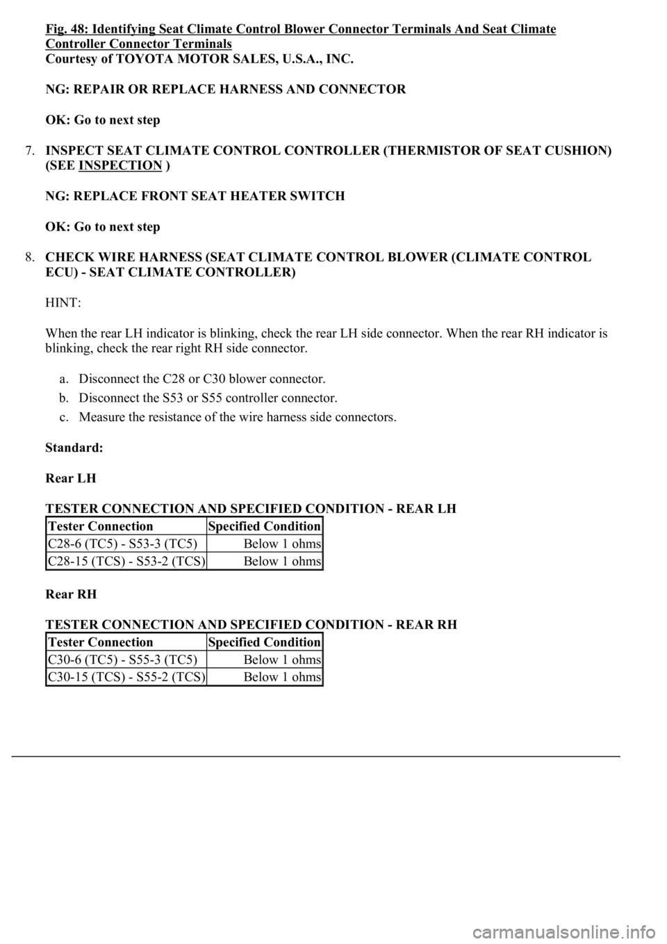
Fig. 48: Identifying Seat Climate Control Blower Connector Terminals And Seat Climate
Controller Connector Terminals
Courtesy of TOYOTA MOTOR SALES, U.S.A., INC.
NG: REPAIR OR REPLACE HARNESS AND CONNECTOR
OK: Go to next step
7.INSPECT SEAT CLIMATE CONTROL CONTROLLER (THERMISTOR OF SEAT CUSHION)
(SEE INSPECTION
)
NG: REPLACE FRONT SEAT HEATER SWITCH
OK: Go to next step
8.CHECK WIRE HARNESS (SEAT CLIMATE CONTROL BLOWER (CLIMATE CONTROL
ECU) - SEAT CLIMATE CONTROLLER)
HINT:
When the rear LH indicator is blinking, check the rear LH side connector. When the rear RH indicator is
blinking, check the rear right RH side connector.
a. Disconnect the C28 or C30 blower connector.
b. Disconnect the S53 or S55 controller connector.
c. Measure the resistance of the wire harness side connectors.
Standard:
Rear LH
TESTER CONNECTION AND SPECIFIED CONDITION - REAR LH
Rear RH
TESTER CONNECTION AND SPECIFIED CONDITION - REAR RH
Tester ConnectionSpecified Condition
C28-6 (TC5) - S53-3 (TC5)Below 1 ohms
C28-15 (TCS) - S53-2 (TCS)Below 1 ohms
Tester ConnectionSpecified Condition
C30-6 (TC5) - S55-3 (TC5)Below 1 ohms
C30-15 (TCS) - S55-2 (TCS)Below 1 ohms