Page 1510 of 4500
Fig. 6: Identifying Front Sonar Display
Courtesy of TOYOTA MOTOR SALES, U.S.A., INC.
g. Check the multi-information display and the buzzer sounding condition when the back sensor
detects an obstacle.
Operation condition:
Back sonar:
CLEARANCE SONAR MAIN SWITCH
Page 1512 of 4500
Fig. 7: Identifying Back Sonar Display
Courtesy of TOYOTA MOTOR SALES, U.S.A., INC.
h. Check the multi-information display, the multi-display and the buzzer sounding condition when the
clearance sonar sensor detects an obstacle.
Operation condition:
Front clearance sonar:
CLEARANCE SONAR MAIN SWITCH
Page 1515 of 4500
c. After turning the ignition switch to the ON position, wait for 2 seconds or more, then turn the
clearance sonar main switch on. Check the multi-information display and the buzzer sounding
condition.
Standard:
After the main switch is turned on, the multi-information display shows the Fig. 9
below
for approximatel
y 2 seconds and the buzzer sounds for approximately 1 second then the
detection mode begins.
Fig. 9: Identifying Multi
-Information Display
Courtesy of TOYOTA MOTOR SALES, U.S.A., INC.
HINT:
Multi-information display:
The malfunctioning sensor blinks on the display when the wire harness or the connector is
faulty and requires repair or replacement, or when trouble is detected in the ultrasonic sensor
circuits. After the sensor operation returns to normal, the detection mode will finish
normall
y.
Page 1520 of 4500
Fig. 13: Identifying Clearance Warning ECU Assy Terminals
Courtesy of TOYOTA MOTOR SALES, U.S.A., INC.
TERMINAL NUMBER SPECIFIED CONDITION
Terminal No.
(Symbols)Wiring
colorTerminal
descriptionConditionSpecified
value
C17-3 (CLSW) -
C17-7 (MGND)LG - W-BClearance sonar
main switchIG switch ON
Clearance sonar main switch ON
10 to 14 V
C17-4 (FBZ+) -
C17-7 (MGND)GR - W-BBuzzer No.1
outputBuzzer No.1 sounding (when the front
sonar and/or front clearance sonar senses
something)Pulse
generation
C17-5 (IG) - C17-
7 (MGND)BR - W-BIG signal/IG
power sourceIG switch ON10 to 14 V
C17-6 (RBZ+) -
C17-7 (MGND)L - W-BBuzzer No. 2
outputBuzzer No.2 sounding (when the back
sonar and/or rear clearance sonar senses
something)Pulse
generation
C17-7 (MGND) -
Body groundW-B -
Body
ground
ECU groundAlwaysBelow 1
ohms
Page 1522 of 4500

various data output from the vehicle's clearance warning ECU.
The clearance warning ECU records DTCs when the computer detects a malfunction in the
computer itself or in its circuits.
To check the DTCs, connect the hand-held tester to the DLC3 on the vehicle. The hand-held
tester enables you to erase the DTCs, activate the several actuators and check the freeze
frame data and data list.
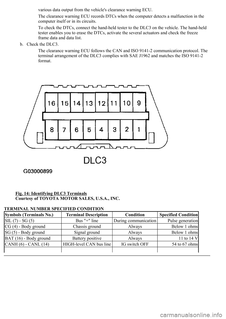
b. Check the DLC3.
The clearance warning ECU follows the CAN and ISO 9141-2 communication protocol. The
terminal arrangement of the DLC3 complies with SAE J1962 and matches the ISO 9141-2
format.
Fig. 14: Identifying DLC3 Terminals
Courtesy of TOYOTA MOTOR SALES, U.S.A., INC.
TERMINAL NUMBER SPECIFIED CONDITION
Symbols (Terminals No.)Terminal DescriptionConditionSpecified Condition
SIL (7) - SG (5)Bus "+" lineDuring communicationPulse generation
CG (4) - Body groundChassis groundAlwaysBelow 1 ohms
SG (5) - Body groundSignal groundAlwaysBelow 1 ohms
BAT (16) - Body groundBattery positiveAlways11 to 14 V
CANH (6) - CANL (14)HIGH-level CAN bus lineIG switch OFF54 to 67 ohms
Page 1530 of 4500
Fig. 21: Identifying Ultrasonic Sensor Number-1 Terminals
Courtesy of TOYOTA MOTOR SALES, U.S.A., INC.
OK: Go To Next Step.
2.CHECK HARNESS AND CONNECTOR (CLEARANCE WARNING ECU ASSY -
ULTRASONIC SENSOR NO. 1)
a. Disconnect the C17 connector from the clearance warning ECU assy.
b. Disconnect the U3 connector from ultrasonic sensor No.1.
c. Measure the resistance according to the value (s) in the table below.
TESTER CONNECTION SPECIFIED CONDITION
Tester connection (Symbols)ConditionSpecified value
C17-21 (FLS) - U3-2AlwaysBelow 1 ohms
C17-8 (FGND) - U3-1AlwaysBelow 1 ohms
Page 1533 of 4500
Fig. 22: Identifying Clearance Warning ECU Assy Terminals
Courtesy of TOYOTA MOTOR SALES, U.S.A., INC.
NG: REPAIR OR REPLACE HARNESS OR CONNECTOR
OK: REPLACE CLEARANCE WARNING ECU ASSY (SEE REPLACEMENT
)
CIRCUIT DESCRIPTION
Ultrasonic sensor consists of a sensor portion that transmits and receives ultrasonic waves and a pre-amplifier
that amplifies them. The ultrasonic sensor outputs the ultrasonic transmission and reception signals to the
clearance warning ECU assy.
Fig. 23: DTC B2232 Detection Condition And Trouble Area Description Chart
Courtesy of TOYOTA MOTOR SALES, U.S.A., INC.
WIRING DIAGRAM
Page 1534 of 4500
Fig. 24: Front Left Sensor Wiring Diagram
Courtesy of TOYOTA MOTOR SALES, U.S.A., INC.
INSPECTION PROCEDURE
1.INSPECT ULTRASONIC SENSOR NO.1
a. Remove ultrasonic sensor No.1.
b. Measure the resistance according to the value (s) in the table below.
TESTER CONNECTION SPECIFIED CONDITION
Fig. 25: Identifying Ultrasonic Sensor No.1 Terminals
Courtesy of TOYOTA MOTOR SALES, U.S.A., INC.
Tester connectionConditionSpecified condition
1-2Always10 +/- 2 kohms