Page 1572 of 4500
Standard:
TESTER CONNECTION SPECIFIED CONDITION
Fig. 61: Identifying C17 Connector Terminals (1 Of 2)
Courtesy of TOYOTA MOTOR SALES, U.S.A., INC.
NG: REPAIR OR REPLACE HARNESS OR CONNECTOR (CLEARANCE WARNING ECU
ASSY - BATTERY)
OK: Go To Next Step.
3.CHECK HARNESS AND CONNECTOR (CLEARANCE WARNING ECU ASSY - BODY
GROUND)
a. Disconnect the C17 connector from the clearance warning ECU assy.
b. Measure the resistance according to the value (s) in the table below.
Standard:
TESTER CONNECTION SPECIFIED CONDITION
Tester connection (Symbols)ConditionSpecified condition
C17-5 (IG)- Body groundIG switch ON10 to 14 V
Page 1573 of 4500
Fig. 62: Identifying C17 Connector Terminals (2 Of 2)
Courtesy of TOYOTA MOTOR SALES, U.S.A., INC.
NG: REPAIR OR REPLACE HARNESS OR CONNECTOR (CLEARANCE WARNING ECU
ASSY - BODY GROUND)
OK: PROCEED TO NEXT CIRCUIT INSPECTION SHOWN IN PROBLEM SYMPTOMS
TABLE
CIRCUIT DESCRIPTION
Turning this switch on activates the clearance sonar system.
WIRING DIAGRAM
Tester connection (Symbols)ConditionSpecified condition
C17-7 (MGND) - Body groundAlwaysBelow 1 ohms
Page 1576 of 4500
Fig. 65: Identifying CLSW Terminals
Courtesy of TOYOTA MOTOR SALES, U.S.A., INC.
OK: REPLACE CLEARANCE WARNING ECU ASSY (SEE REPLACEMENT
)
NG: Go To Next Step.
3.CHECK HARNESS AND CONNECTOR (CLEARANCE WARNING ECU ASSY - BODY
GROUND)
a. Disconnect the C17 connector from the clearance warning ECU assy.
b. Measure the resistance according to the value (s) in the table below.
Standard:
TESTER CONNECTION SPECIFIED CONDITION
Tester connectionConditionSpecified condition
C17-7 (MGND) - Body groundAlwaysBelow 1 ohms
Page 1577 of 4500
Fig. 66: Identifying C17 Connector Terminals
Courtesy of TOYOTA MOTOR SALES, U.S.A., INC.
NG: REPAIR OR REPLACE HARNESS OR CONNECTOR (CLEARANCE WARNING ECU
ASSY - BODY GROUND)
OK: Go To Next Step.
4.INSPECT OUTER MIRROR SWITCH ASSY
a. Disconnect the O5 connector from the clearance sonar main switch.
b. Measure the resistance according to the value (s) in the table below.
Standard:
TESTER CONNECTION SPECIFIED CONDITION
Tester connection (Symbols)ConditionSpecified condition
O5-3 - O5-4Clearance sonar main switch off10 kohms or higher
O5-3 - O5-4Clearance sonar main switch onBelow 1 ohms
Page 1595 of 4500
Fig. 8: Identifying Terminals Of Climate Control ECU - LH (FR)
Courtesy of TOYOTA MOTOR SALES, U.S.A., INC.
a. Disconnect the C20 and S48 blower connectors.
b. Measure the voltage and resistance of the wire harness side connectors.
Standard:
TERMINAL DESCRIPTION AND SPECIFIED CONDITION
Symbols
(Terminal
No.)Wiring
ColorTerminal
DescriptionConditionSpecified
Condition
E (C20 - 8) -
Body groundW-B -
Body
ground
GroundAlwaysBelow 1 ohms
IG (C20 -7) -
Body groundB - Body
groundPower sourceIgnition switch ON10 to 14 V
V5 (C20 - 13)
- VG (C20 - 9)GR-R - LPower supply for
volume switchAlways5 kohms
VS (C20 - 12)
- VG (20 - 9)R-B - LVolume switch signalTurn volume switch: Max0 ohms --> 5
kohms
TB5 (C20 - 4)
- TBS (20 - 3)L-Y -
BR-WSeatback temperature
sensorSeatback temperature: 10°C --
> 30°C (50°F --> 86°F)Approx. 3.7
kohms -->
Approx. 1.7
Page 1597 of 4500
2.CHECK SEAT CLIMATE CONTROL BLOWER RH (FR) (CLIMATE CONTROL ECU)
Fig. 9: Identifying Terminals Of Climate Control ECU
- RH (FR)
Courtesy of TOYOTA MOTOR SALES, U.S.A., INC.
a. Disconnect the C21 and S49 blower connectors.
b. Measure the voltage and resistance of the wire harness side connectors.
Standard:
TERMINAL DESCRIPTION AND SPECIFIED CONDITION
Symbols
(Terminal
No.)Wiring
ColorTerminal DescriptionConditionSpecified
Condition
E (C21-8) -
Body groundW-B -
Body
ground
GroundAlwaysBelow 1 ohms
IG (C21-7) -
Body groundG - Body
groundPower sourceIgnition switch ON10 to 14 V
V5 (C21-13) -
VG (C21-9)BR-Y -
V-RPower source for
volume switchAlways5 kohms
VS (C21-12) -
VG (21-9)B-O - V-
RVolume switch signalTurn volume switch: Max.
COOL --> Max. WARM0 ohms --> 5
kohms
TB5 (C21-4) - Seatback temperature Turn volume switch: 10°C -->
Approx. 3.7
kohms -->
Page 1599 of 4500

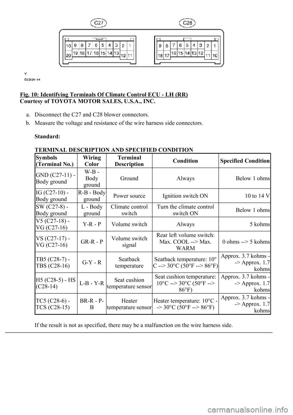
Fig. 10: Identifying Terminals Of Climate Control ECU - LH (RR)
Courtesy of TOYOTA MOTOR SALES, U.S.A., INC.
a. Disconnect the C27 and C28 blower connectors.
b. Measure the voltage and resistance of the wire harness side connectors.
Standard:
TERMINAL DESCRIPTION AND SPECIFIED CONDITION
If the result is not as specified, there ma
y be a malfunction on the wire harness side.
Symbols
(Terminal No.)Wiring
ColorTerminal
DescriptionConditionSpecified Condition
GND (C27-11) -
Body groundW-B -
Body
ground
GroundAlwaysBelow 1 ohms
IG (C27-10) -
Body groundR-B - Body
groundPower sourceIgnition switch ON10 to 14 V
SW (C27-8) -
Body groundL - Body
groundClimate control
switchTurn the climate control
switch ONBelow 1 ohms
V5 (C27-18) -
VG (C27-16)Y-R - PVolume switchAlways5 kohms
VS (C27-17) -
VG (C27-16)GR-R - PVolume switch
signalRear left volume switch:
Max. COOL --> Max.
WARM
0 ohms --> 5 kohms
TB5 (C28-7) -
TBS (C28-16)G-Y - RSeatback
temperatureSeatback temperature: 10°
C --> 30°C (50°F --> 86°F)Approx. 3.7 kohms -
-> Approx. 1.7
kohms
H5 (C28-5) - HS
(C28-14)L-B - Y-RSeat cushion
temperature sensorSeat cushion temperature:
10°C --> 30°C (50°F -->
86°F)Approx. 3.7 kohms -
-> Approx. 1.7
kohms
TC5 (C28-6) -
TCS (C28-15)BR-R - P-
BHeater
temperature sensorHeater temperature: 10°C -
-> 30°C (50°F --> 86°F)Approx. 3.7 kohms -
-> Approx. 1.7
kohms
Page 1601 of 4500

HINT:
*: For vehicles with a front seat climate control system
If the result is not as specified, the ECU may have a malfunction.
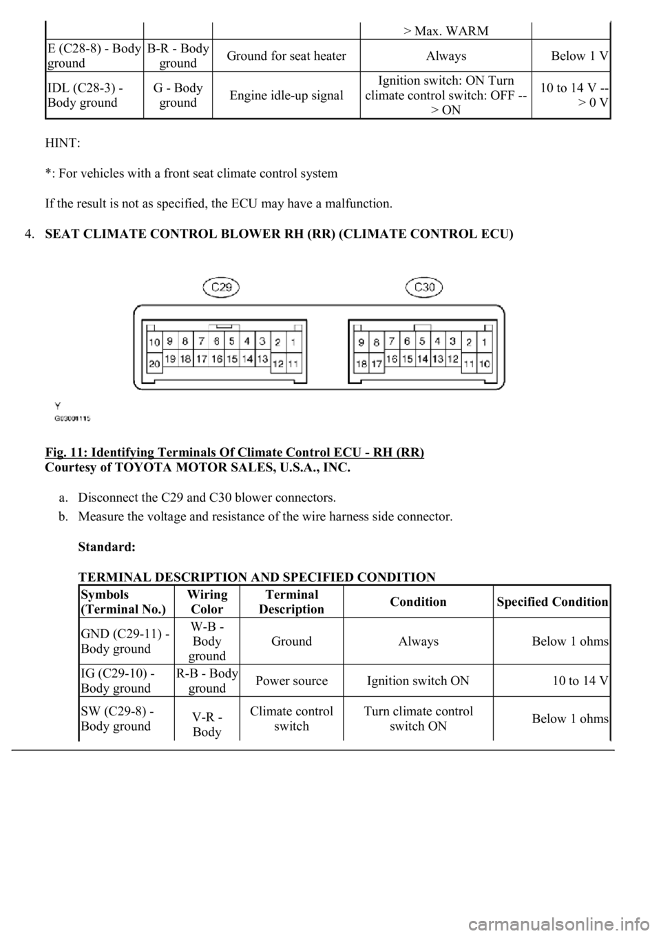
4.SEAT CLIMATE CONTROL BLOWER RH (RR) (CLIMATE CONTROL ECU)
Fig. 11: Identifying Terminals Of Climate Control ECU
- RH (RR)
Courtesy of TOYOTA MOTOR SALES, U.S.A., INC.
a. Disconnect the C29 and C30 blower connectors.
b. Measure the voltage and resistance of the wire harness side connector.
Standard:
TERMINAL DESCRIPTION AND SPECIFIED CONDITION
> Max. WARM
E (C28-8) - Body
groundB-R - Body
groundGround for seat heaterAlwaysBelow 1 V
IDL (C28-3) -
Body groundG - Body
groundEngine idle-up signal
Ignition switch: ON Turn
climate control switch: OFF --
> ON10 to 14 V --
> 0 V
Symbols
(Terminal No.)Wiring
ColorTerminal
DescriptionConditionSpecified Condition
GND (C29-11) -
Body groundW-B -
Body
ground
GroundAlwaysBelow 1 ohms
IG (C29-10) -
Body groundR-B - Body
groundPower sourceIgnition switch ON10 to 14 V
SW (C29-8) -
Body groundV-R -
Body Climate control
switchTurn climate control
switch ONBelow 1 ohms