Page 1666 of 4500

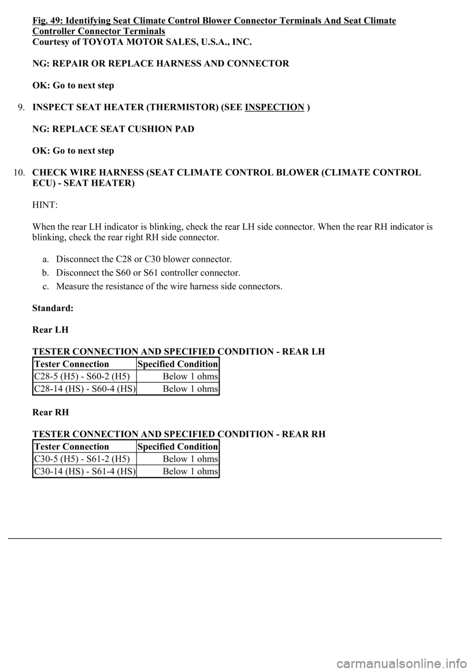
Fig. 49: Identifying Seat Climate Control Blower Connector Terminals And Seat Climate
Controller Connector Terminals
Courtesy of TOYOTA MOTOR SALES, U.S.A., INC.
NG: REPAIR OR REPLACE HARNESS AND CONNECTOR
OK: Go to next step
9.INSPECT SEAT HEATER (THERMISTOR) (SEE INSPECTION
)
NG: REPLACE SEAT CUSHION PAD
OK: Go to next step
10.CHECK WIRE HARNESS (SEAT CLIMATE CONTROL BLOWER (CLIMATE CONTROL
ECU) - SEAT HEATER)
HINT:
When the rear LH indicator is blinking, check the rear LH side connector. When the rear RH indicator is
blinking, check the rear right RH side connector.
a. Disconnect the C28 or C30 blower connector.
b. Disconnect the S60 or S61 controller connector.
c. Measure the resistance of the wire harness side connectors.
Standard:
Rear LH
TESTER CONNECTION AND SPECIFIED CONDITION - REAR LH
Rear RH
TESTER CONNECTION AND SPECIFIED CONDITION - REAR RH
Tester ConnectionSpecified Condition
C28-5 (H5) - S60-2 (H5)Below 1 ohms
C28-14 (HS) - S60-4 (HS)Below 1 ohms
Tester ConnectionSpecified Condition
C30-5 (H5) - S61-2 (H5)Below 1 ohms
C30-14 (HS) - S61-4 (HS)Below 1 ohms
Page 1668 of 4500

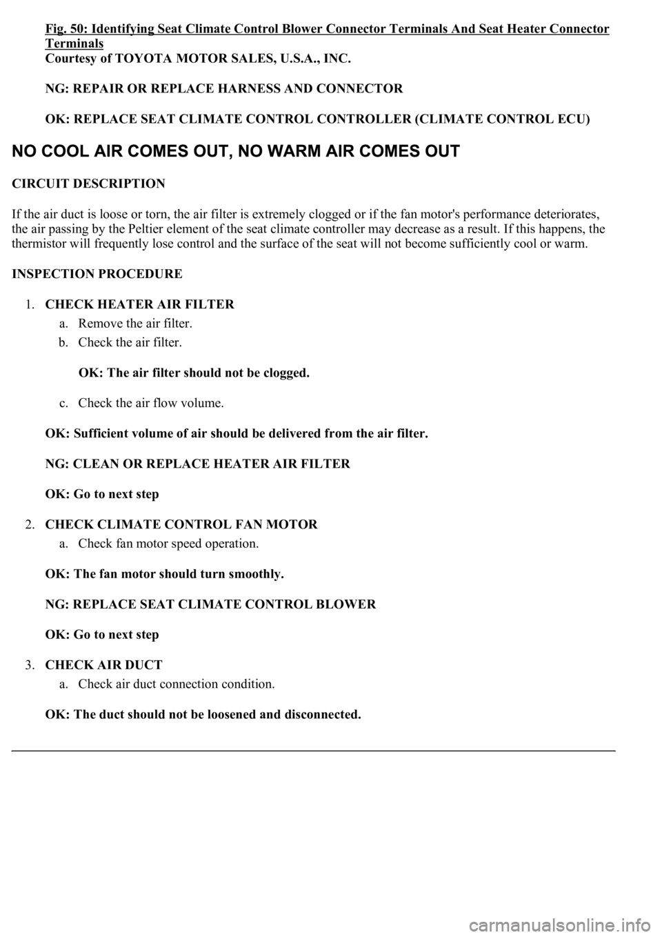
Fig. 50: Identifying Seat Climate Control Blower Connector Terminals And Seat Heater Connector
Terminals
Courtesy of TOYOTA MOTOR SALES, U.S.A., INC.
NG: REPAIR OR REPLACE HARNESS AND CONNECTOR
OK: REPLACE SEAT CLIMATE CONTROL CONTROLLER (CLIMATE CONTROL ECU)
CIRCUIT DESCRIPTION
If the air duct is loose or torn, the air filter is extremely clogged or if the fan motor's performance deteriorates,
the air passing by the Peltier element of the seat climate controller may decrease as a result. If this happens, the
thermistor will frequently lose control and the surface of the seat will not become sufficiently cool or warm.
INSPECTION PROCEDURE
1.CHECK HEATER AIR FILTER
a. Remove the air filter.
b. Check the air filter.
OK: The air filter should not be clogged.
c. Check the air flow volume.
OK: Sufficient volume of air should be delivered from the air filter.
NG: CLEAN OR REPLACE HEATER AIR FILTER
OK: Go to next step
2.CHECK CLIMATE CONTROL FAN MOTOR
a. Check fan motor speed operation.
OK: The fan motor should turn smoothly.
NG: REPLACE SEAT CLIMATE CONTROL BLOWER
OK: Go to next step
3.CHECK AIR DUCT
a. Check air duct connection condition.
OK: The duct should not be loosened and disconnected.
Page 1670 of 4500
b. Measure the voltage of the wire harness side connector.
Standard:
TESTER CONNECTION AND SPECIFIED CONDITION
Fig. 52: Identifying Seat Climate Control Blower Connector Terminals
Courtesy of TOYOTA MOTOR SALES, U.S.A., INC.
NG: Go to step 4
OK: Go to next step
3.CHECK WIRE HARNESS (SEAT CLIMATE CONTROL BLOWER (CLIMATE CONTROL
ECU) - BODY GROUND)
a. Disconnect the C20 blower connector.
Tester ConnectionConditionSpecified Condition
C20-7 (IG) - Body groundIgnition switch ON10 to 14 V
Page 1671 of 4500
b. Measure the resistance of the wire harness side connector.
Standard:
TESTER CONNECTION AND SPECIFIED CONDITION
Fig. 53: Identifying Seat Climate Control Blower Connector Terminals
Courtesy of TOYOTA MOTOR SALES, U.S.A., INC.
NG: REPAIR OR REPLACE HARNESS AND CONNECTOR
OK: REPLACE SEAT CLIMATE CONTROL BLOWER (CLIMATE CONTROL ECU)
4.CHECK WIRE HARNESS (DRIVER SIDE J/B - BATTERY)
a. Disconnect the DJ J/B connector.
b. Measure the voltage of the J/B connector.
Tester ConnectionSpecified Condition
C20-8 (E) - Body groundBelow 1 ohms
Page 1672 of 4500
Standard:
TESTER CONNECTION AND SPECIFIED CONDITION
Fig. 54: Identifying Driver Side J/B Connector Terminals
Courtesy of TOYOTA MOTOR SALES, U.S.A., INC.
NG: Go to step 5
OK: REPAIR OR REPLACE HARNESS AND CONNECTOR (DRIVER SIDE J/B - CLIMATE
CONTROL BLOWER (CLIMATE CONTROL ECU))
5.CHECK WIRE HARNESS (DRIVER SIDE J/B - BATTERY)
a. Disconnect the DA and DF J/B connectors.
Tester ConnectionConditionSpecified Condition
DJ-6 - Body groundIgnition switch ON10 to 14 V
Page 1676 of 4500
NG: REPAIR OR REPLACE HARNESS AND CONNECTOR
OK: Go to next step
7.INSPECT RELAY (Marking: D-IG1)
a. Remove the D-IG1 relay from the driver side J/B.
b. Measure the resistance of the relay.
Standard:
TESTER CONNECTION AND SPECIFIED CONDITION
Fig. 57: Identifying D
-IG1 Relay Terminals And Circuit
Courtesy of TOYOTA MOTOR SALES, U.S.A., INC.
NG: REPLACE RELAY
OK: REPLACE PASSENGER SIDE JUNCTION BLOCK
Tester ConnectionSpecified Condition
3 - 510 kohms or higher
3 - 5Below 1 ohms (when battery voltage is applied to terminal 1 and 2)
Page 1678 of 4500
Fig. 59: Identifying Seat Climate Control Blower Connector Terminals
Courtesy of TOYOTA MOTOR SALES, U.S.A., INC.
NG: REPAIR OR REPLACE HARNESS AND CONNECTOR
OK: Go to next step
3.CHECK WIRE HARNESS (CLIMATE CONTROL BLOWER (CLIMATE CONTROL ECU) -
BODY GROUND)
a. Disconnect the C21 blower connector.
b. Measure the resistance of the wire harness side connector.
Standard:
TESTER CONNECTION AND SPECIFIED CONDITION
C21-7 (IG) - Body groundIgnition switch ON10 to 14 V
Page 1679 of 4500
Fig. 60: Identifying Seat Climate Control Blower Connector Terminals
Courtesy of TOYOTA MOTOR SALES, U.S.A., INC.
NG: REPAIR OR REPLACE HARNESS AND CONNECTOR
OK: REPLACE SEAT CLIMATE CONTROL BLOWER (CLIMATE CONTROL ECU)
4.CHECK WIRE HARNESS (PASSENGER SIDE J/B - BATTERY)
a. Disconnect the PJ J/B connector.
b. Measure the voltage of the J/B connector.
Standard:
TESTER CONNECTION AND SPECIFIED CONDITION
Tester ConnectionSpecified Condition
C20-8 (E) - Body groundBelow 1 ohms