2003 LEXUS LS430 lock
[x] Cancel search: lockPage 2631 of 4500
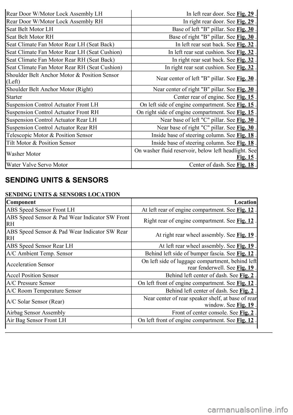
SENDING UNITS & SENSORS LOCATION
Rear Door W/Motor Lock Assembly LHIn left rear door. See Fig. 29 .
Rear Door W/Motor Lock Assembly RHIn right rear door. See Fig. 29 .
Seat Belt Motor LHBase of left "B" pillar. See Fig. 30 .
Seat Belt Motor RHBase of right "B" pillar. See Fig. 30 .
Seat Climate Fan Motor Rear LH (Seat Back)In left rear seat back. See Fig. 32 .
Seat Climate Fan Motor Rear LH (Seat Cushion)In left rear seat cushion. See Fig. 32 .
Seat Climate Fan Motor Rear RH (Seat Back)In right rear seat back. See Fig. 32 .
Seat Climate Fan Motor Rear RH (Seat Cushion)In right rear seat cushion. See Fig. 32 .
Shoulder Belt Anchor Motor & Position Sensor
(Left)Near center of left "B" pillar. See Fig. 30 .
Shoulder Belt Anchor Motor (Right)Near center of right "B" pillar. See Fig. 30 .
StarterCenter rear of engine. See Fig. 15 .
Suspension Control Actuator Front LHOn left side of engine compartment. See Fig. 15 .
Suspension Control Actuator Front RHOn right side of engine compartment. See Fig. 15 .
Suspension Control Actuator Rear LHNear base of left "C" pillar. See Fig. 30 .
Suspension Control Actuator Rear RHNear base of right "C" pillar. See Fig. 30 .
Telescopic Motor & Position SensorInside base of steering column. See Fig. 18 .
Tilt Motor & Position SensorInside base of steering column. See Fig. 18 .
Washer MotorOn washer fluid reservoir, below left headlight. See
Fig. 15
.
Water Valve Servo MotorCenter of dash. See Fig. 18 .
ComponentLocation
ABS Speed Sensor Front LHAt left rear of engine compartment. See Fig. 12 .
ABS Speed Sensor & Pad Wear Indicator SW Front
RHRight rear of engine compartment. See Fig. 12 .
ABS Speed Sensor & Pad Wear Indicator SW Rear
RHAt right rear wheel assembly. See Fig. 19 .
ABS Speed Sensor Rear LHAt left rear wheel assembly. See Fig. 19 .
A/C Ambient Temp. SensorBehind left side of bumper fascia. See Fig. 12 .
Acceleration SensorOn left side of luggage compartment, behind left
rear fenderwell. See Fig. 19
.
Accel Position SensorBehind left center of dash. See Fig. 2 .
A/C Pressure SensorOn left front of engine compartment. See Fig. 12 .
A/C Room Temperature SensorBehind left center of dash. See Fig. 2 .
A/C Solar Sensor (Rear)Near center of rear speaker shelf, at base of rear
window. See Fig. 19
.
Airbag Sensor AssemblyFront of center console. See Fig. 2 .
Air Bag Sensor Front LHOn left front of engine compartment. See Fig. 12 .
Page 2634 of 4500
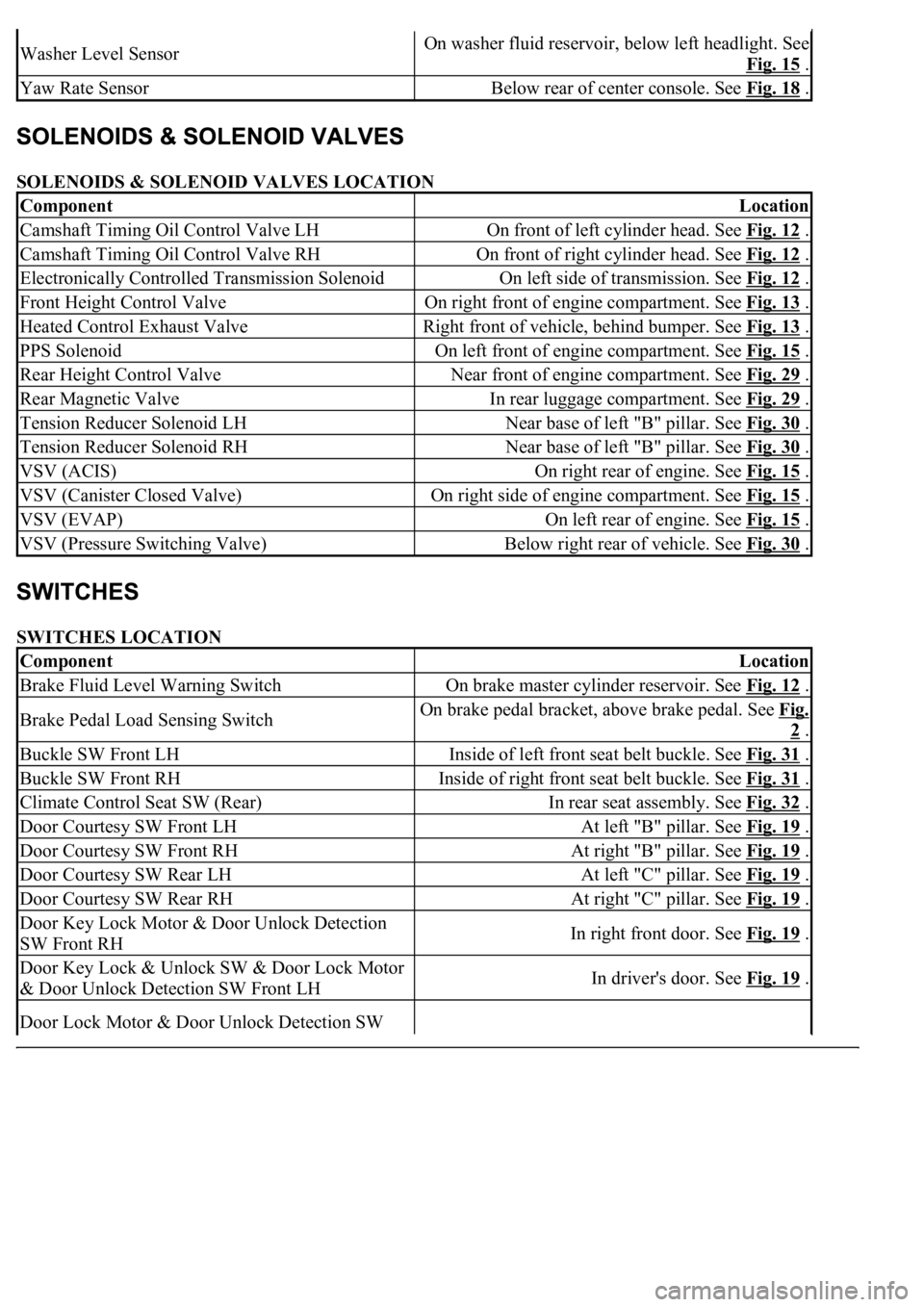
SOLENOIDS & SOLENOID VALVES LOCATION
SWITCHES LOCATION
Washer Level SensorOn washer fluid reservoir, below left headlight. See
Fig. 15
.
Yaw Rate SensorBelow rear of center console. See Fig. 18 .
ComponentLocation
Camshaft Timing Oil Control Valve LHOn front of left cylinder head. See Fig. 12 .
Camshaft Timing Oil Control Valve RHOn front of right cylinder head. See Fig. 12 .
Electronically Controlled Transmission SolenoidOn left side of transmission. See Fig. 12 .
Front Height Control ValveOn right front of engine compartment. See Fig. 13 .
Heated Control Exhaust ValveRight front of vehicle, behind bumper. See Fig. 13 .
PPS SolenoidOn left front of engine compartment. See Fig. 15 .
Rear Height Control ValveNear front of engine compartment. See Fig. 29 .
Rear Magnetic ValveIn rear luggage compartment. See Fig. 29 .
Tension Reducer Solenoid LHNear base of left "B" pillar. See Fig. 30 .
Tension Reducer Solenoid RHNear base of left "B" pillar. See Fig. 30 .
VSV (ACIS)On right rear of engine. See Fig. 15 .
VSV (Canister Closed Valve)On right side of engine compartment. See Fig. 15 .
VSV (EVAP)On left rear of engine. See Fig. 15 .
VSV (Pressure Switching Valve)Below right rear of vehicle. See Fig. 30 .
ComponentLocation
Brake Fluid Level Warning SwitchOn brake master cylinder reservoir. See Fig. 12 .
Brake Pedal Load Sensing SwitchOn brake pedal bracket, above brake pedal. See Fig.
2 .
Buckle SW Front LHInside of left front seat belt buckle. See Fig. 31 .
Buckle SW Front RHInside of right front seat belt buckle. See Fig. 31 .
Climate Control Seat SW (Rear)In rear seat assembly. See Fig. 32 .
Door Courtesy SW Front LHAt left "B" pillar. See Fig. 19 .
Door Courtesy SW Front RHAt right "B" pillar. See Fig. 19 .
Door Courtesy SW Rear LHAt left "C" pillar. See Fig. 19 .
Door Courtesy SW Rear RHAt right "C" pillar. See Fig. 19 .
Door Key Lock Motor & Door Unlock Detection
SW Front RHIn right front door. See Fig. 19 .
Door Key Lock & Unlock SW & Door Lock Motor
& Door Unlock Detection SW Front LHIn driver's door. See Fig. 19 .
Door Lock Motor & Door Unlock Detection SW
Page 2635 of 4500
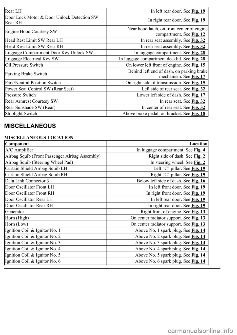
MISCELLANEOUS LOCATION
Rear LHIn left rear door. See Fig. 19 .
Door Lock Motor & Door Unlock Detection SW
Rear RHIn right rear door. See Fig. 19 .
Engine Hood Courtesy SWNear hood latch, on front center of engine
compartment. See Fig. 12
.
Head Rest Limit SW Rear LHIn rear seat assembly. See Fig. 32 .
Head Rest Limit SW Rear RHIn rear seat assembly. See Fig. 32 .
Luggage Compartment Door Key Unlock SWIn luggage compartment. See Fig. 28 .
Luggage Electrical Key SWIn luggage compartment decklid. See Fig. 28 .
Oil Pressure SwitchOn lower left front of engine. See Fig. 15 .
Parking Brake SwitchBehind left end of dash, on parking brake
mechanism. See Fig. 17
.
Park/Neutral Position SwitchOn right side of transmission. See Fig. 15 .
Power Seat Control SW (Rear Seat)Left side of rear seat. See Fig. 32 .
Pressure SwitchLower left side of dash. See Fig. 17 .
Rear Armrest Courtesy SWIn rear seat. See Fig. 32 .
Rear Sunshade SW (Rear)In center of rear seat. See Fig. 32 .
Stoplight SwitchAbove brake pedal, on bracket. See Fig. 18 .
ComponentLocation
A/C AmplifierIn luggage compartment. See Fig. 4 .
Airbag Squib (Front Passenger Airbag Assembly)Right side of dash. See Fig. 2 .
Airbag Squib (Steering Wheel Pad)In steering wheel. See Fig. 2 .
Curtain Shield Airbag Squib LHLeft "C" pillar. See Fig. 19 .
Curtain Shield Airbag Squib RHRight "C" pillar. See Fig. 19 .
Data Link Connector 3Below left side of dash. See Fig. 16 .
Door Oscillator Front LHIn left front door. See Fig. 19 .
Door Oscillator Front RHIn right front door. See Fig. 19 .
Door Oscillator Rear LHIn left rear door. See Fig. 19 .
Door Oscillator Rear RHIn right rear door. See Fig. 19 .
GeneratorRight front of engine. See Fig. 13 .
Horn (High)On center radiator support. See Fig. 13 .
Horn (Low)On center radiator support. See Fig. 13 .
Ignition Coil & Ignitor No. 1Above No. 1 spark plug. See Fig. 14 .
Ignition Coil & Ignitor No. 2Above No. 2 spark plug. See Fig. 14 .
Ignition Coil & Ignitor No. 3Above No. 3 spark plug. See Fig. 14 .
Ignition Coil & Ignitor No. 4Above No. 4 spark plug. See Fig. 14 .
Ignition Coil & Ignitor No. 5Above No. 5 spark plug. See Fig. 14 .
Ignition Coil & Ignitor No. 6Above No. 6 spark plug. See Fig. 14 .
Page 2639 of 4500
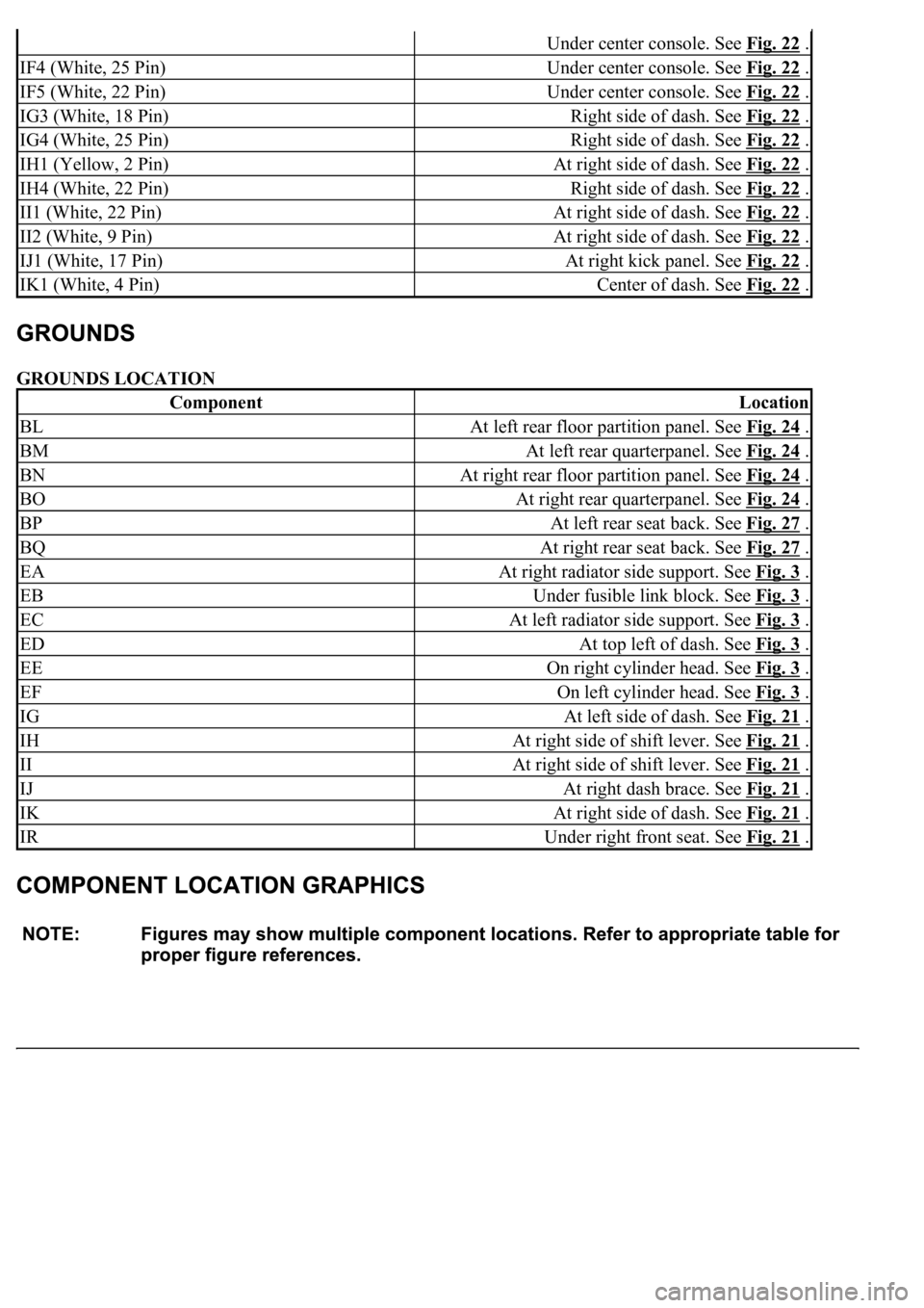
GROUNDS LOCATION
Under center console. See Fig. 22 .
IF4 (White, 25 Pin)Under center console. See Fig. 22 .
IF5 (White, 22 Pin)Under center console. See Fig. 22 .
IG3 (White, 18 Pin)Right side of dash. See Fig. 22 .
IG4 (White, 25 Pin)Right side of dash. See Fig. 22 .
IH1 (Yellow, 2 Pin)At right side of dash. See Fig. 22 .
IH4 (White, 22 Pin)Right side of dash. See Fig. 22 .
II1 (White, 22 Pin)At right side of dash. See Fig. 22 .
II2 (White, 9 Pin)At right side of dash. See Fig. 22 .
IJ1 (White, 17 Pin)At right kick panel. See Fig. 22 .
IK1 (White, 4 Pin)Center of dash. See Fig. 22 .
ComponentLocation
BLAt left rear floor partition panel. See Fig. 24 .
BMAt left rear quarterpanel. See Fig. 24 .
BNAt right rear floor partition panel. See Fig. 24 .
BOAt right rear quarterpanel. See Fig. 24 .
BPAt left rear seat back. See Fig. 27 .
BQAt right rear seat back. See Fig. 27 .
EAAt right radiator side support. See Fig. 3 .
EBUnder fusible link block. See Fig. 3 .
ECAt left radiator side support. See Fig. 3 .
EDAt top left of dash. See Fig. 3 .
EEOn right cylinder head. See Fig. 3 .
EFOn left cylinder head. See Fig. 3 .
IGAt left side of dash. See Fig. 21 .
IHAt right side of shift lever. See Fig. 21 .
IIAt right side of shift lever. See Fig. 21 .
IJAt right dash brace. See Fig. 21 .
IKAt right side of dash. See Fig. 21 .
IRUnder right front seat. See Fig. 21 .
Page 2647 of 4500
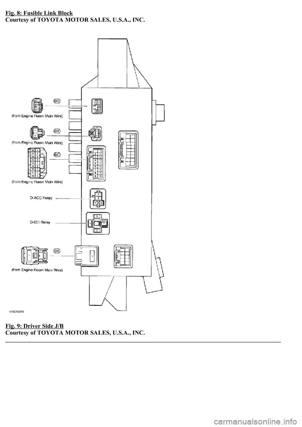
Fig. 8: Fusible Link Block
Courtesy of TOYOTA MOTOR SALES, U.S.A., INC.
Fig. 9: Driver Side J/B
Courtesy of TOYOTA MOTOR SALES, U.S.A., INC.
Page 2671 of 4500
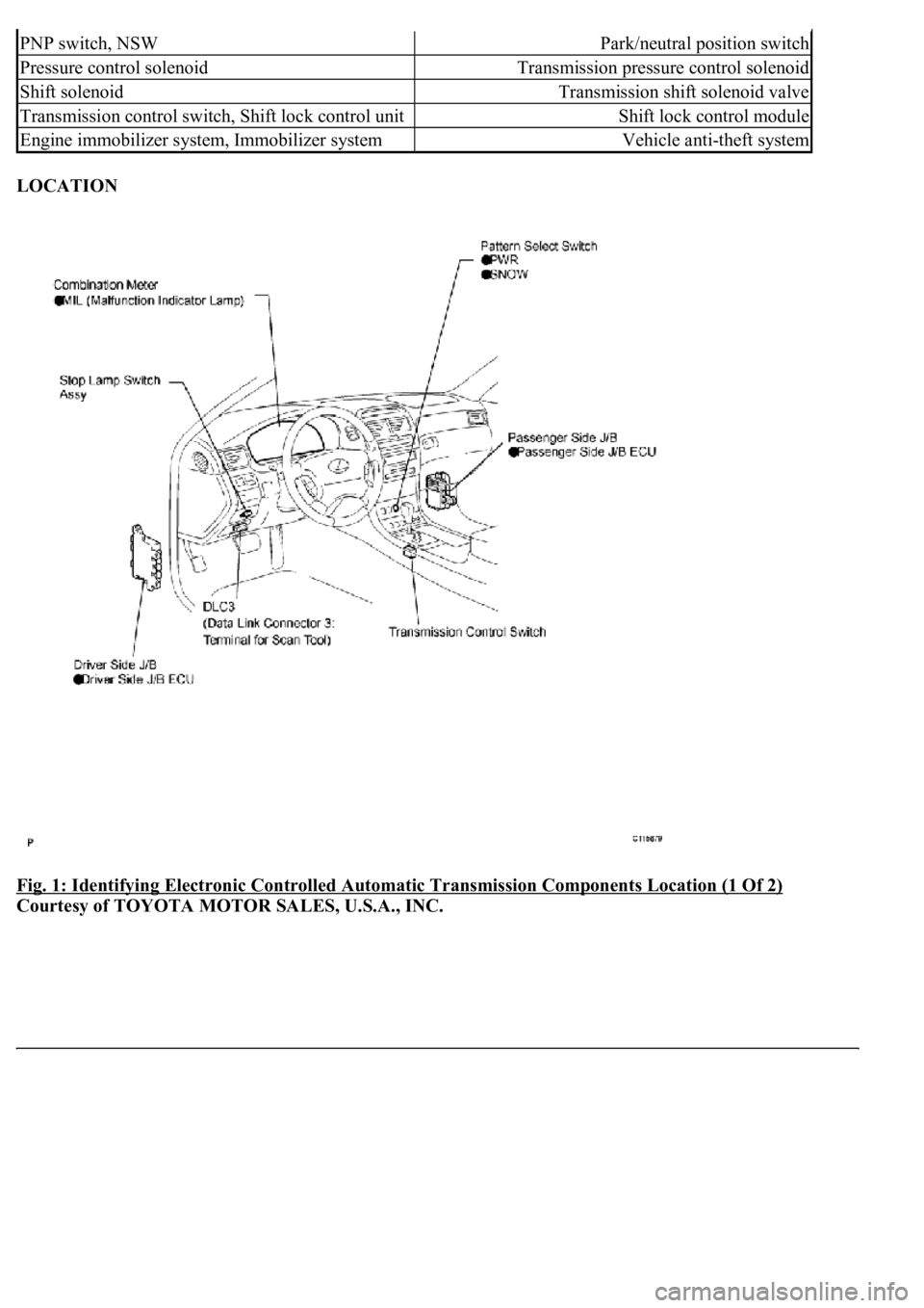
LOCATION
Fig. 1: Identifying Electronic Controlled Automatic Transmission Components Location (1 Of 2)
Courtesy of TOYOTA MOTOR SALES, U.S.A., INC.
PNP switch, NSWPark/neutral position switch
Pressure control solenoidTransmission pressure control solenoid
Shift solenoidTransmission shift solenoid valve
Transmission control switch, Shift lock control unitShift lock control module
Engine immobilizer system, Immobilizer systemVehicle anti-theft system
Page 2679 of 4500
a. D position test:
Shift into the D position and fully depress the accelerator pedal and check the following points.
1. Check up-shift operation.
Check that 1 --> 2,2 --> 3,3 --> 4,4 --> 5 and 5 --> 6th up-shifts take place, and that the shift
points conform to the automatic shift schedule (see SERVICE DATA
).
HINT:
6th and 5th Gear Up-shift Prohibition Control
Engine coolant temperature is 55 °C (131 °F) or less and vehicle speed is at 51 km/h
(32 mph) or less. 4th Gear Up-shift Prohibition Control
Engine coolant temperature is 47 °C (117 °F) or less and vehicle speed is at 49 km/h
(30 mph) or less. Lock-up Prohibition Control
Brake pedal is depressed.
Accelerator pedal is released.
<00280051004a004c005100480003004600520052004f0044005100570003005700480050005300480055004400570058005500480003004c00560003001900130003008300260003000b001400170013000300830029000c0003005200550003004f004800
560056001100030003[
2. Check for shift shock and slip.
Check for shock and slip at the 1 --> 2,2 --> 3, 3 --> 4, 4 --> 5 and 5 --> 6th up-shifts.
3. Check for abnormal noise and vibration.
Check for abnormal noise and vibration when up-shifting from 1 --> 2, 2 --> 3, 3 --> 4, 4 -->
5 and 5 --> 6 while driving with the shift lever in the D position, and also check while driving
in the lock-up condition.
HINT:
The check for the cause of abnormal noise and vibration must be done thoroughly as it could
also be due to loss of balance in the differential, torque converter clutch, etc.
4. Check kick-down operation.
<0026004b00480046004e000300590048004b004c0046004f004800030056005300480048004700560003005a004b0048005100030057004b004800030015005100470003005700520003001400560057000f00030016005500470003005700520003001500
510047000f000300170057004b000300570052000300160055[d, 5th to 4th, and 6th to 5th
kick-downs take place while driving with the shift lever in the D position. Confirm that each
speed is within the applicable vehicle speed range indicated in the automatic shift schedule
(see SERVICE DATA
).
5. Check for abnormal shock and slip at kic
k-down.
Page 2680 of 4500
6. Check the lock-up mechanism.
Drive in the D position (4th, 5th or 6th gear), at a steady speed (lock-up ON).
Lightly depress the accelerator pedal and check that the engine speed does not change
abruptly.
HINT:
There is no lock-up function in the 1st, 2nd and 3rd gears.
If there is a big jump in engine speed, there is no lock-up.
b. S position test
Shift to the S position, depress the accelerator pedal and check the following points:
1. Check shift operation.
While driving in the D position and 6th gear, shift into the S position and back to the D
position. Check that the gear change 6 --> 5 down-shift and 5 --> 6 up-shift can be
performed.
With the shift lever in the S position (while the vehicle is stopped), shift into the "+"
position to check that the shift position on the combination meter changes as follows: 1
--> 2, 2 --> 3, 3 --> 4, 4 --> 5 and 5 --> 6.
While driving in the 5(S) position and 4th gear (at a vehicle speed of approximately 55
to 65 km/h (34 to 40 mph)), shift into the "-" position and check if the 4th gear down-
shift occurs and the engine brake performs properly.
While driving in the 4(S) position and 4th gear (at a vehicle speed of approximately 30
to 40 km/h (19 to 25 mph)), shift into the "-" position and check if the 3rd gear down-
shift occurs and the engine brake performs properly.
While driving in the 3(S) position and 3rd gear (at a vehicle speed of approximately 20
to 30 km/h (12 to 19 mph)), shift into the "-" position and check if the 2nd gear down-
shift occurs and the engine brake performs properly.
<003a004b004c004f0048000300470055004c0059004c0051004a0003004c005100030057004b004800030015000b0036000c0003005300520056004c0057004c00520051000300440051004700030015005100470003004a0048004400550003000b004400
5700030044000300590048004b004c0046004f004800030056[peed of approximately 10
to 20 km/h (6 to 12 mph)), shift into the "-" position and check if the 1st gear down-
shift occurs and the engine brake performs properly.
HINT:
Manual shift (S position) is prohibited under either of the following conditions:
Down-shifting may cause engine overrun.
The driver continuously down-shifts. (Down-shifting to 1st gear may not be performed.)
c. R position test:
Shift into the R position, lightly depress the accelerator pedal, and check that the vehicle moves
backward without any abnormal noise or vibration.