Page 2425 of 4500
WIRELESS DOOR LOCK CONTROL SYSTEM DIAGNOSTIC TROUBLE CODE (DTC)
IDENTIFICATION
DTCDescription
DTC B1242With Smart-Key: WIRELESS DOOR LOCK TUNER CIRCUIT
MALFUNCTION
Without Smart-Key: WIRELESS DOOR LOCK TUNER CIRCUIT
MALFUNCTION
Page 2480 of 4500
Courtesy of TOYOTA MOTOR SALES, U.S.A., INC.
A: REPLACE ECM (SEE REPLACEMENT
)
5.INSPECT DRIVER SIDE J/B
a. Measure the voltage according to the value(s) in the table below.
Fig. 48: Identifying Driver Side Junction Block ECU Connector Terminals
Courtesy of TOYOTA MOTOR SALES, U.S.A., INC.
Standard:
ECU CONNECTOR VOLTAGE RESISTANCE SPECIFICATION
NG: Go to step 6
Pedal conditionTester connectionSpecification
DepressedD3-12 (STPO) - Body ground10 to 14 V
ReleasedD3-12 (STPO) - Body groundBelow 1 V
Page 2481 of 4500
OK: REPAIR OR REPLACE HARNESS OR CONNECTOR (DRIVER SIDE J/B ECU -
ECM)
6.INSPECT DRIVER SIDE J/B
a. Measure the voltage according to the value(s) in the table below.
Fig. 49: Identifying Driver Side Junction Block ECU Connector Terminals
Courtesy of TOYOTA MOTOR SALES, U.S.A., INC.
Standard:
ECU CONNECTOR TERMINALS VOLTAGE SPECIFICATION
NG: REPAIR OR REPLACE HARNESS OR CONNECTOR (STOP LAMP SWITCH -
DRIVER SIDE J/B ECU)
Pedal conditionTester connectionSpecification
DepressedD3-13 (STPI) - Body ground10 to 14 V
ReleasedD3-13 (STPI) - Body groundBelow 1 V
Page 2581 of 4500
Courtesy of TOYOTA MOTOR SALES, U.S.A., INC.
A: REPLACE ECM (SEE REPLACEMENT
)
5.INSPECT DRIVER SIDE J/B
a. Measure the voltage according to the value(s) in the table below.
Fig. 50: Identifying Driver Side Junction Block ECU Connector Terminals
Courtesy of TOYOTA MOTOR SALES, U.S.A., INC.
Standard:
TESTER CONNECTION SPECIFICATION
NG: Go to step 6
Pedal conditionTester connectionSpecification
DepressedD3-12 (STPO) - Body ground10 to 14V
ReleasedD3-12 (STPO) - Body groundBelow 1 V
Page 2582 of 4500
OK: REPAIR OR REPLACE HARNESS OR CONNECTOR (DRIVER SIDE J/B ECU - ECM)
6.INSPECT DRIVER SIDE J/B
a. Measure the voltage according to the value(s) in the table below.
Fig. 51: Identifying Driver Side Junction Block ECU Connector Terminals
Courtesy of TOYOTA MOTOR SALES, U.S.A., INC.
Standard:
ECU CONNECTOR TERMINALS VOLTAGE SPECIFICATION
NG: REPAIR OR REPLACE HARNESS OR CONNECTOR (STOP LAMP SWITCH - DRIVER
SIDE J/B ECU)
OK: REPLACE DRIVER SIDE J/B
Pedal conditionTester connectionSpecification
DepressedD3-13 (STPI) - Body ground10 to 14V
ReleasedD3-13 (STPI) - Body groundBelow 1 V
Page 2627 of 4500

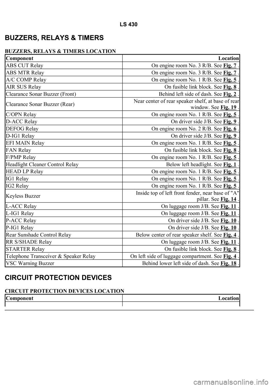
BUZZERS, RELAYS & TIMERS LOCATION
CIRCUIT PROTECTION DEVICES LOCATION
ComponentLocation
ABS CUT RelayOn engine room No. 3 R/B. See Fig. 7 .
ABS MTR RelayOn engine room No. 3 R/B. See Fig. 7 .
A/C COMP RelayOn engine room No. 1 R/B. See Fig. 5 .
AIR SUS RelayOn fusible link block. See Fig. 8 .
Clearance Sonar Buzzer (Front)Behind left side of dash. See Fig. 2 .
Clearance Sonar Buzzer (Rear)Near center of rear speaker shelf, at base of rear
window. See Fig. 19
.
C/OPN RelayOn engine room No. 1 R/B. See Fig. 5 .
D-ACC RelayOn driver side J/B. See Fig. 9 .
DEFOG RelayOn engine room No. 2 R/B. See Fig. 6 .
D-IG1 RelayOn driver side J/B. See Fig. 9 .
EFI MAIN RelayOn engine room No. 1 R/B. See Fig. 5 .
FAN RelayOn fusible link block. See Fig. 8 .
F/PMP RelayOn engine room No. 1 R/B. See Fig. 5 .
Headlight Cleaner Control RelayBelow left headlight. See Fig. 1 .
HEAD LP RelayOn engine room No. 1 R/B. See Fig. 5 .
IG1 RelayOn engine room No. 1 R/B. See Fig. 5 .
IG2 RelayOn engine room No. 1 R/B. See Fig. 5 .
Keyless BuzzerInside top of left front fender, near base of "A"
pillar. See Fig. 14
.
L-ACC RelayOn luggage room J/B. See Fig. 11 .
L-IG1 RelayOn luggage room J/B. See Fig. 11 .
P-ACC RelayOn driver side J/B. See Fig. 10 .
P-IG1 RelayOn driver side J/B. See Fig. 10 .
Rear Sunshade Control RelayBelow center of rear speaker shelf. See Fig. 4 .
RR S/SHADE RelayOn luggage room J/B. See Fig. 11 .
STARTER RelayOn fusible link block. See Fig. 8 .
Telephone Transceiver & Speaker RelayOn left side of luggage compartment. See Fig. 4 .
VSC Warning BuzzerBehind lower left side of dash. See Fig. 18 .
ComponentLocation
Page 2628 of 4500

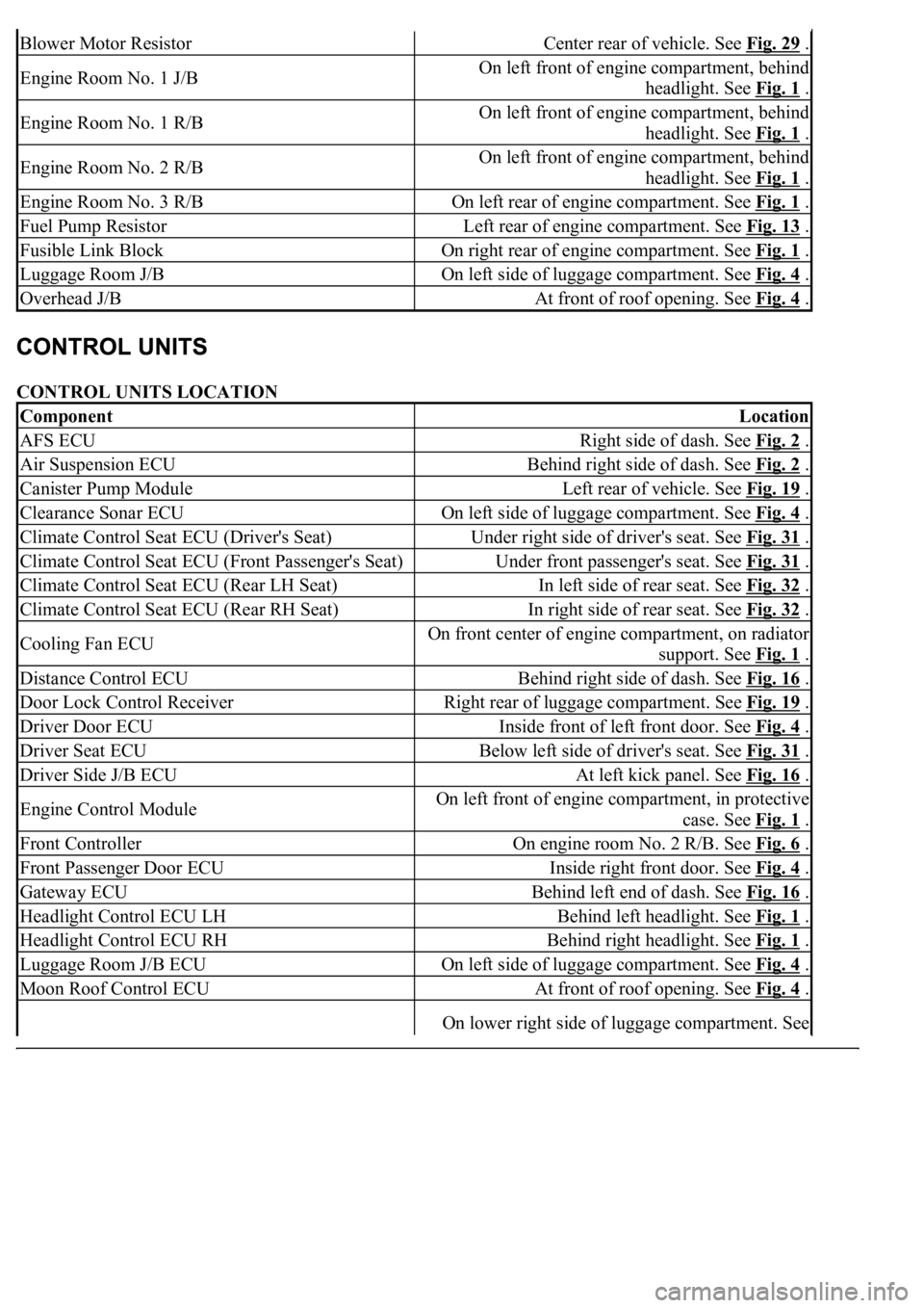
CONTROL UNITS LOCATION
Blower Motor ResistorCenter rear of vehicle. See Fig. 29 .
Engine Room No. 1 J/BOn left front of engine compartment, behind
headlight. See Fig. 1
.
Engine Room No. 1 R/BOn left front of engine compartment, behind
headlight. See Fig. 1
.
Engine Room No. 2 R/BOn left front of engine compartment, behind
headlight. See Fig. 1
.
Engine Room No. 3 R/BOn left rear of engine compartment. See Fig. 1 .
Fuel Pump ResistorLeft rear of engine compartment. See Fig. 13 .
Fusible Link BlockOn right rear of engine compartment. See Fig. 1 .
Luggage Room J/BOn left side of luggage compartment. See Fig. 4 .
Overhead J/BAt front of roof opening. See Fig. 4 .
ComponentLocation
AFS ECURight side of dash. See Fig. 2 .
Air Suspension ECUBehind right side of dash. See Fig. 2 .
Canister Pump ModuleLeft rear of vehicle. See Fig. 19 .
Clearance Sonar ECUOn left side of luggage compartment. See Fig. 4 .
Climate Control Seat ECU (Driver's Seat)Under right side of driver's seat. See Fig. 31 .
Climate Control Seat ECU (Front Passenger's Seat)Under front passenger's seat. See Fig. 31 .
Climate Control Seat ECU (Rear LH Seat)In left side of rear seat. See Fig. 32 .
Climate Control Seat ECU (Rear RH Seat)In right side of rear seat. See Fig. 32 .
Cooling Fan ECUOn front center of engine compartment, on radiator
support. See Fig. 1
.
Distance Control ECUBehind right side of dash. See Fig. 16 .
Door Lock Control ReceiverRight rear of luggage compartment. See Fig. 19 .
Driver Door ECUInside front of left front door. See Fig. 4 .
Driver Seat ECUBelow left side of driver's seat. See Fig. 31 .
Driver Side J/B ECUAt left kick panel. See Fig. 16 .
Engine Control ModuleOn left front of engine compartment, in protective
case. See Fig. 1
.
Front ControllerOn engine room No. 2 R/B. See Fig. 6 .
Front Passenger Door ECUInside right front door. See Fig. 4 .
Gateway ECUBehind left end of dash. See Fig. 16 .
Headlight Control ECU LHBehind left headlight. See Fig. 1 .
Headlight Control ECU RHBehind right headlight. See Fig. 1 .
Luggage Room J/B ECUOn left side of luggage compartment. See Fig. 4 .
Moon Roof Control ECUAt front of roof opening. See Fig. 4 .
On lower right side of luggage compartment. See
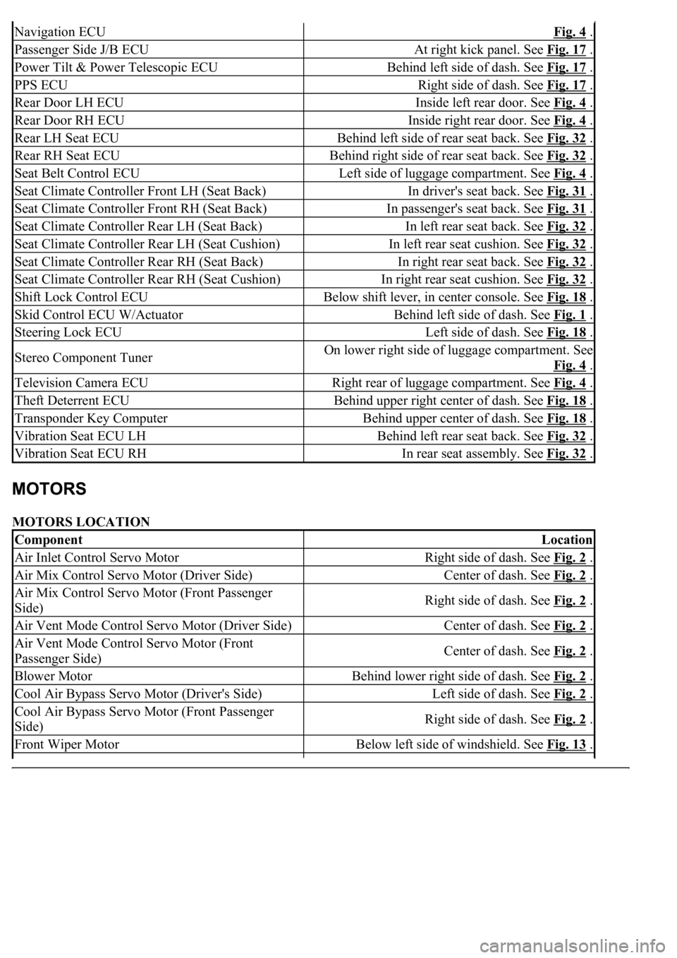
Page 2629 of 4500

MOTORS LOCATION
Navigation ECUFig. 4 .
Passenger Side J/B ECUAt right kick panel. See Fig. 17 .
Power Tilt & Power Telescopic ECUBehind left side of dash. See Fig. 17 .
PPS ECURight side of dash. See Fig. 17 .
Rear Door LH ECUInside left rear door. See Fig. 4 .
Rear Door RH ECUInside right rear door. See Fig. 4 .
Rear LH Seat ECUBehind left side of rear seat back. See Fig. 32 .
Rear RH Seat ECUBehind right side of rear seat back. See Fig. 32 .
Seat Belt Control ECULeft side of luggage compartment. See Fig. 4 .
Seat Climate Controller Front LH (Seat Back)In driver's seat back. See Fig. 31 .
Seat Climate Controller Front RH (Seat Back)In passenger's seat back. See Fig. 31 .
Seat Climate Controller Rear LH (Seat Back)In left rear seat back. See Fig. 32 .
Seat Climate Controller Rear LH (Seat Cushion)In left rear seat cushion. See Fig. 32 .
Seat Climate Controller Rear RH (Seat Back)In right rear seat back. See Fig. 32 .
Seat Climate Controller Rear RH (Seat Cushion)In right rear seat cushion. See Fig. 32 .
Shift Lock Control ECUBelow shift lever, in center console. See Fig. 18 .
Skid Control ECU W/ActuatorBehind left side of dash. See Fig. 1 .
Steering Lock ECULeft side of dash. See Fig. 18 .
Stereo Component TunerOn lower right side of luggage compartment. See
Fig. 4
.
Television Camera ECURight rear of luggage compartment. See Fig. 4 .
Theft Deterrent ECUBehind upper right center of dash. See Fig. 18 .
Transponder Key ComputerBehind upper center of dash. See Fig. 18 .
Vibration Seat ECU LHBehind left rear seat back. See Fig. 32 .
Vibration Seat ECU RHIn rear seat assembly. See Fig. 32 .
ComponentLocation
Air Inlet Control Servo MotorRight side of dash. See Fig. 2 .
Air Mix Control Servo Motor (Driver Side)Center of dash. See Fig. 2 .
Air Mix Control Servo Motor (Front Passenger
Side)Right side of dash. See Fig. 2 .
Air Vent Mode Control Servo Motor (Driver Side)Center of dash. See Fig. 2 .
Air Vent Mode Control Servo Motor (Front
Passenger Side)Center of dash. See Fig. 2 .
Blower MotorBehind lower right side of dash. See Fig. 2 .
Cool Air Bypass Servo Motor (Driver's Side)Left side of dash. See Fig. 2 .
Cool Air Bypass Servo Motor (Front Passenger
Side)Right side of dash. See Fig. 2 .
Front Wiper MotorBelow left side of windshield. See Fig. 13 .