Page 2681 of 4500
d. P position test:
Stop the vehicle on a grade (more than 5°) and after shifting into the P position, release the parking
brake. Then, check that the parking lock pawl holds the vehicle in place.
MECHANICAL SYSTEM TESTS
1.PERFORM MECHANICAL SYSTEM TESTS
a. Measure the stall speed.
The object of this test is to check the overall performance of the transmission and engine by
measuring the stall speeds in the D and R positions.
1. Chock the 4 wheels.
2. Connect an OBD II scan tool or hand-held tester to the DLC3.
3. Fully apply the parking brake.
4. Keep your left foot pressed firmly on the brake pedal.
5. Start the engine.
6. Shift into the D position. Press all the way down on the accelerator pedal with your right
foot.
7. Quickly read the stall speed at this time.
Stall speed: 2,400 +/- 150 rpm
8. Do the same test in the R position.
Stall speed: 2,400 +/- 150 rpm
Evaluation:
Page 2695 of 4500

a. Perform this drive pattern as one method to simulate the detection conditions of the ECT
malfunctions. (The DTCs may not be detected due the actual driving conditions. And some codes
may not be detected through this drive pattern.)
HINT:
Preparation for driving
Warm up the engine sufficiently. (Engine coolant temperature is 60 °C (140 °F) or higher)
Drive the vehicle when the atmospheric temperature is -10 °C (14 °F) or higher. (Malfunction is not
detected when the atmospheric temperature is -10 °C (14 °F) or less)
Notice in driving
Drive the vehicle through all gears.
Stop --> 1st --> 2nd --> 3rd --> 4th --> 5th --> 6th --> 6th (lock-up ON).
Perform engine brake test in the S position.
While driving in the 6(S) position and 6th gear lock-up, shift into the "-" position and down-shift
<0049005500520050000300190057004b000300570052000300180057004b000f000300180057004b000300570052000300170057004b000f000300170057004b0003005700520003001600550047000f000300160055004700030057005200030015005100
47000f00030015005100470003005700520003001400560057[.
<0026004b00480046004e00030057004b0044005700030057004b0048000300480051004a004c005100480003004500550044004e00480003005300480055004900520055005000560003005300550052005300480055004f005c0003005a004b0048005100
48005900480055000300470052005a005100100056004b004c[ft takes place.
Repeat the above driving pattern three times or more.
Page 2696 of 4500
Fig. 19: Identifying Vehicle Speed Pattern
Courtesy of TOYOTA MOTOR SALES, U.S.A., INC.
HINT:
*1: Drive at such a speed in the uppermost gear, to engage lock-up. The vehicle can be driven at a speed
lower than that in the above diagram under the lock-up condition.
PROBLEM SYMPTOMS TABLE
HINT:
If a normal code is displayed during the diagnostic trouble code check although the trouble still occurs, check
the electrical circuits for each symptom in the order given in the following charts.
The Matrix Chart is divided into 2 chapters.
1.Chapter 1: Electronic Circuit Matrix Chart
Refer to the table below when the trouble cause is considered to be electrical.
If the instruction "Proceed to next circuit inspection shown on matrix chart" is given in the flow
chart of each circuit, proceed to the circuit with the next highest number in the table to continue the
check.
Page 2705 of 4500
Fig. 27: Identifying Waveform 2
Courtesy of TOYOTA MOTOR SALES, U.S.A., INC.
Reference:
WAVEFORM 2 REFERENCE TABLE
Waveform 3
TerminalSLU+ - SLU-
Tool setting5V/DIV, 1ms/DIV
Vehicle condition5th (lock-up) or 6th (lock-up) gear
Page 2736 of 4500
Fig. 53: Park/Neutral Position Switch Reference Chart
Courtesy of TOYOTA MOTOR SALES, U.S.A., INC.
NG: REPLACE PARK/NEUTRAL POSITION SWITCH ASSY (See step 25 on
REPLACEMENT
)
OK: Go to next step
2.INSPECT TRANSMISSION CONTROL SWITCH
a. Connect the park/neutral position switch connector.
b. Disconnect the transmission control switch connector of shift lock control unit assy.
c. Measure resistance according to the value(s) in the table below when the shift lever is moved to
each position.
Page 2738 of 4500
Fig. 55: Transmission Control Switch Reference Chart
Courtesy of TOYOTA MOTOR SALES, U.S.A., INC.
NG: REPLACE TRANSMISSION CONTROL SWITCH (See COMPONENTS
)
OK: Go to next step
3.CHECK HARNESS AND CONNECTOR (PARK/NEUTRAL POSITION SWITCH -ECM)
a. Connect the transmission control switch connector of shift lock control unit assy.
b. Turn the ignition switch to the ON position, and measure the voltage according to the value(s) in
the table below when the shift lever is moved to each position.
Page 2754 of 4500
MONITOR STRATEGY
MONITOR STRATEGY TABLE
TYPICAL ENABLING CONDITIONS
TYPICAL ENABLING CONDITIONS TABLE
TYPICAL MALFUNCTION THRESHOLDS
TYPICAL MALFUNCTION THRESHOLDS TABLE
COMPONENT OPERATING RANGE
COMPONENT OPERATING RANGE TABLE
WIRING DIAGRAM
Related DTCsP0717: Speed sensor (NT)/Verify pulse input
Required sensors/ComponentsSpeed sensor (NT)
Frequency of operationContinuous
Duration5 sec.
MIL operationImmediate
Sequence of operationNone
The monitor will run whenever this DTC is not
present.See LIST OF DISABLE A MONITOR
Shift changeShift change is completed and before starting next
shift change operation
ECM selected gear4th, 5th or 6th
Output shaft rpm1,000 rpm or more
NSW switchOFF
R switchOFF
EngineRunning
Sensor signal rpmLess than 300 rpm
Speed sensor (NT)Input speed is equal to engine speed when lock-up
ON.
Page 2759 of 4500

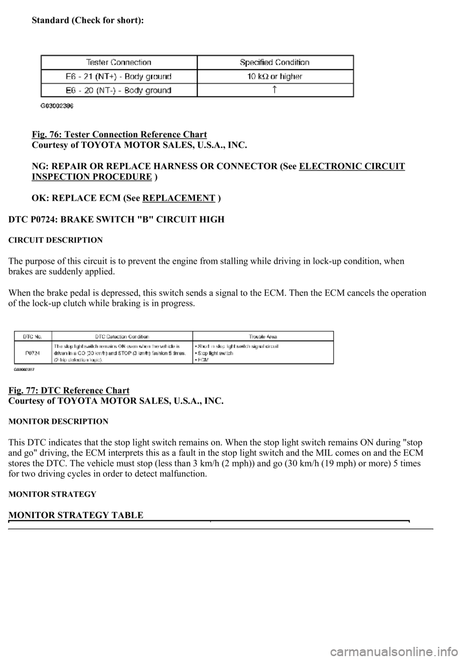
Standard (Check for short):
Fig. 76: Tester Connection Reference Chart
Courtesy of TOYOTA MOTOR SALES, U.S.A., INC.
NG: REPAIR OR REPLACE HARNESS OR CONNECTOR (See ELECTRONIC CIRCUIT
INSPECTION PROCEDURE )
OK: REPLACE ECM (See REPLACEMENT
)
DTC P0724: BRAKE SWITCH "B" CIRCUIT HIGH
CIRCUIT DESCRIPTION
The purpose of this circuit is to prevent the engine from stalling while driving in lock-up condition, when
brakes are suddenly applied.
When the brake pedal is depressed, this switch sends a signal to the ECM. Then the ECM cancels the operation
of the lock-up clutch while braking is in progress.
Fig. 77: DTC Reference Chart
Courtesy of TOYOTA MOTOR SALES, U.S.A., INC.
MONITOR DESCRIPTION
This DTC indicates that the stop light switch remains on. When the stop light switch remains ON during "stop
and go" driving, the ECM interprets this as a fault in the stop light switch and the MIL comes on and the ECM
stores the DTC. The vehicle must stop (less than 3 km/h (2 mph)) and go (30 km/h (19 mph) or more) 5 times
for two driving cycles in order to detect malfunction.
MONITOR STRATEGY
MONITOR STRATEGY TABLE