Page 126 of 4500
TESTER CONNECTION SPECIFIED CONDITION
NG: REPAIR OR REPLACE HARNESS OR CONNECTOR (GND TERMINAL - BODY
GROUND)
Fig. 92: Identifying Skid Control ECU Connector Terminals
Courtesy of TOYOTA MOTOR SALES, U.S.A., INC.
OK: CHECK AND REPAIR HARNESS AND CONNECTOR (IG1 TERMINAL - BATTERY)
CIRCUIT DESCRIPTION
Master c
ylinder pressure sensor is connected to the skid control ECU in the actuator.
Tester ConnectionSpecified Condition
S42-32 (GND) - Body groundBelow 1ohms
Page 131 of 4500
Fig. 98: Pedal Condition Reference Table
Courtesy of TOYOTA MOTOR SALES, U.S.A., INC.
NG: Go to step 6
HINT:
Check the stop lamp bulb as it may have burnt out.
OK:
2.INSPECT MULTIPLEX COMMUNICATION SYSTEM (SEE HOW TO PROCEED WITH
TROUBLESHOOTING )
a. Is DTC output Multiplex communication system?
Result:
DTC OUTPUT DESCRIPTION
B: REPAIR MULTIPLEX COMMUNICATION SYSTEM
A: Go to next step
3.CHECK HARNESS AND CONNECTOR (STP1 TERMINAL VOLTAGE OF DRIVER SIDE J/B
ECU)
a. Disconnect the driver side J/B ECU connector.
b. Measure the voltage according to the value (s) in the table below.
Standard:
TESTER CONNECTION SPECIFIED CONDITION
DTC is not outputA
TDC is outputB
Tester ConnectionSwitch ConditionSpecified Condition
D3-13 (STP1) - Body ground Brakepedal depressed8 to 14 V
D3-13 (STP1) - Body groundBrake pedal releasedBelow 1 V
Page 138 of 4500
Fig. 102: Identifying Stop Lamp Switch Connector And Driver Side J/B Connector Terminals
Courtesy of TOYOTA MOTOR SALES, U.S.A., INC.
NG: REPAIR OR REPLACE HARNESS OR CONNECTOR
OK: Go to next step
8.CHECK HARNESS AND CONNECTOR (STPA OF DRIVER SIDE J/B ECU - STP OF SKID
CONTROL ECU)
a. Disconnect the driver side J/B connector and skid control ECU connector.
b. Measure the resistance according to the value (s) in the table below.
Standard:
TESTER CONNECTION SPECIFIED CONDITION
Standard:
TESTER CONNECTION SPECIFIED CONDITION
Tester ConnectionSpecified Condition
D5-3 (STPA) - S42-27 (STP)Below 1 ohms
Tester ConnectionSpecified Condition
S42-27 (STP) - Body ground1 Mohms or higher
Page 142 of 4500
VEHICLE CONDITION / TEST DETAILS
OK: Go to next step
The operation sound of the ABS motor is heard.
OK: Go to step 2
NG: REPLACE ABS & TRACTION ACTUATOR ASSY (SEE REPLACEMENT
)
2.INSPECT HARNESS AND CONNECTOR (GND2 OF SKID CONTROL ECU AND BODY
GROUND)
a. Disconnect the skid control ECU connector.
b. Measure the resistance according to the value (s) in the table below.
Standard:
TESTER CONNECTION SPECIFIED CONDITION
NG: REPAIR OR REPLACE HARNESS OR CONNECTOR
ItemVehicle Condition / Test DetailsVehicle Condition / Test Details
Turns ABS MOT RELAYABS motor relay / ON or OFFON: Motor relay ON
Tester ConnectionSpecified Condition
S42-1 (GND2) - Body groundBelow 1 ohms
Page 145 of 4500

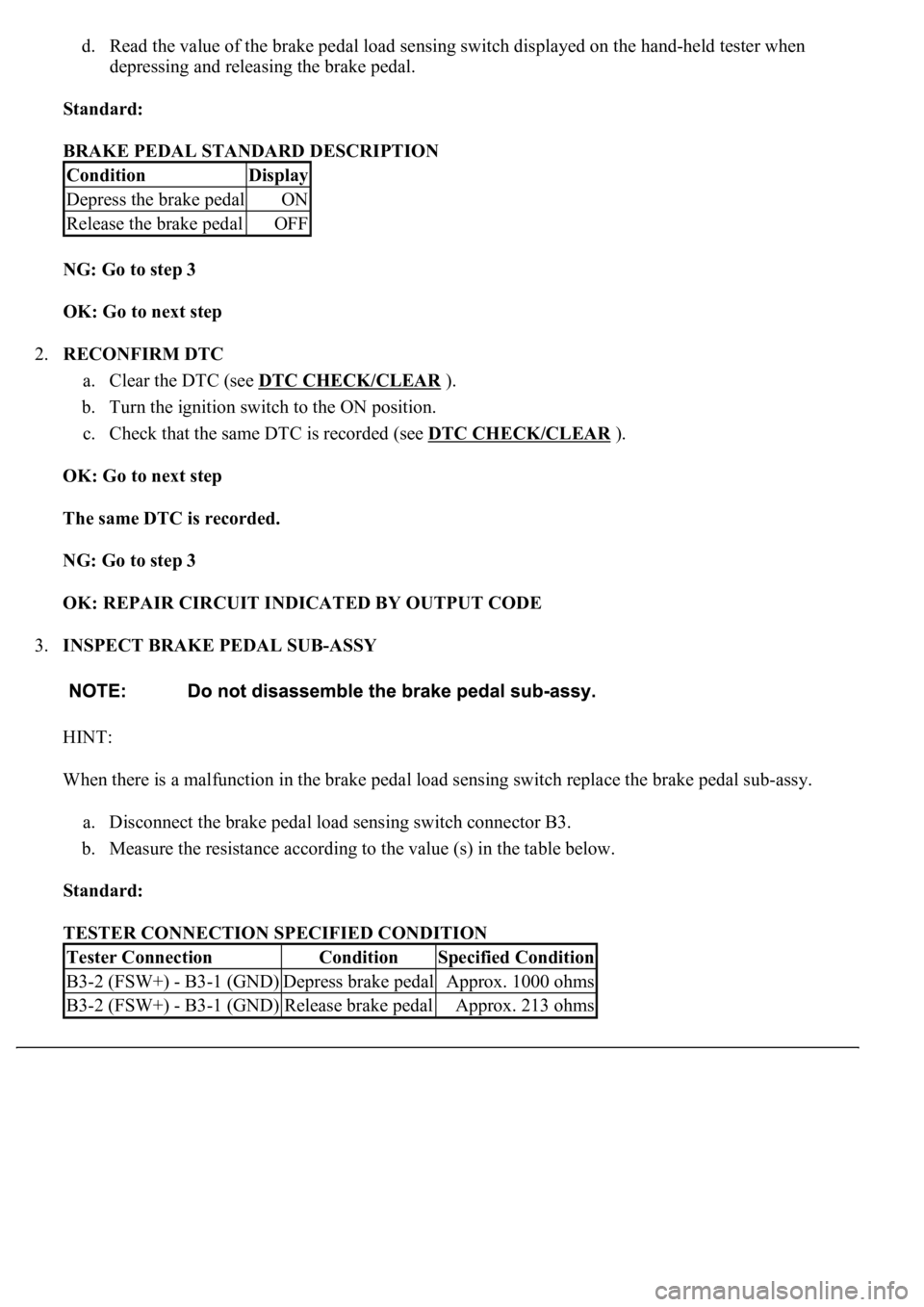
d. Read the value of the brake pedal load sensing switch displayed on the hand-held tester when
depressing and releasing the brake pedal.
Standard:
BRAKE PEDAL STANDARD DESCRIPTION
NG: Go to step 3
OK: Go to next step
2.RECONFIRM DTC
a. Clear the DTC (see DTC CHECK/CLEAR
).
b. Turn the ignition switch to the ON position.
c. Check that the same DTC is recorded (see DTC CHECK/CLEAR
).
OK: Go to next step
The same DTC is recorded.
NG: Go to step 3
OK: REPAIR CIRCUIT INDICATED BY OUTPUT CODE
3.INSPECT BRAKE PEDAL SUB-ASSY
HINT:
When there is a malfunction in the brake pedal load sensing switch replace the brake pedal sub-assy.
a. Disconnect the brake pedal load sensing switch connector B3.
b. Measure the resistance according to the value (s) in the table below.
Standard:
TESTER CONNECTION SPECIFIED CONDITION
ConditionDisplay
Depress the brake pedalON
Release the brake pedalOFF
Tester ConnectionConditionSpecified Condition
B3-2 (FSW+) - B3-1 (GND)Depress brake pedalApprox. 1000 ohms
B3-2 (FSW+) - B3-1 (GND)Release brake pedalApprox. 213 ohms
Page 147 of 4500
Courtesy of TOYOTA MOTOR SALES, U.S.A., INC.
OK: Go to next step
4.CHECK HARNESS AND CONNECTOR (SKID CONTROL ECU - BRAKE PEDAL LOAD
SENSING SWITCH)
a. Disconnect the skid control ECU connector S42 and the brake pedal load sensing switch connector
B3.
b. Measure the resistance according to the value (s) in the table below.
Standard:
TESTER CONNECTION SPECIFIED CONDITION
c. Measure the resistance according to the value (s) in the table below.
Standard:
TESTER CONNECTION SPECIFIED CONDITION
NG: REPAIR OR REPLACE HARNESS OR CONNECTOR
Tester ConnectionSpecified Condition
S42-7 (FSW) - B3-2 (FSW)Below 1 ohms
Tester ConnectionSpecified Condition
S42-7 (FSW) - Body ground1 Mohms or higher
Page 150 of 4500
INSPECTION PROCEDURE
1.CHECK DTC
a. Is DTC output for ABS, CAN and/or MPX?
OK: Go to next step
DTC OUTPUT DESCRIPTION
B: REPAIR CIRCUIT INDICATED BY OUTPUT CODE
A: Go to next step
2.INSPECT SKID CONTROL ECU CONNECTOR (SEE REPLACEMENT
)
a. Check the ECU connectors connecting condition.
OK: Go to next step
The connector is securely connected.
NG: CONNECT CONNECTOR TO ECU CORRECTLY
OK: Go to next step
3.INSPECT BATTERY
a. Check the battery voltage.
Standard:
Voltage: 10 to 14 V
NG: INSPECT CHARGING SYSTEM (SEE ON
-VEHICLE INSPECTION )
OK: Go to next step
4.INSPECT SKID CONTROL ECU TERMINAL VOLTAGE (IG1 TERMINAL)
a. Connect the hand-held tester to the DLC3.
b. Start the engine.
c. Select the DATA LIST mode on the han
d-held tester.
DTC is not outputA
DTC is outputB
Page 151 of 4500
<0029004c004a00110003001400140016001d0003002c0057004800500003003000480044005600580055004800500048005100570003002c0057004800500003003500440051004a0048000300310052005500500044004f00030026005200510047004c00
57004c00520051[
Courtesy of TOYOTA MOTOR SALES, U.S.A., INC.
d. Read the voltage condition output from the ECU displayed on the hand-held tester.
OK: Go to next step
"Normal" is displayed.
NG: REPAIR OR REPLACE HARNESS OR CONNECTOR
OK: Go to next step
5.CHECK HARNESS AND CONNECTOR (SKID CONTROL ECU - BODY GROUND)
a. Disconnect the skid control ECU connector.
b. Measure the resistance according to the value (s) in the table below.
Standard:
TESTER CONNECTION SPECIFIED CONDITION
Tester ConnectionSpecified Condition
S42-32 (GND) - Body groundBelow 1 ohms