Page 183 of 4500

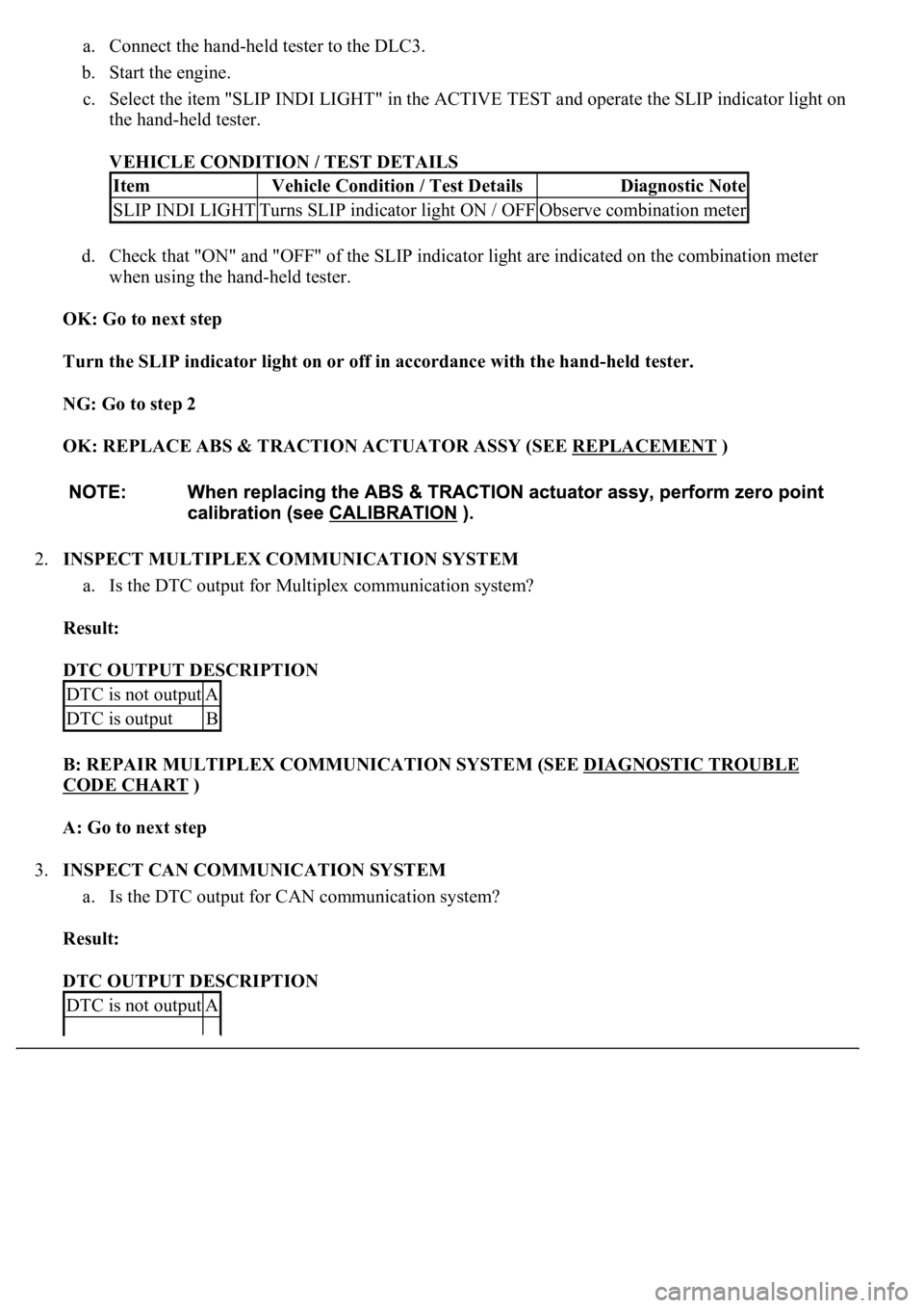
a. Connect the hand-held tester to the DLC3.
b. Start the engine.
c. Select the item "SLIP INDI LIGHT" in the ACTIVE TEST and operate the SLIP indicator light on
the hand-held tester.
VEHICLE CONDITION / TEST DETAILS
d. Check that "ON" and "OFF" of the SLIP indicator light are indicated on the combination meter
when using the hand-held tester.
OK: Go to next step
Turn the SLIP indicator light on or off in accordance with the hand-held tester.
NG: Go to step 2
OK: REPLACE ABS & TRACTION ACTUATOR ASSY (SEE REPLACEMENT
)
2.INSPECT MULTIPLEX COMMUNICATION SYSTEM
a. Is the DTC output for Multiplex communication system?
Result:
DTC OUTPUT DESCRIPTION
B: REPAIR MULTIPLEX COMMUNICATION SYSTEM (SEE DIAGNOSTIC TROUBLE
CODE CHART )
A: Go to next step
3.INSPECT CAN COMMUNICATION SYSTEM
a. Is the DTC output for CAN communication system?
Result:
DTC OUTPUT DESCRIPTION
ItemVehicle Condition / Test DetailsDiagnostic Note
SLIP INDI LIGHTTurns SLIP indicator light ON / OFFObserve combination meter
DTC is not outputA
DTC is outputB
DTC is not outputA
Page 189 of 4500
Standard:
TESTER CONNECTION SPECIFIED CONDITION
NG: REPAIR OR REPLACE HARNESS OR CONNECTOR
OK: REPLACE ABS & TRACTION ACTUATOR ASSY (SEE REPLACEMENT
)
CIRCUIT DESCRIPTION
Connecting terminals TC and CG of the DLC3 causes the ECU to display the DTC by blinking the ABS
warning light.
WIRING DIAGRAM
Tester ConnectionSpecified Condition
S42-30 (BZ) - Body ground1 Mohms or higher
Page 192 of 4500
3.INSPECT HARNESS AND CONNECTOR (SKID CONTROL ECU - ECM)
a. Disconnect the slid control ECU connector.
b. Measure the resistance according to the value (s) in the table below.
Standard:
TESTER CONNECTION SPECIFIED CONDITION
c. Measure the resistance according to the value (s) in the table below.
Standard:
TESTER CONNECTION SPECIFIED CONDITION
NG: REPAIR OR REPLACE HARNESS OR CONNECTOR
Tester ConnectionSpecified Condition
D1-13 (TC) - E2-3 (TC)Below 1 ohms
Tester ConnectionSpecified Condition
D1-13 (TC) - Body ground1 Mohms or higher
Page 194 of 4500
OK: Go to next step
4.INSPECT HARNESS AND CONNECTOR (DLC3 - BODY GROUND)
a. Measure the resistance according to the value (s) in the table below.
Standard:
TESTER CONNECTION SPECIFIED CONDITION
NG: REPAIR OR REPLACE HARNESS OR CONNECTOR
Fig. 137: Identifying DLC3 Terminals (3 Of 3)
Courtesy of TOYOTA MOTOR SALES, U.S.A., INC.
OK: Go to next step
5.CHECK CAN COMMUNICATION SYSTEM
a. Is the DTC output for CAN communication s
ystem?
Tester ConnectionSpecified Condition
D1-4 (CG) - Body ground)Below 1 ohms
Page 198 of 4500
NG: REPAIR OR REPLACE HARNESS OR CONNECTOR
Tester ConnectionSpecified Condition
S42-24 (TS) - Body ground1 Mohms or higher
Page 200 of 4500
3.CHECK HARNESS AND CONNECTOR (BODY GROUND - DLC3)
a. Measure the resistance according to the value (s) in the table below.
Standard:
TESTER CONNECTION SPECIFIED CONDITION
NG: REPAIR OR REPLACE HARNESS OR CONNECTOR
Fig. 141: Identifying DLC3 Terminals
Courtesy of TOYOTA MOTOR SALES, U.S.A., INC.
OK: Go to next step
4.CHECK HARNESS AND CONNECTOR (SKID CONTROL ECU - DLC3)
Tester ConnectionSpecified Condition
D1-4 (CG) - Body groundBelow 1 ohms
Page 201 of 4500
a. Disconnect the skid control ECU connector.
b. Measure the resistance according to the value (s) in the table below.
Standard:
TESTER CONNECTION SPECIFIED CONDITION
c. Measure the resistance according to the value (s) in the table below.
Standard:
TESTER CONNECTION SPECIFIED CONDITION
NG: REPAIR OR REPLACE HARNESS OR CONNECTOR
Tester ConnectionSpecified Condition
S42-24 (TS) - D1-12 (TS)Below 1 ohms
Tester ConnectionSpecified Condition
S42-24 (TS) - Body ground1 Mohms or higher
Page 206 of 4500
Fig. 3: Identifying Air Conditioning System Component Location (1 Of 2)
Courtesy of TOYOTA MOTOR SALES, U.S.A., INC.