Page 2651 of 4500
Fig. 13: Engine Compartment
Courtesy of TOYOTA MOTOR SALES, U.S.A., INC.
Page 2652 of 4500
Fig. 14: Engine Compartment
Courtesy of TOYOTA MOTOR SALES, U.S.A., INC.
Page 2653 of 4500
Fig. 15: Engine Compartment
Courtesy of TOYOTA MOTOR SALES, U.S.A., INC.
Page 2669 of 4500

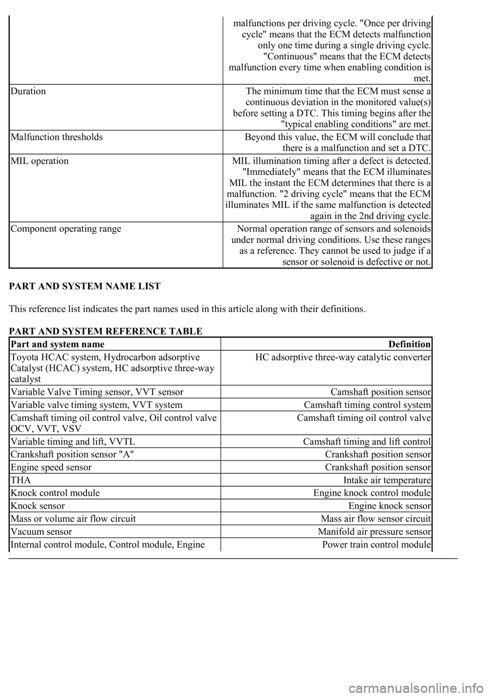
PART AND SYSTEM NAME LIST
This reference list indicates the part names used in this article along with their definitions.
PART AND SYSTEM REFERENCE TABLE
malfunctions per driving cycle. "Once per driving
cycle" means that the ECM detects malfunction
only one time during a single driving cycle.
"Continuous" means that the ECM detects
malfunction every time when enabling condition is
met.
DurationThe minimum time that the ECM must sense a
continuous deviation in the monitored value(s)
before setting a DTC. This timing begins after the
"typical enabling conditions" are met.
Malfunction thresholdsBeyond this value, the ECM will conclude that
there is a malfunction and set a DTC.
MIL operationMIL illumination timing after a defect is detected.
"Immediately" means that the ECM illuminates
MIL the instant the ECM determines that there is a
malfunction. "2 driving cycle" means that the ECM
illuminates MIL if the same malfunction is detected
again in the 2nd driving cycle.
Component operating rangeNormal operation range of sensors and solenoids
under normal driving conditions. Use these ranges
as a reference. They cannot be used to judge if a
sensor or solenoid is defective or not.
Part and system nameDefinition
Toyota HCAC system, Hydrocarbon adsorptive
Catalyst (HCAC) system, HC adsorptive three-way
catalystHC adsorptive three-way catalytic converter
Variable Valve Timing sensor, VVT sensorCamshaft position sensor
Variable valve timing system, VVT systemCamshaft timing control system
Camshaft timing oil control valve, Oil control valve
OCV, VVT, VSVCamshaft timing oil control valve
Variable timing and lift, VVTLCamshaft timing and lift control
Crankshaft position sensor "A"Crankshaft position sensor
Engine speed sensorCrankshaft position sensor
THAIntake air temperature
Knock control moduleEngine knock control module
Knock sensorEngine knock sensor
Mass or volume air flow circuitMass air flow sensor circuit
Vacuum sensorManifold air pressure sensor
Internal control module, Control module, Engine Power train control module
Page 2670 of 4500

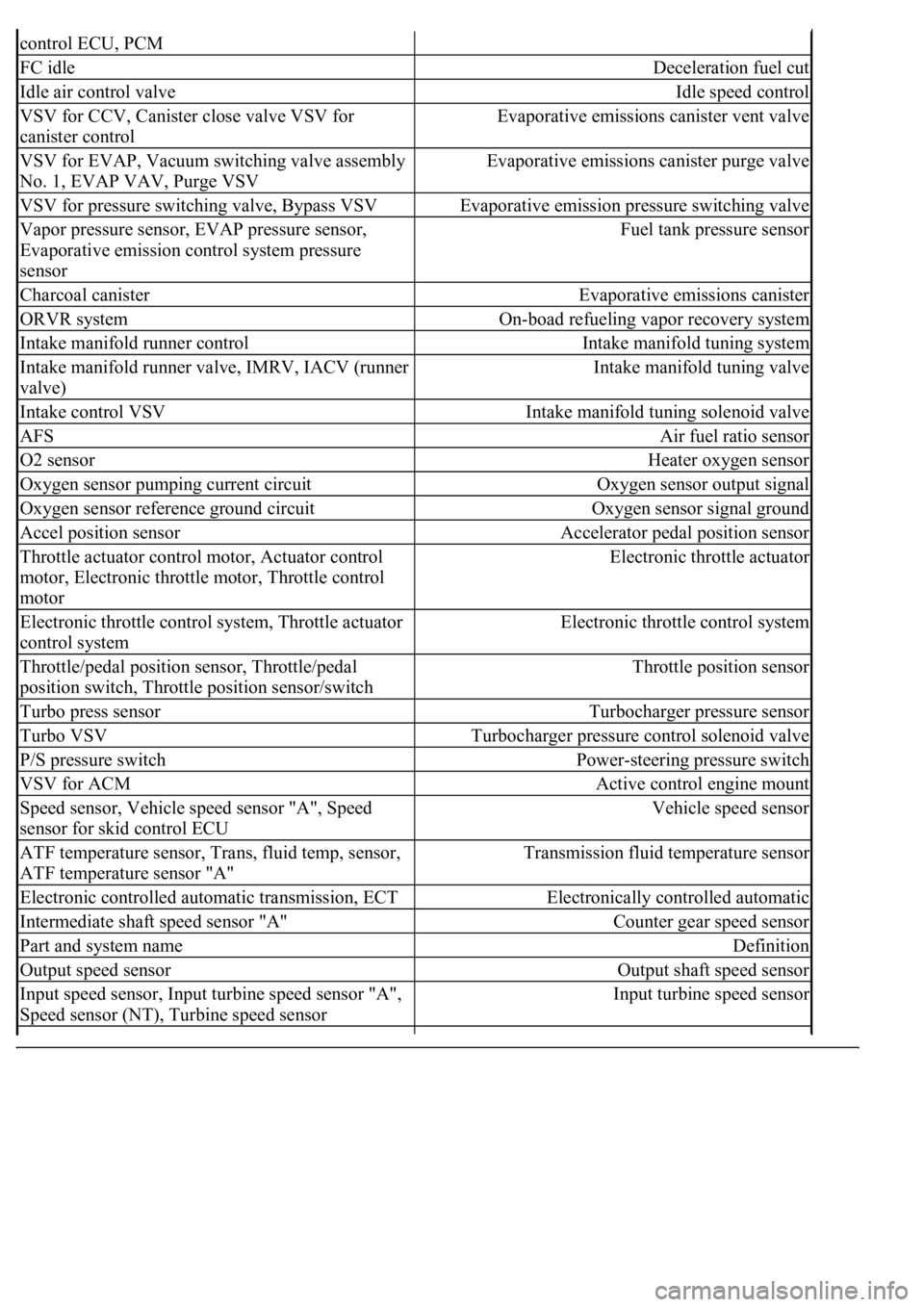
control ECU, PCM
FC idleDeceleration fuel cut
Idle air control valveIdle speed control
VSV for CCV, Canister close valve VSV for
canister controlEvaporative emissions canister vent valve
VSV for EVAP, Vacuum switching valve assembly
No. 1, EVAP VAV, Purge VSVEvaporative emissions canister purge valve
VSV for pressure switching valve, Bypass VSVEvaporative emission pressure switching valve
Vapor pressure sensor, EVAP pressure sensor,
Evaporative emission control system pressure
sensorFuel tank pressure sensor
Charcoal canisterEvaporative emissions canister
ORVR systemOn-boad refueling vapor recovery system
Intake manifold runner controlIntake manifold tuning system
Intake manifold runner valve, IMRV, IACV (runner
valve)Intake manifold tuning valve
Intake control VSVIntake manifold tuning solenoid valve
AFSAir fuel ratio sensor
O2 sensorHeater oxygen sensor
Oxygen sensor pumping current circuitOxygen sensor output signal
Oxygen sensor reference ground circuitOxygen sensor signal ground
Accel position sensorAccelerator pedal position sensor
Throttle actuator control motor, Actuator control
motor, Electronic throttle motor, Throttle control
motorElectronic throttle actuator
Electronic throttle control system, Throttle actuator
control systemElectronic throttle control system
Throttle/pedal position sensor, Throttle/pedal
position switch, Throttle position sensor/switchThrottle position sensor
Turbo press sensorTurbocharger pressure sensor
Turbo VSVTurbocharger pressure control solenoid valve
P/S pressure switchPower-steering pressure switch
VSV for ACMActive control engine mount
Speed sensor, Vehicle speed sensor "A", Speed
sensor for skid control ECUVehicle speed sensor
ATF temperature sensor, Trans, fluid temp, sensor,
ATF temperature sensor "A"Transmission fluid temperature sensor
Electronic controlled automatic transmission, ECTElectronically controlled automatic
Intermediate shaft speed sensor "A"Counter gear speed sensor
Part and system nameDefinition
Output speed sensorOutput shaft speed sensor
<002c00510053005800570003005600530048004800470003005600480051005600520055000f0003002c005100530058005700030057005800550045004c005100480003005600530048004800470003005600480051005600520055000300050024000500
0f0003[
Speed sensor (NT), Turbine speed sensorInput turbine speed sensor
Page 2671 of 4500
LOCATION
Fig. 1: Identifying Electronic Controlled Automatic Transmission Components Location (1 Of 2)
Courtesy of TOYOTA MOTOR SALES, U.S.A., INC.
PNP switch, NSWPark/neutral position switch
Pressure control solenoidTransmission pressure control solenoid
Shift solenoidTransmission shift solenoid valve
Transmission control switch, Shift lock control unitShift lock control module
Engine immobilizer system, Immobilizer systemVehicle anti-theft system
Page 2676 of 4500

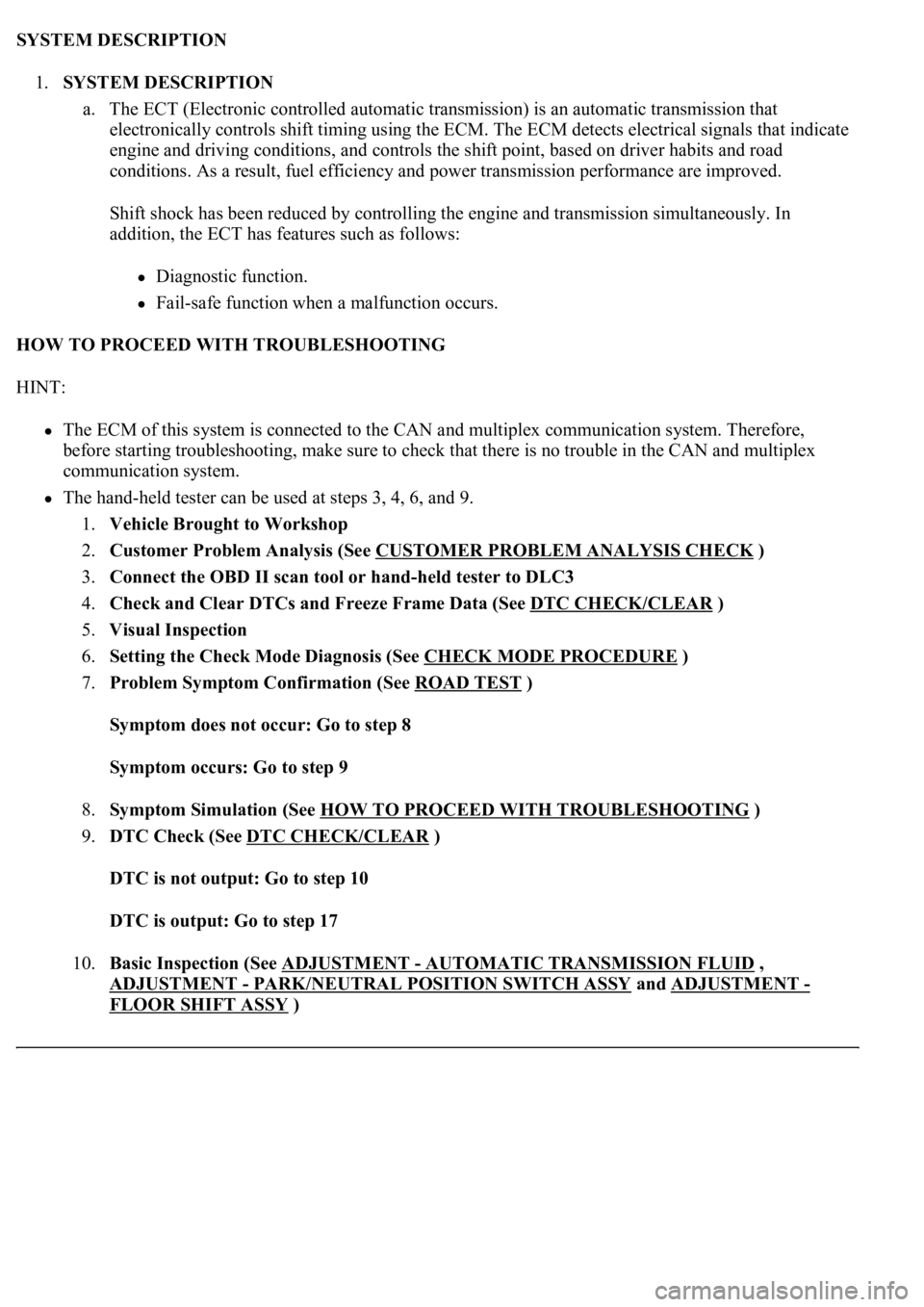
SYSTEM DESCRIPTION
1.SYSTEM DESCRIPTION
a. The ECT (Electronic controlled automatic transmission) is an automatic transmission that
electronically controls shift timing using the ECM. The ECM detects electrical signals that indicate
engine and driving conditions, and controls the shift point, based on driver habits and road
conditions. As a result, fuel efficiency and power transmission performance are improved.
<0036004b004c0049005700030056004b00520046004e0003004b00440056000300450048004800510003005500480047005800460048004700030045005c0003004600520051005700550052004f004f004c0051004a00030057004b004800030048005100
4a004c00510048000300440051004700030057005500440051[smission simultaneously. In
addition, the ECT has features such as follows:
Diagnostic function.
Fail-safe function when a malfunction occurs.
HOW TO PROCEED WITH TROUBLESHOOTING
HINT:
The ECM of this system is connected to the CAN and multiplex communication system. Therefore,
before starting troubleshooting, make sure to check that there is no trouble in the CAN and multiplex
communication system.
<0037004b00480003004b0044005100470010004b0048004f0047000300570048005600570048005500030046004400510003004500480003005800560048004700030044005700030056005700480053005600030016000f00030017000f00030019000f00
030044005100470003001c00110003[
1.Vehicle Brought to Workshop
2.Customer Problem Analysis (See CUSTOMER PROBLEM ANALYSIS CHECK
)
3.Connect the OBD II scan tool or hand-held tester to DLC3
4.Check and Clear DTCs and Freeze Frame Data (See DTC CHECK/CLEAR
)
5.Visual Inspection
6.Setting the Check Mode Diagnosis (See CHECK MODE PROCEDURE
)
7.Problem Symptom Confirmation (See ROAD TEST
)
Symptom does not occur: Go to step 8
Symptom occurs: Go to step 9
8.Symptom Simulation (See HOW TO PROCEED WITH TROUBLESHOOTING
)
9.DTC Check (See DTC CHECK/CLEAR
)
DTC is not output: Go to step 10
DTC is output: Go to step 17
10.Basic Inspection (See ADJUSTMENT
- AUTOMATIC TRANSMISSION FLUID ,
ADJUSTMENT
- PARK/NEUTRAL POSITION SWITCH ASSY and ADJUSTMENT -
FLOOR SHIFT ASSY
)
Page 2679 of 4500

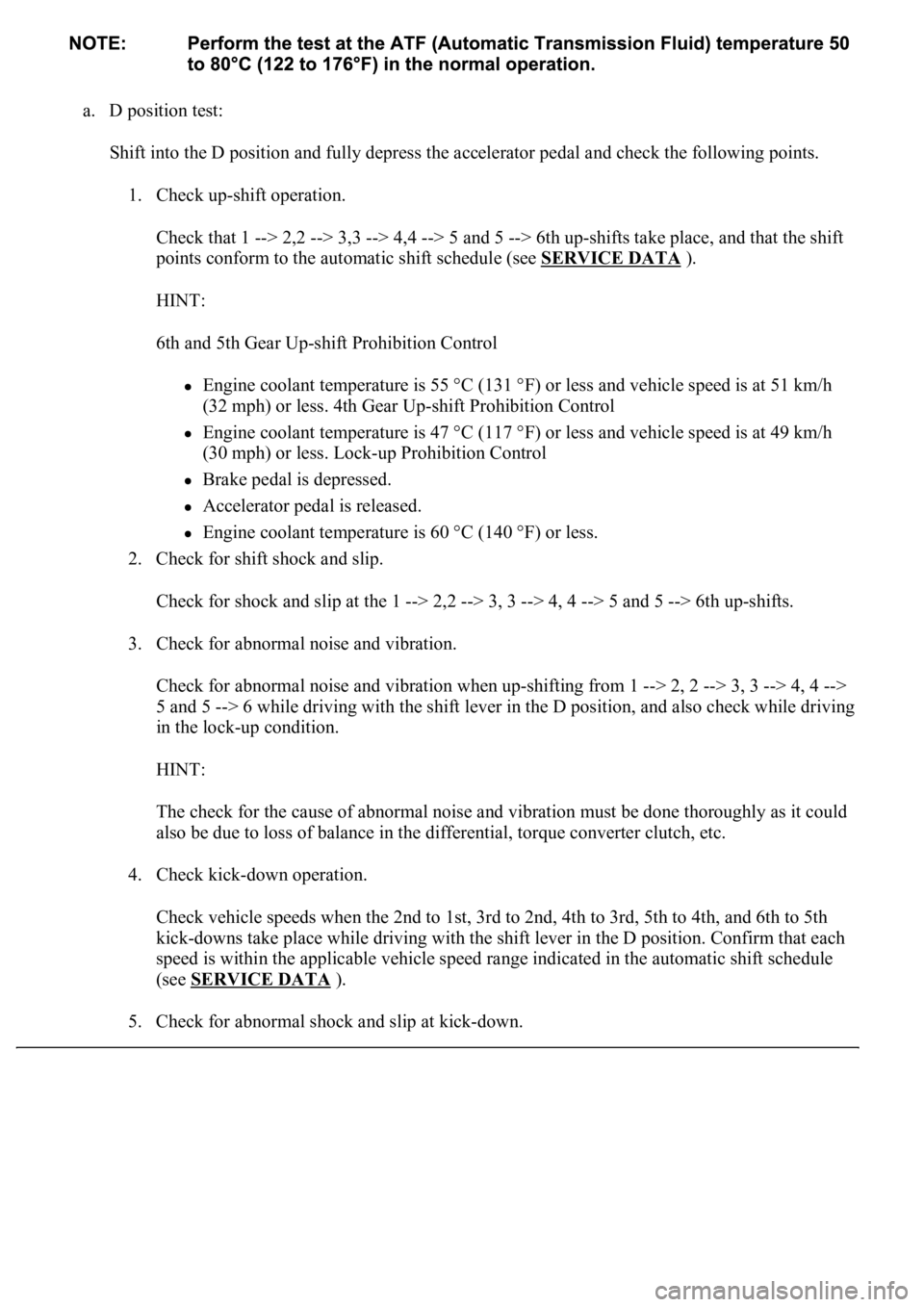
a. D position test:
Shift into the D position and fully depress the accelerator pedal and check the following points.
1. Check up-shift operation.
Check that 1 --> 2,2 --> 3,3 --> 4,4 --> 5 and 5 --> 6th up-shifts take place, and that the shift
points conform to the automatic shift schedule (see SERVICE DATA
).
HINT:
6th and 5th Gear Up-shift Prohibition Control
Engine coolant temperature is 55 °C (131 °F) or less and vehicle speed is at 51 km/h
(32 mph) or less. 4th Gear Up-shift Prohibition Control
Engine coolant temperature is 47 °C (117 °F) or less and vehicle speed is at 49 km/h
(30 mph) or less. Lock-up Prohibition Control
Brake pedal is depressed.
Accelerator pedal is released.
<00280051004a004c005100480003004600520052004f0044005100570003005700480050005300480055004400570058005500480003004c00560003001900130003008300260003000b001400170013000300830029000c0003005200550003004f004800
560056001100030003[
2. Check for shift shock and slip.
Check for shock and slip at the 1 --> 2,2 --> 3, 3 --> 4, 4 --> 5 and 5 --> 6th up-shifts.
3. Check for abnormal noise and vibration.
Check for abnormal noise and vibration when up-shifting from 1 --> 2, 2 --> 3, 3 --> 4, 4 -->
5 and 5 --> 6 while driving with the shift lever in the D position, and also check while driving
in the lock-up condition.
HINT:
The check for the cause of abnormal noise and vibration must be done thoroughly as it could
also be due to loss of balance in the differential, torque converter clutch, etc.
4. Check kick-down operation.
<0026004b00480046004e000300590048004b004c0046004f004800030056005300480048004700560003005a004b0048005100030057004b004800030015005100470003005700520003001400560057000f00030016005500470003005700520003001500
510047000f000300170057004b000300570052000300160055[d, 5th to 4th, and 6th to 5th
kick-downs take place while driving with the shift lever in the D position. Confirm that each
speed is within the applicable vehicle speed range indicated in the automatic shift schedule
(see SERVICE DATA
).
5. Check for abnormal shock and slip at kic
k-down.