2003 LEXUS LS430 engine
[x] Cancel search: enginePage 2628 of 4500
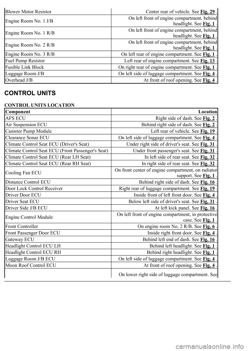
CONTROL UNITS LOCATION
Blower Motor ResistorCenter rear of vehicle. See Fig. 29 .
Engine Room No. 1 J/BOn left front of engine compartment, behind
headlight. See Fig. 1
.
Engine Room No. 1 R/BOn left front of engine compartment, behind
headlight. See Fig. 1
.
Engine Room No. 2 R/BOn left front of engine compartment, behind
headlight. See Fig. 1
.
Engine Room No. 3 R/BOn left rear of engine compartment. See Fig. 1 .
Fuel Pump ResistorLeft rear of engine compartment. See Fig. 13 .
Fusible Link BlockOn right rear of engine compartment. See Fig. 1 .
Luggage Room J/BOn left side of luggage compartment. See Fig. 4 .
Overhead J/BAt front of roof opening. See Fig. 4 .
ComponentLocation
AFS ECURight side of dash. See Fig. 2 .
Air Suspension ECUBehind right side of dash. See Fig. 2 .
Canister Pump ModuleLeft rear of vehicle. See Fig. 19 .
Clearance Sonar ECUOn left side of luggage compartment. See Fig. 4 .
Climate Control Seat ECU (Driver's Seat)Under right side of driver's seat. See Fig. 31 .
Climate Control Seat ECU (Front Passenger's Seat)Under front passenger's seat. See Fig. 31 .
Climate Control Seat ECU (Rear LH Seat)In left side of rear seat. See Fig. 32 .
Climate Control Seat ECU (Rear RH Seat)In right side of rear seat. See Fig. 32 .
Cooling Fan ECUOn front center of engine compartment, on radiator
support. See Fig. 1
.
Distance Control ECUBehind right side of dash. See Fig. 16 .
Door Lock Control ReceiverRight rear of luggage compartment. See Fig. 19 .
Driver Door ECUInside front of left front door. See Fig. 4 .
Driver Seat ECUBelow left side of driver's seat. See Fig. 31 .
Driver Side J/B ECUAt left kick panel. See Fig. 16 .
Engine Control ModuleOn left front of engine compartment, in protective
case. See Fig. 1
.
Front ControllerOn engine room No. 2 R/B. See Fig. 6 .
Front Passenger Door ECUInside right front door. See Fig. 4 .
Gateway ECUBehind left end of dash. See Fig. 16 .
Headlight Control ECU LHBehind left headlight. See Fig. 1 .
Headlight Control ECU RHBehind right headlight. See Fig. 1 .
Luggage Room J/B ECUOn left side of luggage compartment. See Fig. 4 .
Moon Roof Control ECUAt front of roof opening. See Fig. 4 .
On lower right side of luggage compartment. See
Page 2630 of 4500
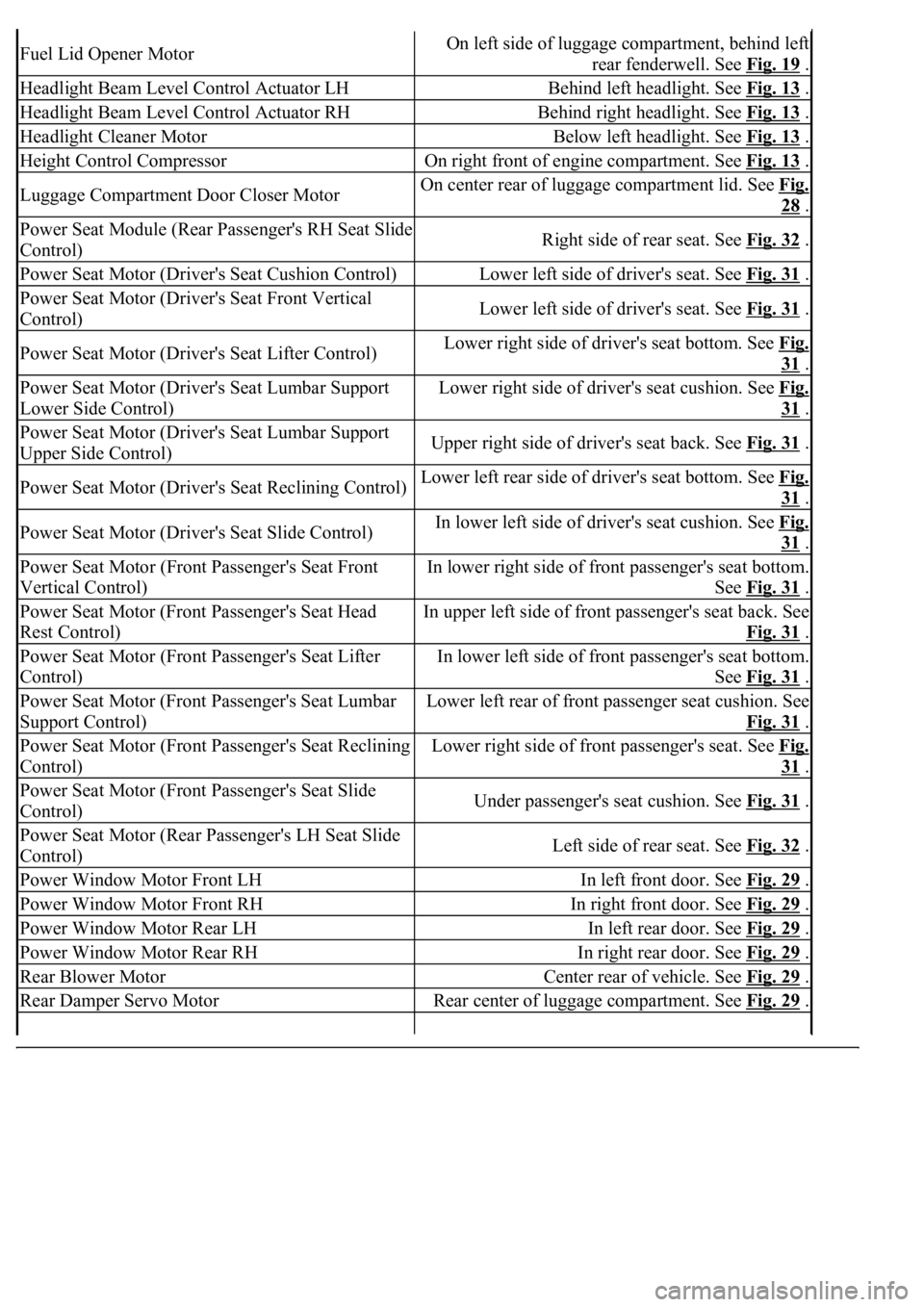
Fuel Lid Opener MotorOn left side of luggage compartment, behind left
rear fenderwell. See Fig. 19
.
Headlight Beam Level Control Actuator LHBehind left headlight. See Fig. 13 .
Headlight Beam Level Control Actuator RHBehind right headlight. See Fig. 13 .
Headlight Cleaner MotorBelow left headlight. See Fig. 13 .
Height Control CompressorOn right front of engine compartment. See Fig. 13 .
Luggage Compartment Door Closer MotorOn center rear of luggage compartment lid. See Fig.
28 .
Power Seat Module (Rear Passenger's RH Seat Slide
Control)Right side of rear seat. See Fig. 32 .
Power Seat Motor (Driver's Seat Cushion Control)Lower left side of driver's seat. See Fig. 31 .
Power Seat Motor (Driver's Seat Front Vertical
Control)Lower left side of driver's seat. See Fig. 31 .
Power Seat Motor (Driver's Seat Lifter Control)Lower right side of driver's seat bottom. See Fig.
31 .
Power Seat Motor (Driver's Seat Lumbar Support
Lower Side Control)Lower right side of driver's seat cushion. See Fig.
31 .
Power Seat Motor (Driver's Seat Lumbar Support
Upper Side Control)Upper right side of driver's seat back. See Fig. 31 .
Power Seat Motor (Driver's Seat Reclining Control)Lower left rear side of driver's seat bottom. See Fig.
31 .
Power Seat Motor (Driver's Seat Slide Control)In lower left side of driver's seat cushion. See Fig.
31 .
Power Seat Motor (Front Passenger's Seat Front
Vertical Control)In lower right side of front passenger's seat bottom.
See Fig. 31
.
Power Seat Motor (Front Passenger's Seat Head
Rest Control)In upper left side of front passenger's seat back. See
Fig. 31
.
Power Seat Motor (Front Passenger's Seat Lifter
Control)In lower left side of front passenger's seat bottom.
See Fig. 31
.
Power Seat Motor (Front Passenger's Seat Lumbar
Support Control)Lower left rear of front passenger seat cushion. See
Fig. 31
.
Power Seat Motor (Front Passenger's Seat Reclining
Control)Lower right side of front passenger's seat. See Fig.
31 .
Power Seat Motor (Front Passenger's Seat Slide
Control)Under passenger's seat cushion. See Fig. 31 .
Power Seat Motor (Rear Passenger's LH Seat Slide
Control)Left side of rear seat. See Fig. 32 .
Power Window Motor Front LHIn left front door. See Fig. 29 .
Power Window Motor Front RHIn right front door. See Fig. 29 .
Power Window Motor Rear LHIn left rear door. See Fig. 29 .
Power Window Motor Rear RHIn right rear door. See Fig. 29 .
Rear Blower MotorCenter rear of vehicle. See Fig. 29 .
Rear Damper Servo MotorRear center of luggage compartment. See Fig. 29 .
Page 2631 of 4500
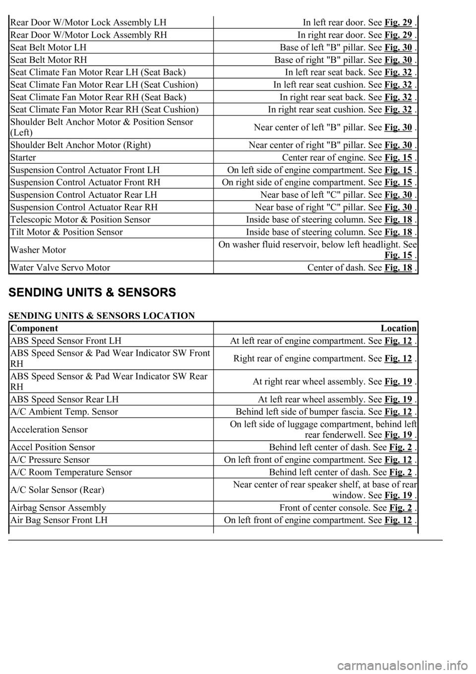
SENDING UNITS & SENSORS LOCATION
Rear Door W/Motor Lock Assembly LHIn left rear door. See Fig. 29 .
Rear Door W/Motor Lock Assembly RHIn right rear door. See Fig. 29 .
Seat Belt Motor LHBase of left "B" pillar. See Fig. 30 .
Seat Belt Motor RHBase of right "B" pillar. See Fig. 30 .
Seat Climate Fan Motor Rear LH (Seat Back)In left rear seat back. See Fig. 32 .
Seat Climate Fan Motor Rear LH (Seat Cushion)In left rear seat cushion. See Fig. 32 .
Seat Climate Fan Motor Rear RH (Seat Back)In right rear seat back. See Fig. 32 .
Seat Climate Fan Motor Rear RH (Seat Cushion)In right rear seat cushion. See Fig. 32 .
Shoulder Belt Anchor Motor & Position Sensor
(Left)Near center of left "B" pillar. See Fig. 30 .
Shoulder Belt Anchor Motor (Right)Near center of right "B" pillar. See Fig. 30 .
StarterCenter rear of engine. See Fig. 15 .
Suspension Control Actuator Front LHOn left side of engine compartment. See Fig. 15 .
Suspension Control Actuator Front RHOn right side of engine compartment. See Fig. 15 .
Suspension Control Actuator Rear LHNear base of left "C" pillar. See Fig. 30 .
Suspension Control Actuator Rear RHNear base of right "C" pillar. See Fig. 30 .
Telescopic Motor & Position SensorInside base of steering column. See Fig. 18 .
Tilt Motor & Position SensorInside base of steering column. See Fig. 18 .
Washer MotorOn washer fluid reservoir, below left headlight. See
Fig. 15
.
Water Valve Servo MotorCenter of dash. See Fig. 18 .
ComponentLocation
ABS Speed Sensor Front LHAt left rear of engine compartment. See Fig. 12 .
ABS Speed Sensor & Pad Wear Indicator SW Front
RHRight rear of engine compartment. See Fig. 12 .
ABS Speed Sensor & Pad Wear Indicator SW Rear
RHAt right rear wheel assembly. See Fig. 19 .
ABS Speed Sensor Rear LHAt left rear wheel assembly. See Fig. 19 .
A/C Ambient Temp. SensorBehind left side of bumper fascia. See Fig. 12 .
Acceleration SensorOn left side of luggage compartment, behind left
rear fenderwell. See Fig. 19
.
Accel Position SensorBehind left center of dash. See Fig. 2 .
A/C Pressure SensorOn left front of engine compartment. See Fig. 12 .
A/C Room Temperature SensorBehind left center of dash. See Fig. 2 .
A/C Solar Sensor (Rear)Near center of rear speaker shelf, at base of rear
window. See Fig. 19
.
Airbag Sensor AssemblyFront of center console. See Fig. 2 .
Air Bag Sensor Front LHOn left front of engine compartment. See Fig. 12 .
Page 2632 of 4500
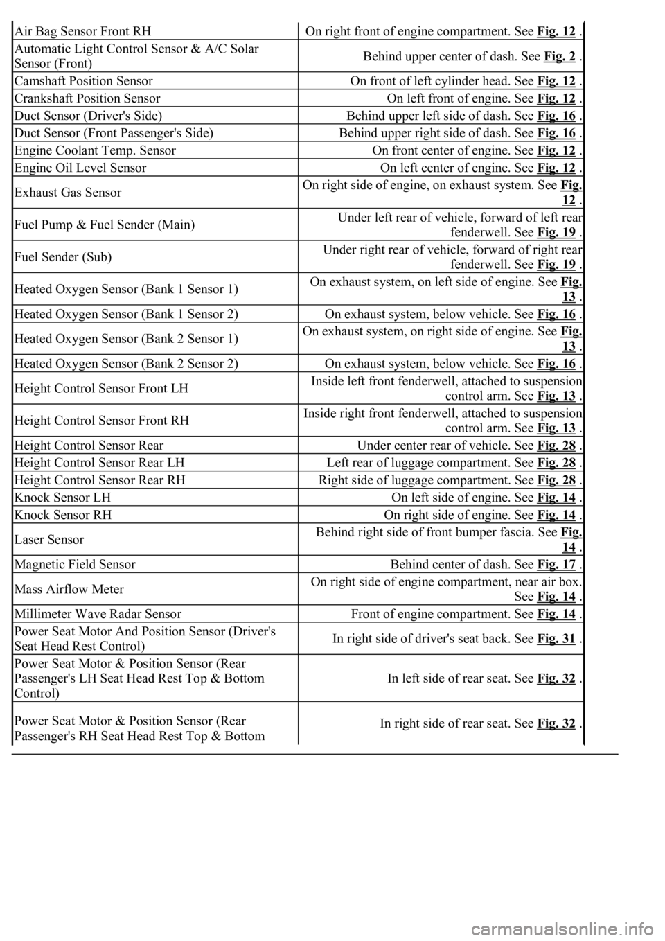
Air Bag Sensor Front RHOn right front of engine compartment. See Fig. 12 .
Automatic Light Control Sensor & A/C Solar
Sensor (Front)Behind upper center of dash. See Fig. 2 .
Camshaft Position SensorOn front of left cylinder head. See Fig. 12 .
Crankshaft Position SensorOn left front of engine. See Fig. 12 .
Duct Sensor (Driver's Side)Behind upper left side of dash. See Fig. 16 .
Duct Sensor (Front Passenger's Side)Behind upper right side of dash. See Fig. 16 .
Engine Coolant Temp. SensorOn front center of engine. See Fig. 12 .
Engine Oil Level SensorOn left center of engine. See Fig. 12 .
Exhaust Gas SensorOn right side of engine, on exhaust system. See Fig.
12 .
Fuel Pump & Fuel Sender (Main)Under left rear of vehicle, forward of left rear
fenderwell. See Fig. 19
.
Fuel Sender (Sub)Under right rear of vehicle, forward of right rear
fenderwell. See Fig. 19
.
Heated Oxygen Sensor (Bank 1 Sensor 1)On exhaust system, on left side of engine. See Fig.
13 .
Heated Oxygen Sensor (Bank 1 Sensor 2)On exhaust system, below vehicle. See Fig. 16 .
Heated Oxygen Sensor (Bank 2 Sensor 1)On exhaust system, on right side of engine. See Fig.
13 .
Heated Oxygen Sensor (Bank 2 Sensor 2)On exhaust system, below vehicle. See Fig. 16 .
Height Control Sensor Front LHInside left front fenderwell, attached to suspension
control arm. See Fig. 13
.
Height Control Sensor Front RHInside right front fenderwell, attached to suspension
control arm. See Fig. 13
.
Height Control Sensor RearUnder center rear of vehicle. See Fig. 28 .
Height Control Sensor Rear LHLeft rear of luggage compartment. See Fig. 28 .
Height Control Sensor Rear RHRight side of luggage compartment. See Fig. 28 .
Knock Sensor LHOn left side of engine. See Fig. 14 .
Knock Sensor RHOn right side of engine. See Fig. 14 .
Laser SensorBehind right side of front bumper fascia. See Fig.
14 .
Magnetic Field SensorBehind center of dash. See Fig. 17 .
Mass Airflow MeterOn right side of engine compartment, near air box.
See Fig. 14
.
Millimeter Wave Radar SensorFront of engine compartment. See Fig. 14 .
Power Seat Motor And Position Sensor (Driver's
Seat Head Rest Control)In right side of driver's seat back. See Fig. 31 .
Power Seat Motor & Position Sensor (Rear
Passenger's LH Seat Head Rest Top & Bottom
Control)
In left side of rear seat. See Fig. 32 .
Power Seat Motor & Position Sensor (Rear
Passenger's RH Seat Head Rest Top & Bottom In right side of rear seat. See Fig. 32 .
Page 2633 of 4500
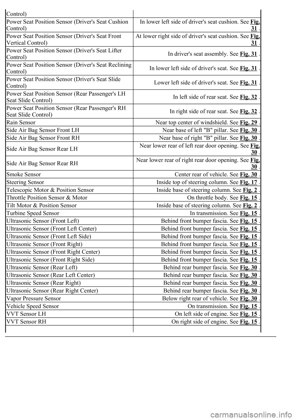
Control)
Power Seat Position Sensor (Driver's Seat Cushion
Control)In lower left side of driver's seat cushion. See Fig.
31 .
Power Seat Position Sensor (Driver's Seat Front
Vertical Control)At lower right side of driver's seat cushion. See Fig.
31 .
Power Seat Position Sensor (Driver's Seat Lifter
Control)In driver's seat assembly. See Fig. 31 .
Power Seat Position Sensor (Driver's Seat Reclining
Control)In lower left side of driver's seat. See Fig. 31 .
Power Seat Position Sensor (Driver's Seat Slide
Control)Lower left side of driver's seat. See Fig. 31 .
Power Seat Position Sensor (Rear Passenger's LH
Seat Slide Control)In left side of rear seat. See Fig. 32 .
Power Seat Position Sensor (Rear Passenger's RH
Seat Slide Control)In right side of rear seat. See Fig. 32 .
Rain SensorNear top center of windshield. See Fig. 29 .
Side Air Bag Sensor Front LHNear base of left "B" pillar. See Fig. 30 .
Side Air Bag Sensor Front RHNear base of right "B" pillar. See Fig. 30 .
Side Air Bag Sensor Rear LHNear lower rear of left rear door opening. See Fig.
30 .
Side Air Bag Sensor Rear RHNear lower rear of right rear door opening. See Fig.
30 .
Smoke SensorCenter rear of vehicle. See Fig. 30 .
Steering SensorInside top of steering column. See Fig. 17 .
Telescopic Motor & Position SensorInside base of steering column. See Fig. 2 .
Throttle Position Sensor & MotorOn throttle body. See Fig. 15 .
Tilt Motor & Position SensorInside base of steering column. See Fig. 2 .
Turbine Speed SensorIn transmission. See Fig. 15 .
Ultrasonic Sensor (Front Left)Behind front bumper fascia. See Fig. 15 .
Ultrasonic Sensor (Front Left Center)Behind front bumper fascia. See Fig. 15 .
Ultrasonic Sensor (Front Left Side)Behind front bumper fascia. See Fig. 15 .
Ultrasonic Sensor (Front Right)Behind front bumper fascia. See Fig. 15 .
Ultrasonic Sensor (Front Right Center)Behind front bumper fascia. See Fig. 15 .
Ultrasonic Sensor (Front Right Side)Behind front bumper fascia. See Fig. 15 .
Ultrasonic Sensor (Rear Left)Behind rear bumper fascia. See Fig. 30 .
Ultrasonic Sensor (Rear Left Center)Behind rear bumper fascia. See Fig. 30 .
Ultrasonic Sensor (Rear Right)Behind rear bumper fascia. See Fig. 30 .
Ultrasonic Sensor (Rear Right Center)Behind rear bumper fascia. See Fig. 30 .
Vapor Pressure SensorBelow right rear of vehicle. See Fig. 30 .
Vehicle Speed SensorOn transmission. See Fig. 15 .
VVT Sensor LHOn left side of engine. See Fig. 15 .
VVT Sensor RHOn right side of engine. See Fig. 15 .
Page 2634 of 4500
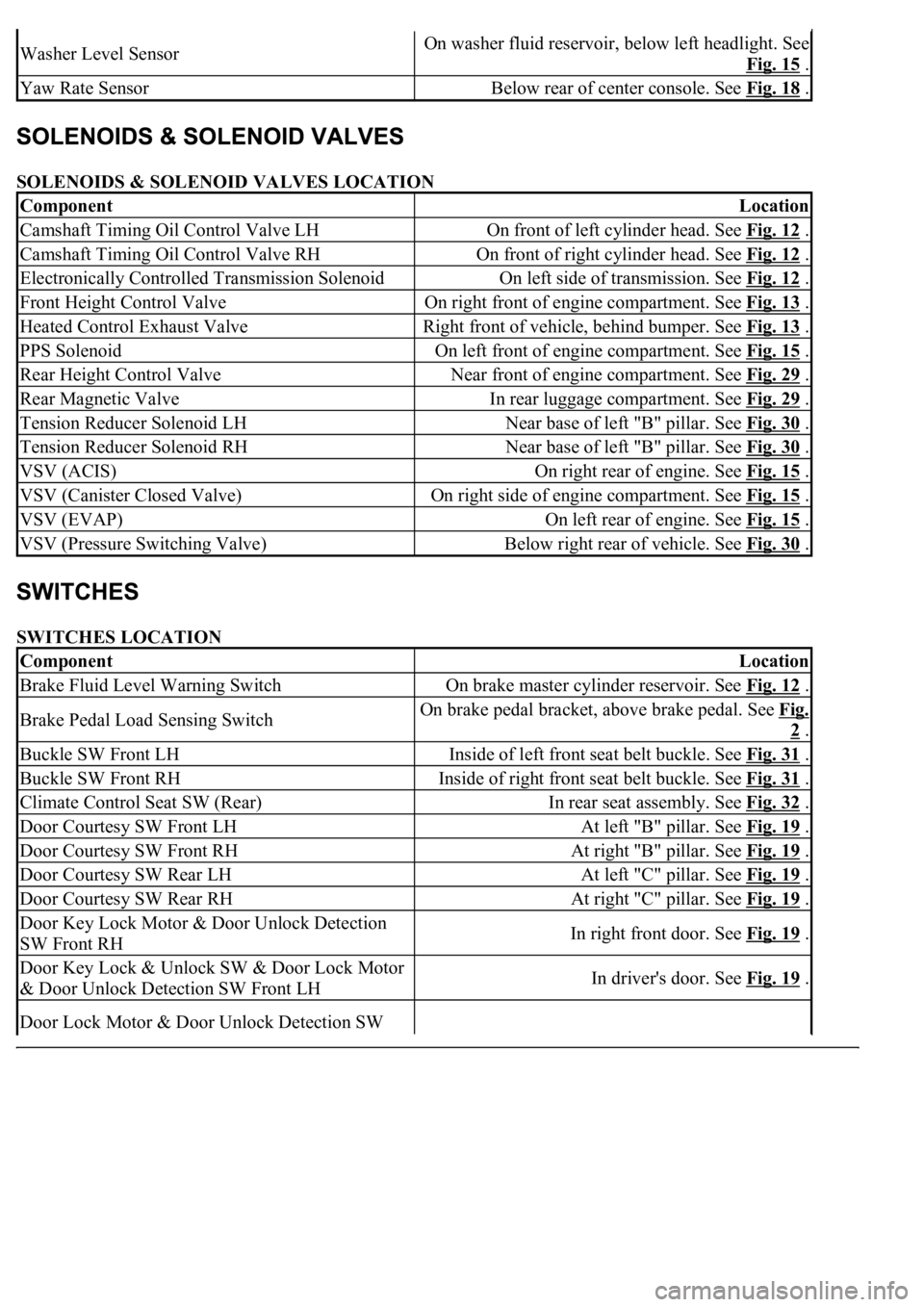
SOLENOIDS & SOLENOID VALVES LOCATION
SWITCHES LOCATION
Washer Level SensorOn washer fluid reservoir, below left headlight. See
Fig. 15
.
Yaw Rate SensorBelow rear of center console. See Fig. 18 .
ComponentLocation
Camshaft Timing Oil Control Valve LHOn front of left cylinder head. See Fig. 12 .
Camshaft Timing Oil Control Valve RHOn front of right cylinder head. See Fig. 12 .
Electronically Controlled Transmission SolenoidOn left side of transmission. See Fig. 12 .
Front Height Control ValveOn right front of engine compartment. See Fig. 13 .
Heated Control Exhaust ValveRight front of vehicle, behind bumper. See Fig. 13 .
PPS SolenoidOn left front of engine compartment. See Fig. 15 .
Rear Height Control ValveNear front of engine compartment. See Fig. 29 .
Rear Magnetic ValveIn rear luggage compartment. See Fig. 29 .
Tension Reducer Solenoid LHNear base of left "B" pillar. See Fig. 30 .
Tension Reducer Solenoid RHNear base of left "B" pillar. See Fig. 30 .
VSV (ACIS)On right rear of engine. See Fig. 15 .
VSV (Canister Closed Valve)On right side of engine compartment. See Fig. 15 .
VSV (EVAP)On left rear of engine. See Fig. 15 .
VSV (Pressure Switching Valve)Below right rear of vehicle. See Fig. 30 .
ComponentLocation
Brake Fluid Level Warning SwitchOn brake master cylinder reservoir. See Fig. 12 .
Brake Pedal Load Sensing SwitchOn brake pedal bracket, above brake pedal. See Fig.
2 .
Buckle SW Front LHInside of left front seat belt buckle. See Fig. 31 .
Buckle SW Front RHInside of right front seat belt buckle. See Fig. 31 .
Climate Control Seat SW (Rear)In rear seat assembly. See Fig. 32 .
Door Courtesy SW Front LHAt left "B" pillar. See Fig. 19 .
Door Courtesy SW Front RHAt right "B" pillar. See Fig. 19 .
Door Courtesy SW Rear LHAt left "C" pillar. See Fig. 19 .
Door Courtesy SW Rear RHAt right "C" pillar. See Fig. 19 .
Door Key Lock Motor & Door Unlock Detection
SW Front RHIn right front door. See Fig. 19 .
Door Key Lock & Unlock SW & Door Lock Motor
& Door Unlock Detection SW Front LHIn driver's door. See Fig. 19 .
Door Lock Motor & Door Unlock Detection SW
Page 2635 of 4500
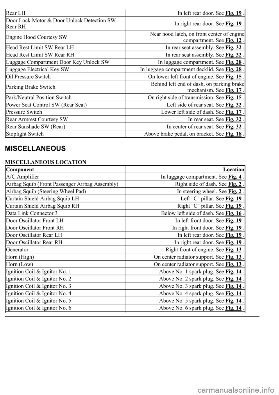
MISCELLANEOUS LOCATION
Rear LHIn left rear door. See Fig. 19 .
Door Lock Motor & Door Unlock Detection SW
Rear RHIn right rear door. See Fig. 19 .
Engine Hood Courtesy SWNear hood latch, on front center of engine
compartment. See Fig. 12
.
Head Rest Limit SW Rear LHIn rear seat assembly. See Fig. 32 .
Head Rest Limit SW Rear RHIn rear seat assembly. See Fig. 32 .
Luggage Compartment Door Key Unlock SWIn luggage compartment. See Fig. 28 .
Luggage Electrical Key SWIn luggage compartment decklid. See Fig. 28 .
Oil Pressure SwitchOn lower left front of engine. See Fig. 15 .
Parking Brake SwitchBehind left end of dash, on parking brake
mechanism. See Fig. 17
.
Park/Neutral Position SwitchOn right side of transmission. See Fig. 15 .
Power Seat Control SW (Rear Seat)Left side of rear seat. See Fig. 32 .
Pressure SwitchLower left side of dash. See Fig. 17 .
Rear Armrest Courtesy SWIn rear seat. See Fig. 32 .
Rear Sunshade SW (Rear)In center of rear seat. See Fig. 32 .
Stoplight SwitchAbove brake pedal, on bracket. See Fig. 18 .
ComponentLocation
A/C AmplifierIn luggage compartment. See Fig. 4 .
Airbag Squib (Front Passenger Airbag Assembly)Right side of dash. See Fig. 2 .
Airbag Squib (Steering Wheel Pad)In steering wheel. See Fig. 2 .
Curtain Shield Airbag Squib LHLeft "C" pillar. See Fig. 19 .
Curtain Shield Airbag Squib RHRight "C" pillar. See Fig. 19 .
Data Link Connector 3Below left side of dash. See Fig. 16 .
Door Oscillator Front LHIn left front door. See Fig. 19 .
Door Oscillator Front RHIn right front door. See Fig. 19 .
Door Oscillator Rear LHIn left rear door. See Fig. 19 .
Door Oscillator Rear RHIn right rear door. See Fig. 19 .
GeneratorRight front of engine. See Fig. 13 .
Horn (High)On center radiator support. See Fig. 13 .
Horn (Low)On center radiator support. See Fig. 13 .
Ignition Coil & Ignitor No. 1Above No. 1 spark plug. See Fig. 14 .
Ignition Coil & Ignitor No. 2Above No. 2 spark plug. See Fig. 14 .
Ignition Coil & Ignitor No. 3Above No. 3 spark plug. See Fig. 14 .
Ignition Coil & Ignitor No. 4Above No. 4 spark plug. See Fig. 14 .
Ignition Coil & Ignitor No. 5Above No. 5 spark plug. See Fig. 14 .
Ignition Coil & Ignitor No. 6Above No. 6 spark plug. See Fig. 14 .
Page 2636 of 4500
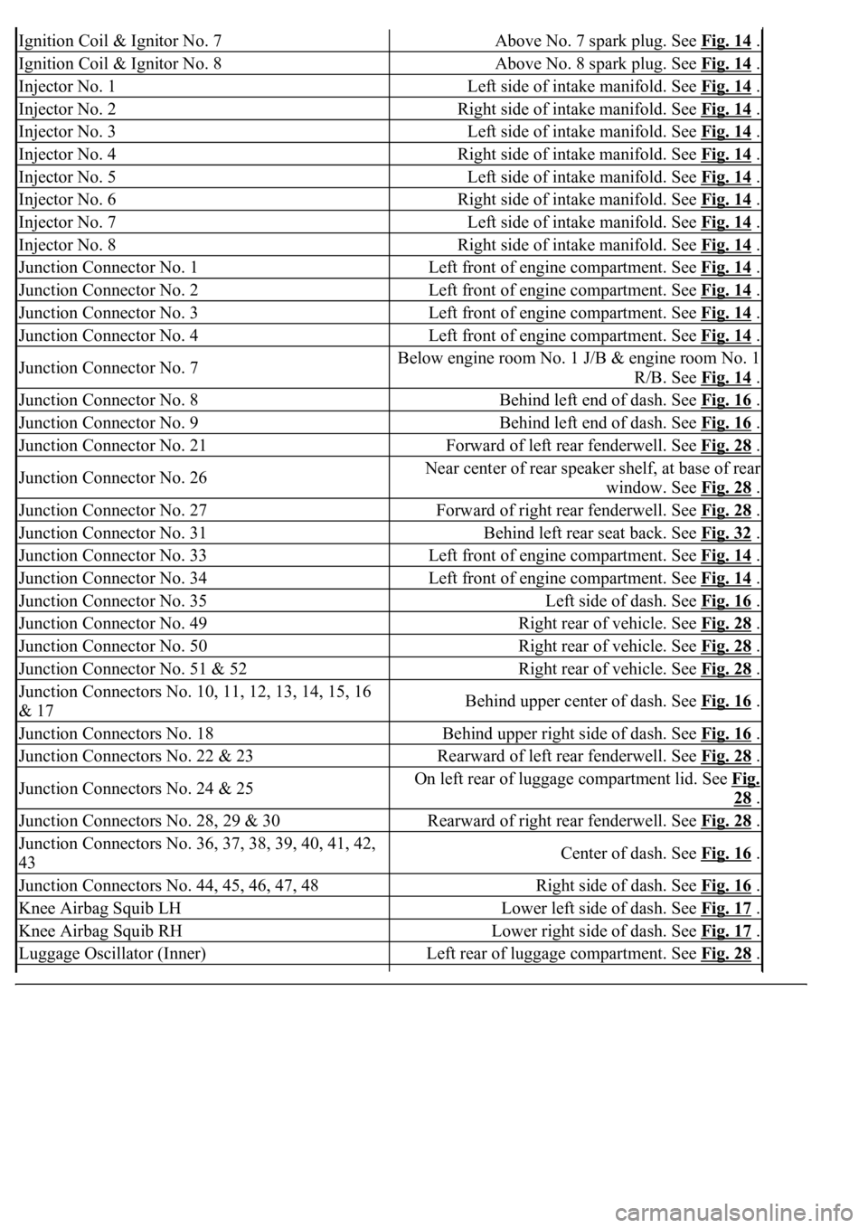
Ignition Coil & Ignitor No. 7Above No. 7 spark plug. See Fig. 14 .
Ignition Coil & Ignitor No. 8Above No. 8 spark plug. See Fig. 14 .
Injector No. 1Left side of intake manifold. See Fig. 14 .
Injector No. 2Right side of intake manifold. See Fig. 14 .
Injector No. 3Left side of intake manifold. See Fig. 14 .
Injector No. 4Right side of intake manifold. See Fig. 14 .
Injector No. 5Left side of intake manifold. See Fig. 14 .
Injector No. 6Right side of intake manifold. See Fig. 14 .
Injector No. 7Left side of intake manifold. See Fig. 14 .
Injector No. 8Right side of intake manifold. See Fig. 14 .
Junction Connector No. 1Left front of engine compartment. See Fig. 14 .
Junction Connector No. 2Left front of engine compartment. See Fig. 14 .
Junction Connector No. 3Left front of engine compartment. See Fig. 14 .
Junction Connector No. 4Left front of engine compartment. See Fig. 14 .
Junction Connector No. 7Below engine room No. 1 J/B & engine room No. 1
R/B. See Fig. 14
.
Junction Connector No. 8Behind left end of dash. See Fig. 16 .
Junction Connector No. 9Behind left end of dash. See Fig. 16 .
Junction Connector No. 21Forward of left rear fenderwell. See Fig. 28 .
Junction Connector No. 26Near center of rear speaker shelf, at base of rear
window. See Fig. 28
.
Junction Connector No. 27Forward of right rear fenderwell. See Fig. 28 .
Junction Connector No. 31Behind left rear seat back. See Fig. 32 .
Junction Connector No. 33Left front of engine compartment. See Fig. 14 .
Junction Connector No. 34Left front of engine compartment. See Fig. 14 .
Junction Connector No. 35Left side of dash. See Fig. 16 .
Junction Connector No. 49Right rear of vehicle. See Fig. 28 .
Junction Connector No. 50Right rear of vehicle. See Fig. 28 .
Junction Connector No. 51 & 52Right rear of vehicle. See Fig. 28 .
<002d0058005100460057004c00520051000300260052005100510048004600570052005500560003003100520011000300140013000f000300140014000f000300140015000f000300140016000f000300140017000f000300140018000f00030014001900
03[
& 17Behind upper center of dash. See Fig. 16 .
Junction Connectors No. 18Behind upper right side of dash. See Fig. 16 .
Junction Connectors No. 22 & 23Rearward of left rear fenderwell. See Fig. 28 .
Junction Connectors No. 24 & 25On left rear of luggage compartment lid. See Fig.
28 .
Junction Connectors No. 28, 29 & 30Rearward of right rear fenderwell. See Fig. 28 .
<002d0058005100460057004c00520051000300260052005100510048004600570052005500560003003100520011000300160019000f00030016001a000f00030016001b000f00030016001c000f000300170013000f000300170014000f00030017001500
0f0003[
43Center of dash. See Fig. 16 .
Junction Connectors No. 44, 45, 46, 47, 48Right side of dash. See Fig. 16 .
Knee Airbag Squib LHLower left side of dash. See Fig. 17 .
Knee Airbag Squib RHLower right side of dash. See Fig. 17 .
Luggage Oscillator (Inner)Left rear of luggage compartment. See Fig. 28 .