Page 2708 of 4500
Fig. 30: Identifying Waveform 5
Courtesy of TOYOTA MOTOR SALES, U.S.A., INC.
Reference:
WAVEFORM 5 REFERENCE TABLE
Waveform 6
TerminalNT+ - NT-
Tool setting1V/DIV, 2ms/DIV
Vehicle conditionEngine idle speed (P or N position)
Page 2710 of 4500
2. The powertrain control components (which affect vehicle emissions)
3. The computer.
In addition, the applicable Diagnostic Trouble Codes (DTCs) prescribed by SAE J2012 are recorded in the
ECM memory. If the malfunction does not reoccur in 3 consecutive trips, the MIL turns off automatically but
the DTCs remain recorded in the ECM memory.
Fig. 32: Identifying Malfunction Indicator Lamp
Courtesy of TOYOTA MOTOR SALES, U.S.A., INC.
To check DTCs, connect the scan tool to the Data Link Connector 3 (DLC3) of the vehicle. The scan tool
displays DTCs, the freeze frame data and a variety of the engine data.
Page 2712 of 4500
Fig. 34: Identifying DLC3 Terminals
Courtesy of TOYOTA MOTOR SALES, U.S.A., INC.
FREEZE FRAME DATA
Freeze frame data records the engine conditions (fuel system, calculated load, engine coolant temperature, fuel
trim, engine speed, vehicle speed, etc.) when a malfunction is detected. When troubleshooting, freeze frame
data can help determine if the vehicle was running or stopped, if the engine was warmed up or not, if the air/fuel
ratio was Lean or Rich, and other data from the time the malfunction occurred.
The hand-held tester records freeze frame data in five different instances: 1) 3 times before the DTC is set, 2)
once when the DTC is set, and 3) once after the DTC is set. These data can be used to simulate the vehicle's
condition around the time when the malfunction occurred. The data may help find the cause of the malfunction,
or
judge if the DTC is being caused by a temporary malfunction or not.
Page 2715 of 4500

CHECK BATTERY VOLTAGE
Battery voltage: 11 to 14 V
If voltage is below 11 V, replace the battery before proceeding.
CHECK MIL
a. Check that the MIL illuminates when turning the ignition switch ON.
If the MIL does not illuminate, there is a problem in the MIL circuit (refer to MIL CIRCUIT
)
b. When the engine is started, the MIL should turn off.
ALL READINESS
For this vehicle, using the hand-held tester allows readiness codes corresponding to all DTCs to be read. When
diagnosis (normal or malfunctioning) has been complete, readiness codes are set. Enter the following menus:
ENHANCED OBD II/ MONITOR STATUS on the hand-held tester.
DTC CHECK/CLEAR
1.CHECK DTC
DTCs which are stored in the ECM can be displayed with the hand-held tester or generic OBD II scan-
tool.
These scan tools can display pending DTCs and current DTCs. Some DTC aren't stored if the ECM
doesn't detect a malfunction during consecutive driving. However, the detected malfunction during once
driving is stored as pending DTC.
1. Connect the hand-held tester to the Controller Area Network Vehicle Interface Module (CAN
VIM). Then connect the CAN VIM to the Data Link Connector 3 (DLC3).
2. Turn the ignition switch ON.
3. Enter the following menus: DIAGNOSIS/ ENHANCED OBD II/ DTC INFO/ CURRENT CODES
(or PENDING CODE).
4. Confirm the DTCs and freeze frame data and then write them down.
5. See DIAGNOSTIC TROUBLE CODE CHART
to confirm the details of the DTCs.
CAN bus linehigher
Page 2718 of 4500
f. Change the ECM to check mode. Make sure the MIL flashes as shown in the illustration.
g. Start the engine. The MIL should turn off after the engine starts.
h. Perform "MONITOR DRIVE PATTERN" for the ECT test (see MONITOR DRIVE PATTERN
).
(Or, simulate the conditions of the malfunction described by the customer).
i. After simulating the malfunction conditions, use the hand-held tester diagnosis selector to check the DTC
and freeze frame data.
Fig. 39: Identifying MIL Blinking Pattern
Courtesy of TOYOTA MOTOR SALES, U.S.A., INC.
FAIL-SAFE CHART
1.FAIL-SAFE
Page 2719 of 4500

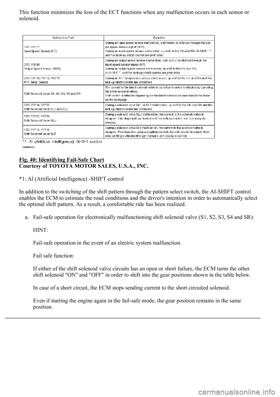
This function minimizes the loss of the ECT functions when any malfunction occurs in each sensor or
solenoid.
Fig. 40: Identifying Fail
-Safe Chart
Courtesy of TOYOTA MOTOR SALES, U.S.A., INC.
*1: Al (Artificial Intelligence) -SHIFT control
In addition to the switching of the shift pattern through the pattern select switch, the AI-SHIFT control
enables the ECM to estimate the road conditions and the driver's intention in order to automatically select
the optimal shift pattern. As a result, a comfortable ride has been realized.
a. Fail-safe operation for electronically malfunctioning shift solenoid valve (S1, S2, S3, S4 and SR):
HINT:
Fail-safe operation in the event of an electric system malfunction.
Fail safe function:
If either of the shift solenoid valve circuits has an open or short failure, the ECM turns the other
shift solenoid "ON" and "OFF" in order to shift into the gear positions shown in the table below.
In case of a short circuit, the ECM stops sending current to the short circuited solenoid.
Even if starting the engine again in the fail-safe mode, the gear position remains in the same
position.
Page 2723 of 4500
a. Warm up the engine.
b. Turn the ignition switch off.
c. Connect the hand-held tester together with the CAN VIM (controller area network vehicle interface
module) to the DLC3.
d. Turn the ignition switch to the ON position.
e. Push the "ON" button of the hand-held tester.
f. Select the item "DIAGNOSIS/ENHANCED OBD II/DATA LIST".
g. According to the display on tester, read the "DATA LIST".
Fig. 44: Identifying Data List Reference (1 Of 2)
Courtesy of TOYOTA MOTOR SALES, U.S.A., INC.
Page 2724 of 4500
Fig. 45: Identifying Data List Reference (2 Of 2)
Courtesy of TOYOTA MOTOR SALES, U.S.A., INC.
2.ACTIVE TEST
HINT:
Performing the ACTIVE TEST using the hand-held tester allows the relay, VSV, actuator and so on to
operate without parts removal. Performing the ACTIVE TEST as the first step of troubleshooting is one
method to shorten labor time.
It is possible to display the DATA LIST during the ACTIVE TEST.
a. Warm up the engine.
b. Turn the ignition switch off.
c. Connect the hand-held tester together with the CAN VIM (controller area network vehicle interface
module) to the DLC3.
d. Turn the ignition switch to the ON position.
e. Push the "ON" button of the hand-held tester.
f. Select the item "DIAGNOSIS/ENHANCED OBD II/ACTIVE TEST".
g. According to the display on tester, perform the "ACTIVE TEST".