Page 2729 of 4500
CIRCUIT DESCRIPTION
The park/neutral position switch detects the shift lever position and sends signals to the ECM.
Fig. 49: DTC Reference Chart
Courtesy of TOYOTA MOTOR SALES, U.S.A., INC.
MONITOR DESCRIPTION
These DTCs indicate a problem with the park/neutral position switch and the wire harness in the park/neutral
position switch circuit.
The park/neutral position switch detects the shift lever position and sends signals to the ECM.
For security, the park/neutral position switch detects the shift lever position so that engine can be started only
when the vehicle is in P or N shift position.
When the park/neutral position switch sends more than one signal at a time from switch positions P, R, N or D,
the ECM interprets this as a fault in the switch. The ECM will turn on the MIL and store the DTC.
MONITOR STRATEGY
P0705:
MONITOR STRATEGY TABLE - P0705
Related DTCsP0705: Park/neutral position switch/Verify switch
input
Page 2730 of 4500
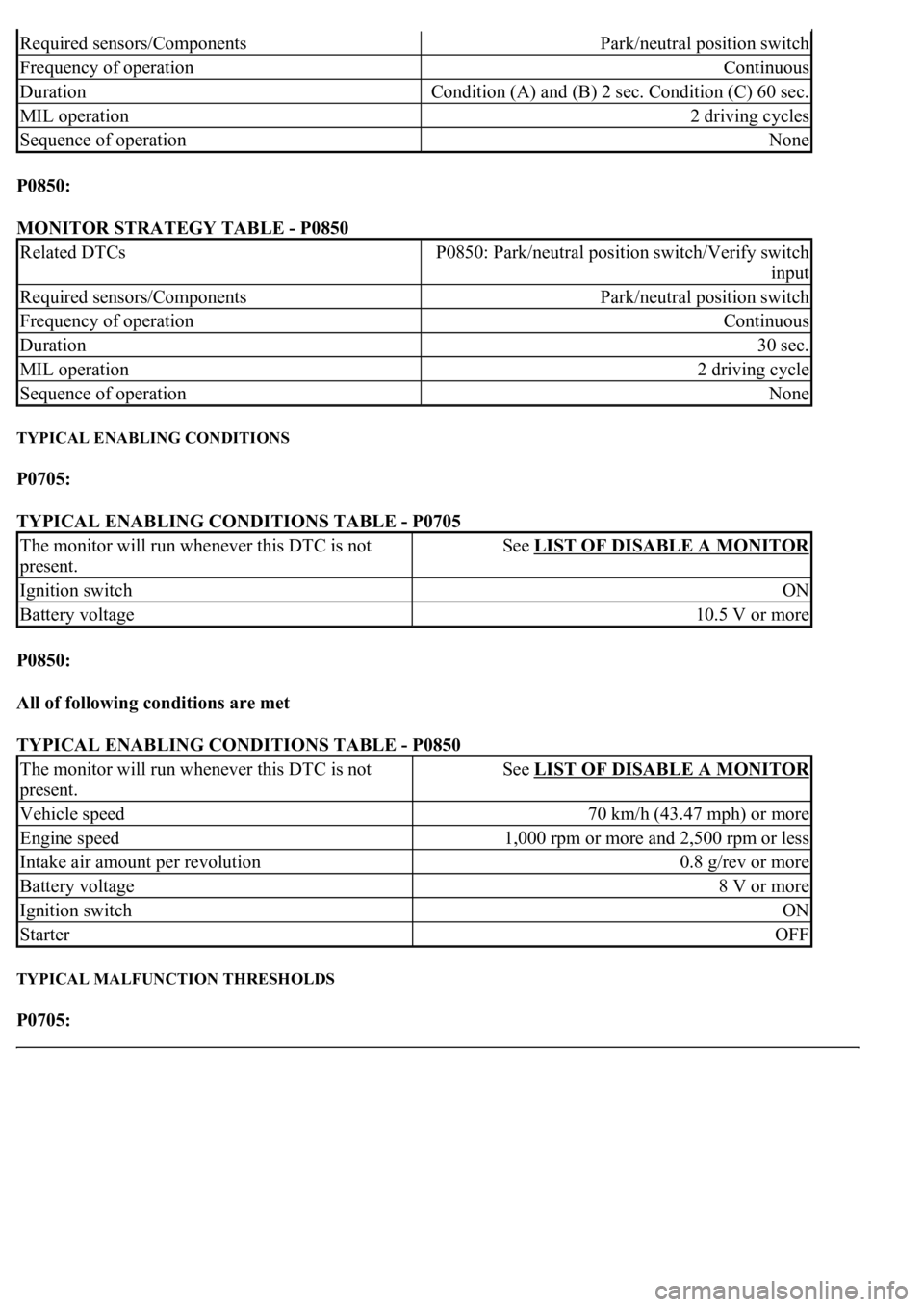
P0850:
MONITOR STRATEGY TABLE - P0850
TYPICAL ENABLING CONDITIONS
P0705:
TYPICAL ENABLING CONDITIONS TABLE - P0705
P0850:
All of following conditions are met
TYPICAL ENABLING CONDITIONS TABLE - P0850
TYPICAL MALFUNCTION THRESHOLDS
P0705:
Required sensors/ComponentsPark/neutral position switch
Frequency of operationContinuous
DurationCondition (A) and (B) 2 sec. Condition (C) 60 sec.
MIL operation2 driving cycles
Sequence of operationNone
Related DTCsP0850: Park/neutral position switch/Verify switch
input
Required sensors/ComponentsPark/neutral position switch
Frequency of operationContinuous
Duration30 sec.
MIL operation2 driving cycle
Sequence of operationNone
The monitor will run whenever this DTC is not
present.See LIST OF DISABLE A MONITOR
Ignition switchON
Battery voltage10.5 V or more
The monitor will run whenever this DTC is not
present.See LIST OF DISABLE A MONITOR
Vehicle speed70 km/h (43.47 mph) or more
Engine speed1,000 rpm or more and 2,500 rpm or less
Intake air amount per revolution0.8 g/rev or more
Battery voltage8 V or more
Ignition switchON
StarterOFF
Page 2732 of 4500
COMPONENT OPERATING RANGE TABLE - P0850
WIRING DIAGRAM
Park/neutral position switchThe park/neutral position switch is OFF when
vehicle speed is 70 km/h or more and engine speed
is between 1,000 rpm or more and 2,500 rpm or
less.
Page 2743 of 4500
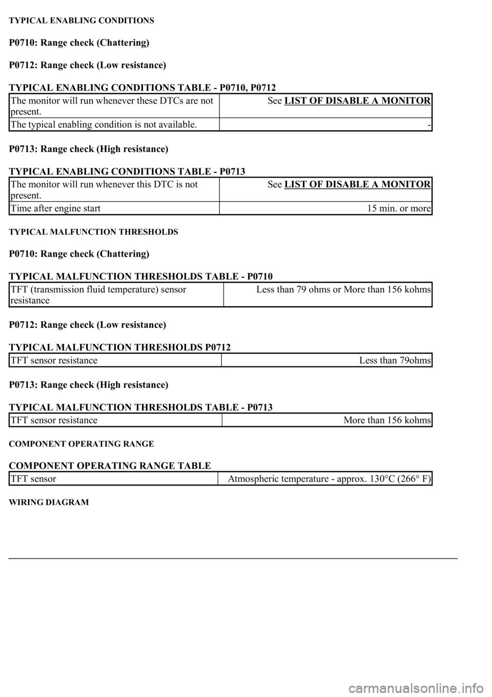
TYPICAL ENABLING CONDITIONS
P0710: Range check (Chattering)
P0712: Range check (Low resistance)
TYPICAL ENABLING CONDITIONS TABLE - P0710, P0712
P0713: Range check (High resistance)
TYPICAL ENABLING CONDITIONS TABLE - P0713
TYPICAL MALFUNCTION THRESHOLDS
P0710: Range check (Chattering)
TYPICAL MALFUNCTION THRESHOLDS TABLE - P0710
P0712: Range check (Low resistance)
TYPICAL MALFUNCTION THRESHOLDS P0712
P0713: Range check (High resistance)
TYPICAL MALFUNCTION THRESHOLDS TABLE - P0713
COMPONENT OPERATING RANGE
COMPONENT OPERATING RANGE TABLE
WIRING DIAGRAM
The monitor will run whenever these DTCs are not
present.See LIST OF DISABLE A MONITOR
The typical enabling condition is not available.-
The monitor will run whenever this DTC is not
present.See LIST OF DISABLE A MONITOR
Time after engine start15 min. or more
TFT (transmission fluid temperature) sensor
resistanceLess than 79 ohms or More than 156 kohms
TFT sensor resistanceLess than 79ohms
TFT sensor resistanceMore than 156 kohms
TFT sensorAtmospheric temperature - approx. 130°C (266° F)
Page 2744 of 4500
Fig. 60: DTCs P0710, P0712, P0713 - Wiring Diagram
Courtesy of TOYOTA MOTOR SALES, U.S.A., INC.
INSPECTION PROCEDURE
HINT:
According to the DATA LIST displayed by the hand-held tester, you can read the value of the switch, sensor
actuator and so on without parts removal. Reading the DATA LIST as the first step of troubleshooting is one
method to shorten labor time.
a. Warm up the engine.
b. Turn the ignition switch off.
c. Connect the hand-held tester together with the CAN VIM (controller area network vehicle interface
module) to the DLC3.
d. Turn the ignition switch to the ON position.
e. Push the "ON" button of the hand-held tester.
f. Select the item "DIAGNOSIS/ENHANCED OBD II/DATA LIST".
g. According to the display on tester, read the "DATA LIST".
Page 2749 of 4500
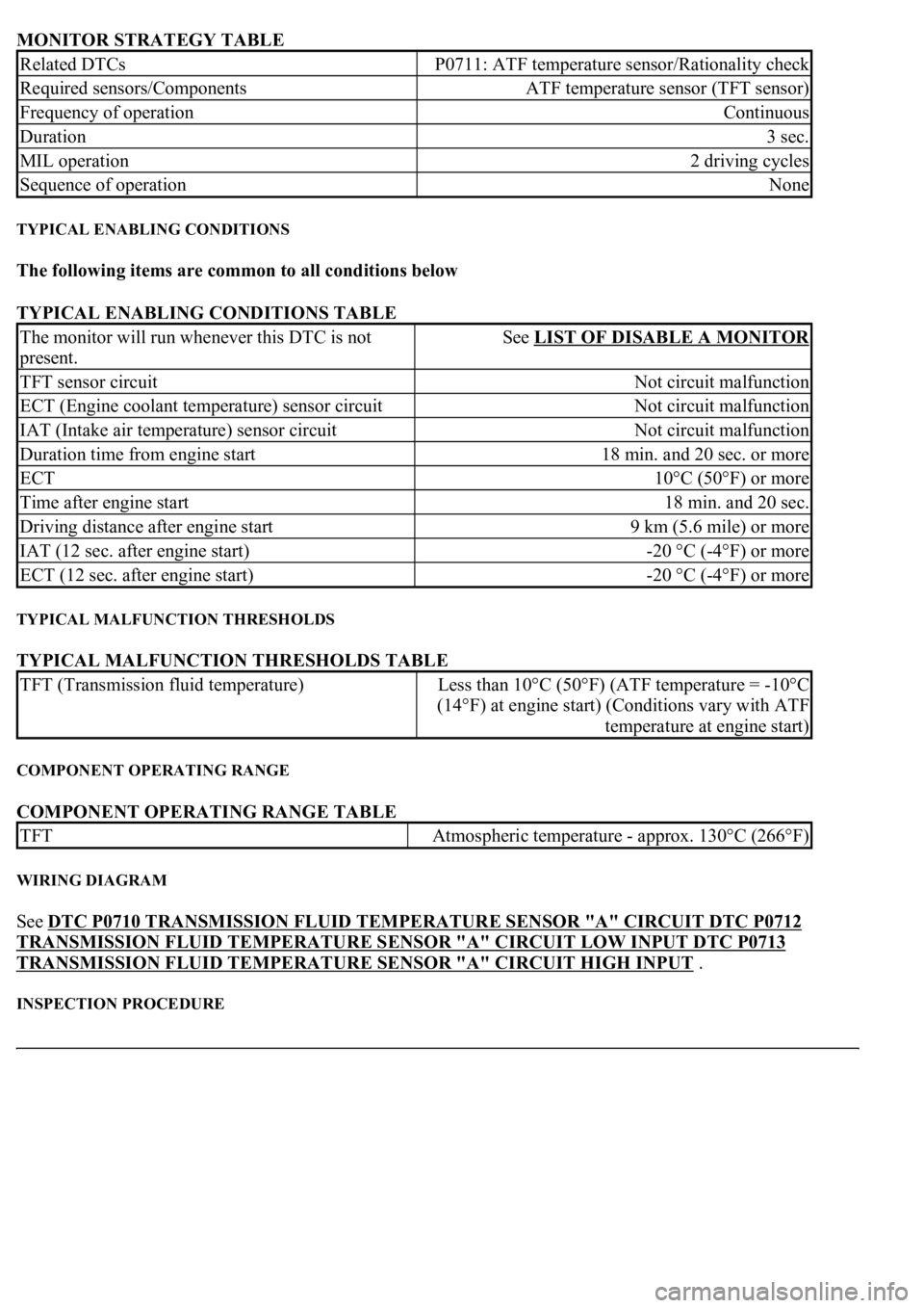
MONITOR STRATEGY TABLE
TYPICAL ENABLING CONDITIONS
The following items are common to all conditions below
TYPICAL ENABLING CONDITIONS TABLE
TYPICAL MALFUNCTION THRESHOLDS
TYPICAL MALFUNCTION THRESHOLDS TABLE
COMPONENT OPERATING RANGE
COMPONENT OPERATING RANGE TABLE
WIRING DIAGRAM
See DTC P0710 TRANSMISSION FLUID TEMPERATURE SENSOR "A" CIRCUIT DTC P0712
TRANSMISSION FLUID TEMPERATURE SENSOR "A" CIRCUIT LOW INPUT DTC P0713
TRANSMISSION FLUID TEMPERATURE SENSOR "A" CIRCUIT HIGH INPUT .
INSPECTION PROCEDURE
Related DTCsP0711: ATF temperature sensor/Rationality check
Required sensors/ComponentsATF temperature sensor (TFT sensor)
Frequency of operationContinuous
Duration3 sec.
MIL operation2 driving cycles
Sequence of operationNone
The monitor will run whenever this DTC is not
present.See LIST OF DISABLE A MONITOR
TFT sensor circuitNot circuit malfunction
ECT (Engine coolant temperature) sensor circuitNot circuit malfunction
IAT (Intake air temperature) sensor circuitNot circuit malfunction
Duration time from engine start18 min. and 20 sec. or more
ECT10°C (50°F) or more
Time after engine start18 min. and 20 sec.
Driving distance after engine start9 km (5.6 mile) or more
IAT (12 sec. after engine start)-20 °C (-4°F) or more
ECT (12 sec. after engine start)-20 °C (-4°F) or more
TFT (Transmission fluid temperature)Less than 10°C (50°F) (ATF temperature = -10°C
(14°F) at engine start) (Conditions vary with ATF
temperature at engine start)
TFTAtmospheric temperature - approx. 130°C (266°F)
Page 2750 of 4500
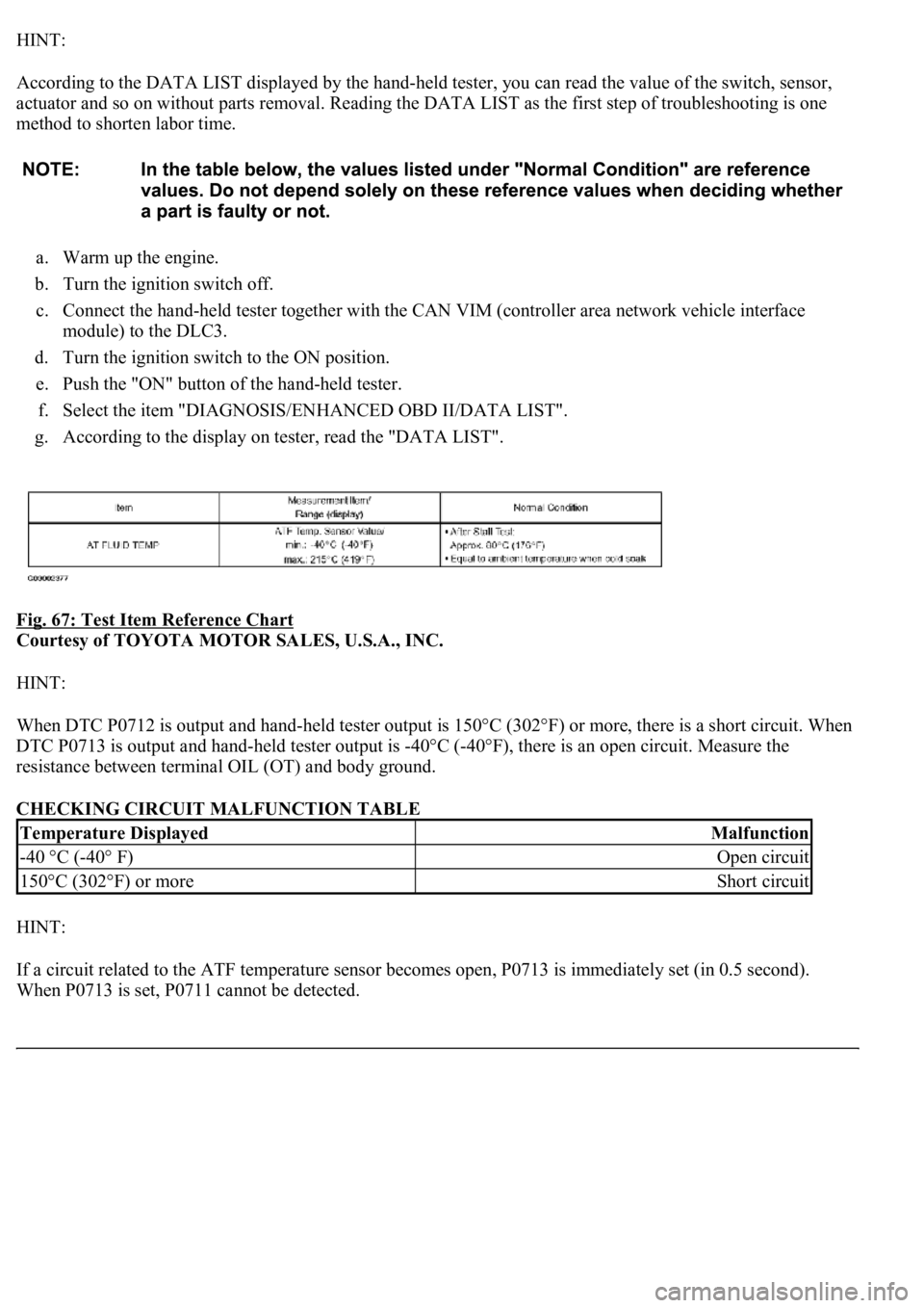
HINT:
According to the DATA LIST displayed by the hand-held tester, you can read the value of the switch, sensor,
actuator and so on without parts removal. Reading the DATA LIST as the first step of troubleshooting is one
method to shorten labor time.
a. Warm up the engine.
b. Turn the ignition switch off.
c. Connect the hand-held tester together with the CAN VIM (controller area network vehicle interface
module) to the DLC3.
d. Turn the ignition switch to the ON position.
e. Push the "ON" button of the hand-held tester.
f. Select the item "DIAGNOSIS/ENHANCED OBD II/DATA LIST".
g. According to the display on tester, read the "DATA LIST".
Fig. 67: Test Item Reference Chart
Courtesy of TOYOTA MOTOR SALES, U.S.A., INC.
HINT:
<003a004b004800510003002700370026000300330013001a001400150003004c0056000300520058005700530058005700030044005100470003004b0044005100470010004b0048004f004700030057004800560057004800550003005200580057005300
5800570003004c00560003001400180013008300260003000b[302°F) or more, there is a short circuit. When
DTC P0713 is output and hand-held tester output is -40°C (-40°F), there is an open circuit. Measure the
resistance between terminal OIL (OT) and body ground.
CHECKING CIRCUIT MALFUNCTION TABLE
HINT:
If a circuit related to the ATF temperature sensor becomes open, P0713 is immediately set (in 0.5 second).
When P0713 is set, P0711 cannot be detected.
Temperature DisplayedMalfunction
-40 °C (-40° F)Open circuit
150°C (302°F) or moreShort circuit
Page 2751 of 4500
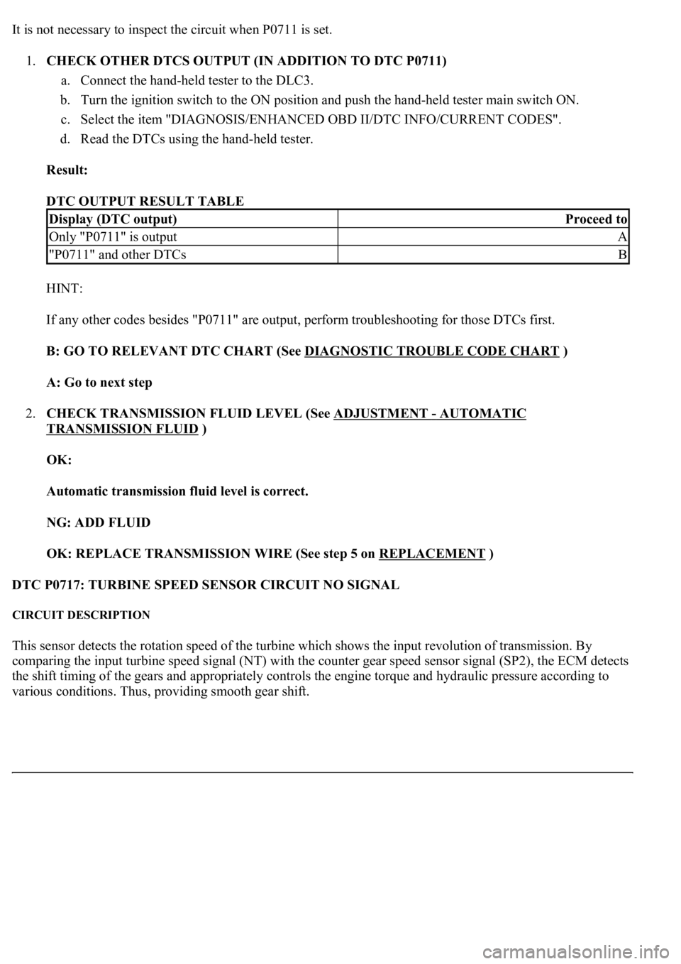
It is not necessary to inspect the circuit when P0711 is set.
1.CHECK OTHER DTCS OUTPUT (IN ADDITION TO DTC P0711)
a. Connect the hand-held tester to the DLC3.
b. Turn the ignition switch to the ON position and push the hand-held tester main switch ON.
c. Select the item "DIAGNOSIS/ENHANCED OBD II/DTC INFO/CURRENT CODES".
d. Read the DTCs using the hand-held tester.
Result:
DTC OUTPUT RESULT TABLE
HINT:
If any other codes besides "P0711" are output, perform troubleshooting for those DTCs first.
B: GO TO RELEVANT DTC CHART (See DIAGNOSTIC TROUBLE CODE CHART
)
A: Go to next step
2.CHECK TRANSMISSION FLUID LEVEL (See ADJUSTMENT
- AUTOMATIC
TRANSMISSION FLUID )
OK:
Automatic transmission fluid level is correct.
NG: ADD FLUID
OK: REPLACE TRANSMISSION WIRE (See step 5 on REPLACEMENT
)
DTC P0717: TURBINE SPEED SENSOR CIRCUIT NO SIGNAL
CIRCUIT DESCRIPTION
This sensor detects the rotation speed of the turbine which shows the input revolution of transmission. By
comparing the input turbine speed signal (NT) with the counter gear speed sensor signal (SP2), the ECM detects
the shift timing of the gears and appropriately controls the engine torque and hydraulic pressure according to
various conditions. Thus, providin
g smooth gear shift.
Display (DTC output)Proceed to
Only "P0711" is outputA
"P0711" and other DTCsB