Page 1818 of 4500

PROCEED WITH TROUBLESHOOTING) and A/C system (see HOW TO PROCEED WITH
TROUBLESHOOTING ).
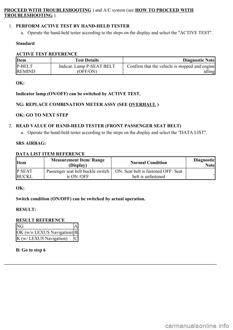
1.PERFORM ACTIVE TEST BY HAND-HELD TESTER
a. Operate the hand-held tester according to the steps on the display and select the "ACTIVE TEST".
Standard
ACTIVE TEST REFERENCE
OK:
Indicator lamp (ON/OFF) can be switched by ACTIVE TEST.
NG: REPLACE COMBINATION METER ASSY (SEE OVERHAUL
)
OK: GO TO NEXT STEP
2.READ VALUE OF HAND-HELD TESTER (FRONT PASSENGER SEAT BELT)
a. Operate the hand-held tester according to the steps on the display and select the "DATA LIST".
SRS AIRBAG:
DATA LIST ITEM REFERENCE
OK:
Switch condition (ON/OFF) can be switched by actual operation.
RESULT:
RESULT REFERENCE
B: Go to step 6
ItemTest DetailsDiagnostic Note
P-BELT
REMINDIndicat. Lamp P-SEAT BELT
(OFF/ON)Confirm that the vehicle is stopped and engine
idling
ItemMeasurement Item/ Range
(Display)Normal ConditionDiagnostic
Note
P SEAT
BUCKLPassenger seat belt buckle switch
is ON /OFFON: Seat belt is fastened OFF: Seat
belt is unfastened-
NGA
OK (w/o LEXUS Navigation)B
K (w/ LEXUS Navigation)C
Page 1828 of 4500
OK: GO TO NEXT STEP
10.INSPECT MULTI-DISPLAY
a. Disconnect the multi-display connector.
b. Measure the voltage according to the value (s) in the table below.
Standard
MULTI-DISPLAY CONNECTOR TERMINALS VOLTAGE SPECIFICATIONS
NG: REPAIR OR REPLACE HARNESS OR CONNECTOR
Fig. 78: Identifying Multi
-Display Connector Terminals
Courtesy of TOYOTA MOTOR SALES, U.S.A., INC.
Terminal NoConditionSpecified condition
M4-21 - M4-3Ignition switch ON, Passenger seat belt is unfastened10 to 14 V
Page 1829 of 4500
OK: REPLACE MULTI-DISPLAY
11.CHECK HARNESS AND CONNECTOR (MULTI-DISPLAY - COMBINATION METER ASSY)
(SEE HOW TO PROCEED WITH TROUBLESHOOTING
)
a. Disconnect the M4 and C12 connectors.
b. Measure the resistance according to the value (s) in the table below.
Standard
M4 AND C12 CONNECTORS RESISTANCE SPECIFICATIONS
Tester ConnectionConditionSpecified Condition
C12-9 - M4-21AlwaysBelow 1 ohms
C12-9 - Body groundAlways10 kohms or higher
Page 1831 of 4500
Fig. 79: Identifying M4 And C12 Connector Terminals
Courtesy of TOYOTA MOTOR SALES, U.S.A., INC.
NG: REPAIR OR REPLACE HARNESS OR CONNECTOR
OK: REPLACE COMBINATION METER ASSY (SEE OVERHAUL
)
WIRING DIAGRAM
Fig. 80: ODO/TRIP Switch Wiring Diagram
Courtesy of TOYOTA MOTOR SALES, U.S.A., INC.
INSPECTION PROCEDURE
1.READ VALUE OF HAND-HELD TESTER
a. Operate the hand-held tester according to the steps on the display and select the "DATA LIST".
METER:
DATA LIST REFERENCE
ItemMeasurement Item/ Range (Display)Normal ConditionDiagnostic Note
ODO/TRIP SWODO/TRIP switch is ON / OFFON: Switch is pushed
OFF: Switch is released-
TRIP RESET SWTRIP RESET switch is ON / OFFON: Switch is pushed
OFF: Switch is released-
Page 1835 of 4500
Fig. 82: Identifying C12 And T10 Connector Terminals
Courtesy of TOYOTA MOTOR SALES, U.S.A., INC.
NG: REPAIR OR REPLACE HARNESS OR CONNECTOR
OK: REPLACE COMBINATION METER ASSY (SEE OVERHAUL
)
WIRING DIAGRAM
Fig. 83: Light Control Rheostat Wiring Diagram
Courtesy of TOYOTA MOTOR SALES, U.S.A., INC.
INSPECTION PROCEDURE
1.READ VALUE OF HAND-HELD TESTER (LIGHT RHEOSTAT SIGNAL)
a. Operate the hand-held tester according to the steps on the display and select the "DATA LIST".
METER:
DATA LIST REFERENCE
ItemMeasurement Item/ Range
(Display)Normal ConditionDiagnostic
Note
LIGHT
RHEOSTATLight control rheostat / Min.: 0,
Max.: 255Light control rheostat switch is Dark
(0) --> Bright (255)-
Page 1836 of 4500

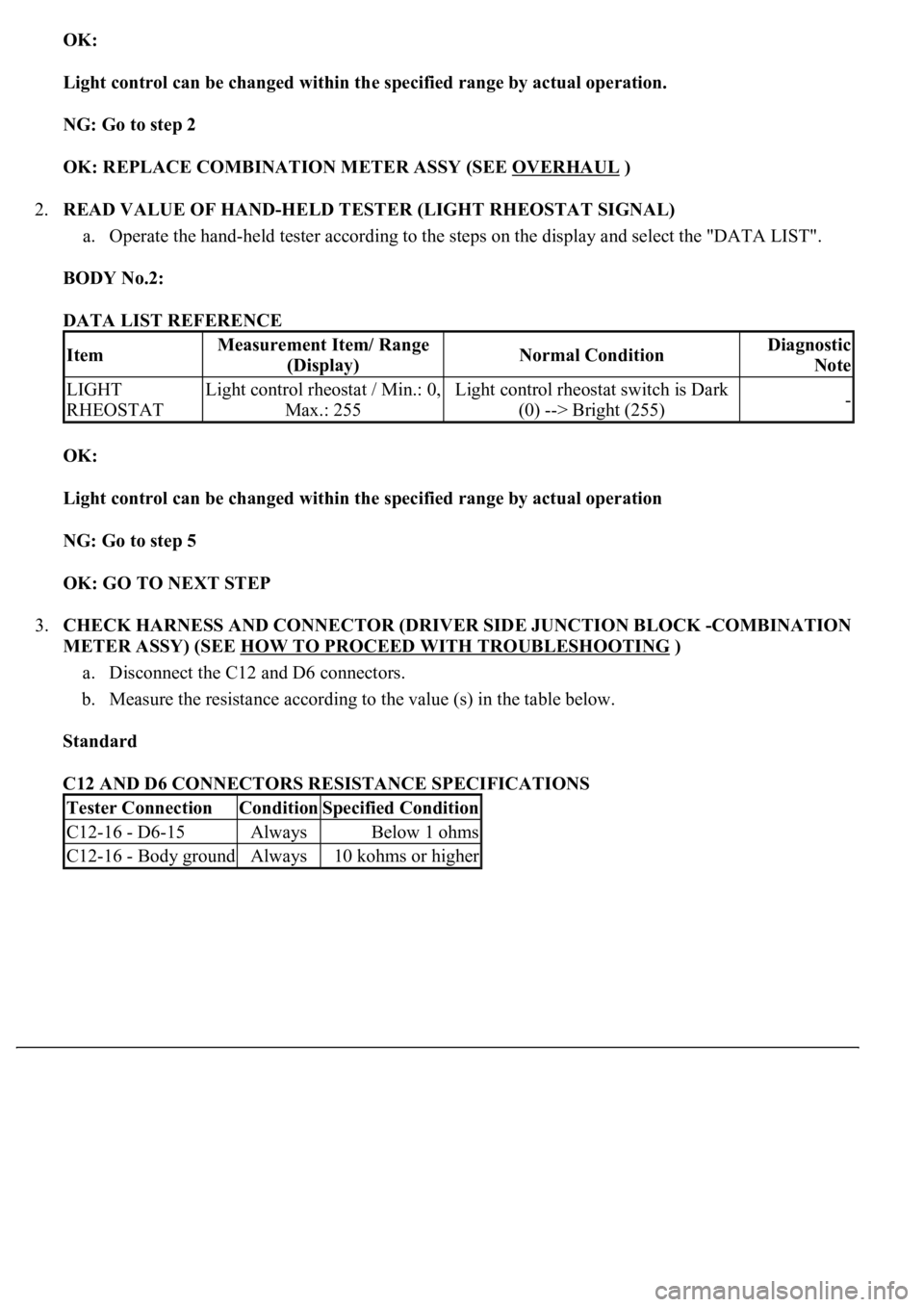
OK:
Light control can be changed within the specified range by actual operation.
NG: Go to step 2
OK: REPLACE COMBINATION METER ASSY (SEE OVERHAUL
)
2.READ VALUE OF HAND-HELD TESTER (LIGHT RHEOSTAT SIGNAL)
a. Operate the hand-held tester according to the steps on the display and select the "DATA LIST".
BODY No.2:
DATA LIST REFERENCE
OK:
Light control can be changed within the specified range by actual operation
NG: Go to step 5
OK: GO TO NEXT STEP
3.CHECK HARNESS AND CONNECTOR (DRIVER SIDE JUNCTION BLOCK -COMBINATION
METER ASSY) (SEE HOW TO PROCEED WITH TROUBLESHOOTING
)
a. Disconnect the C12 and D6 connectors.
b. Measure the resistance according to the value (s) in the table below.
Standard
C12 AND D6 CONNECTORS RESISTANCE SPECIFICATIONS
ItemMeasurement Item/ Range
(Display)Normal ConditionDiagnostic
Note
LIGHT
RHEOSTATLight control rheostat / Min.: 0,
Max.: 255Light control rheostat switch is Dark
(0) --> Bright (255)-
Tester ConnectionConditionSpecified Condition
C12-16 - D6-15AlwaysBelow 1 ohms
C12-16 - Body groundAlways10 kohms or higher
Page 1848 of 4500

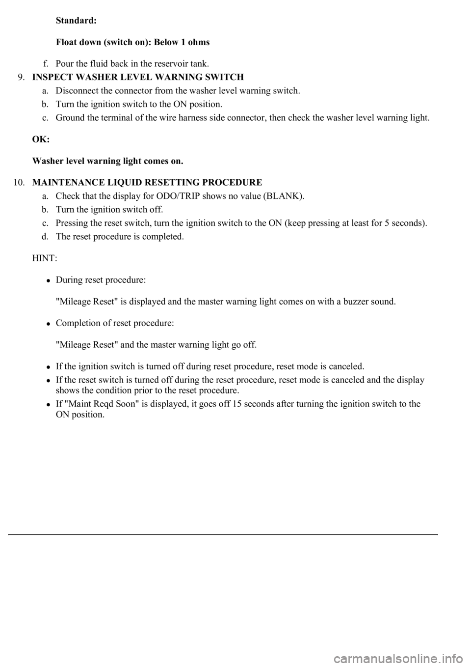
Standard:
Float down (switch on): Below 1 ohms
f. Pour the fluid back in the reservoir tank.
9.INSPECT WASHER LEVEL WARNING SWITCH
a. Disconnect the connector from the washer level warning switch.
b. Turn the ignition switch to the ON position.
c. Ground the terminal of the wire harness side connector, then check the washer level warning light.
OK:
Washer level warning light comes on.
10.MAINTENANCE LIQUID RESETTING PROCEDURE
a. Check that the display for ODO/TRIP shows no value (BLANK).
b. Turn the ignition switch off.
c. Pressing the reset switch, turn the ignition switch to the ON (keep pressing at least for 5 seconds).
d. The reset procedure is completed.
HINT:
During reset procedure:
"Mileage Reset" is displayed and the master warning light comes on with a buzzer sound.
Completion of reset procedure:
"Mileage Reset" and the master warning light go off.
If the ignition switch is turned off during reset procedure, reset mode is canceled.
If the reset switch is turned off during the reset procedure, reset mode is canceled and the display
shows the condition prior to the reset procedure.
If "Maint Reqd Soon" is displayed, it goes off 15 seconds after turning the ignition switch to the
ON position.
Page 1913 of 4500
Fig. 9: Checking RES (RESUME) Function
Courtesy of TOYOTA MOTOR SALES, U.S.A., INC.
If a normal system code is displayed during the DTC check but the problem still occurs, check the circuits for
each problem symptom in the order given in the table below and proceed to the relevant troubleshooting page.
HINT:
Inspect the "Fuse" and "Relay" before confirming the suspected areas as shown in the chart below.
Inspect each malfunction circuit in numerical order for the correspondin
g symptom.