Page 2225 of 4500
NG: REPAIR OR REPLACE HARNESS AND CONNECTOR
OK: PROCEED TO NEXT CIRCUIT INSPECTION SHOWN ON PROBLEM SYMPTOMS
TABLE
CIRCUIT DESCRIPTION
The door lock assembly has a built-in closer position switch, which detects the position of the closer.
WIRING DIAGRAM
Fig. 54: Door Closer Position Switch Circuit On Driver Side Door
- Wiring Diagram
Courtesy of TOYOTA MOTOR SALES, U.S.A., INC.
INSPECTION PROCEDURE
1.READ VALUE OF DATA LIST (DOOR CLOSER POSITION SWITCH (POLE/HALF/ FULL))
a. Check the DATA LIST for proper functioning of the door closer position switch.
DRIVER DOOR EC
R14-1 (CPUB) - Body groundAlways10 to 14 V
R14-2 (BDR) - Body groundAlways10 to 14 V
R14-26 (SIG) Body groundIgnition switch ON10 to 14 V
Measurement item / Display
Page 2233 of 4500

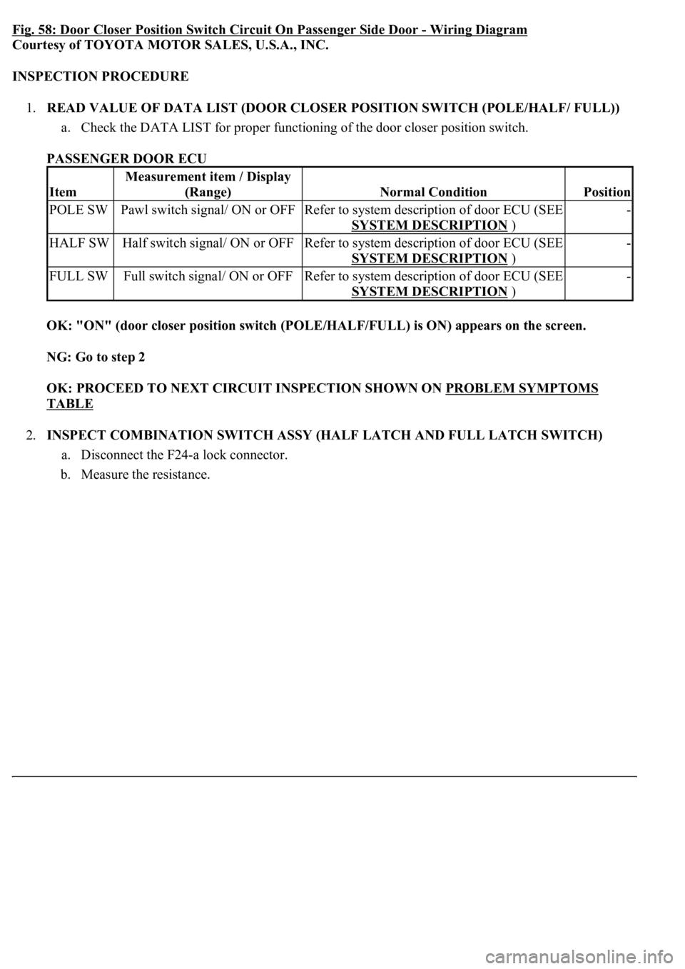
Fig. 58: Door Closer Position Switch Circuit On Passenger Side Door -Wiring Diagram
Courtesy of TOYOTA MOTOR SALES, U.S.A., INC.
INSPECTION PROCEDURE
1.READ VALUE OF DATA LIST (DOOR CLOSER POSITION SWITCH (POLE/HALF/ FULL))
a. Check the DATA LIST for proper functioning of the door closer position switch.
PASSENGER DOOR ECU
OK: "ON" (door closer position switch (POLE/HALF/FULL) is ON) appears on the screen.
NG: Go to step 2
OK: PROCEED TO NEXT CIRCUIT INSPECTION SHOWN ON PROBLEM SYMPTOMS
TABLE
2.INSPECT COMBINATION SWITCH ASSY (HALF LATCH AND FULL LATCH SWITCH)
a. Disconnect the F24-a lock connector.
b. Measure the resistance.
Item
Measurement item / Display
(Range)
Normal ConditionPosition
POLE SWPawl switch signal/ ON or OFFRefer to system description of door ECU (SEE
SYSTEM DESCRIPTION
)
-
HALF SWHalf switch signal/ ON or OFFRefer to system description of door ECU (SEE
SYSTEM DESCRIPTION
)
-
FULL SWFull switch signal/ ON or OFFRefer to system description of door ECU (SEE
SYSTEM DESCRIPTION
)
-
Page 2239 of 4500
Fig. 61: Checking Wire Harness (Passenger Door ECU -Front Door Lock Assy RH)
Courtesy of TOYOTA MOTOR SALES, U.S.A., INC.
NG: REPLACE COMBINATION SWITCH ASSY
OK: PROCEED TO NEXT CIRCUIT INSPECTION SHOWN ON PROBLEM SYMPTOMS
TABLE
CIRCUIT DESCRIPTION
The door lock assembly has a built-in closer position switch, which detects the position of the closer.
WIRING DIAGRAM
Fig. 62: Door Closer Position Switch Circuit On Rear Left Side Door
- Wiring Diagram
Courtesy of TOYOTA MOTOR SALES, U.S.A., INC.
INSPECTION PROCEDURE
1.READ VALUE OF DATA LIST (DOOR CLOSER POSITION SWITCH (POLE/HALF/ FULL))
a. Check the DATA LIST for proper functioning of the door closer position switch.
REAR DOOR LH ECU
Item
Measurement item / Display
(Range)
Normal ConditionPosition
POLE SWPawl switch signal/ ON or OFFRefer to system description of door ECU -
Page 2246 of 4500
Fig. 65: Checking Wire Harness (Rear Door LH ECU -Rear Door Lock Assy LH)
Courtesy of TOYOTA MOTOR SALES, U.S.A., INC.
NG: REPLACE COMBINATION SWITCH ASSY
OK: PROCEED TO NEXT CIRCUIT INSPECTION SHOWN ON PROBLEM SYMPTOMS
TABLE
CIRCUIT DESCRIPTION
The door lock assembly has a built-in closer position switch, which detects the position of the closer.
WIRING DIAGRAM
Fig. 66: Door Closer Position Switch Circuit On Rear Right Side Door
- Wiring Diagram
Courtesy of TOYOTA MOTOR SALES, U.S.A., INC.
INSPECTION PROCEDURE
1.READ VALUE OF DATA LIST (DOOR CLOSER POSITION SWITCH (POLE/HALF/ FULL))
1. Check the DATA LIST for proper functioning of the door closer position switch and lock position
switch.
REAR DOOR ECU RH
Item
Measurement item / Display
(Range)
Normal ConditionPosition
Page 2426 of 4500

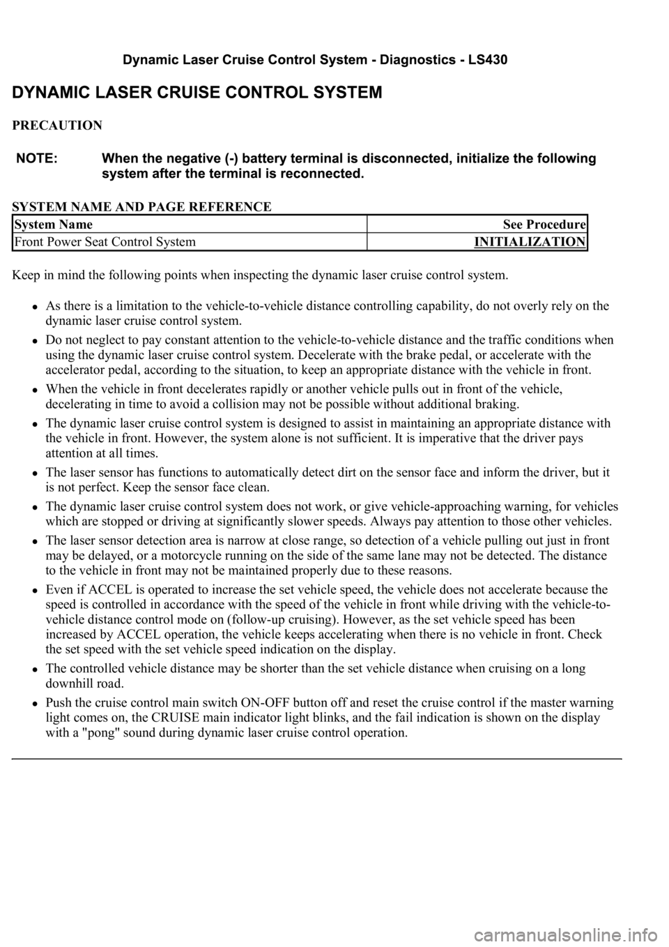
PRECAUTION
SYSTEM NAME AND PAGE REFERENCE
Keep in mind the following points when inspecting the dynamic laser cruise control system.
As there is a limitation to the vehicle-to-vehicle distance controlling capability, do not overly rely on the
dynamic laser cruise control system.
Do not neglect to pay constant attention to the vehicle-to-vehicle distance and the traffic conditions when
using the dynamic laser cruise control system. Decelerate with the brake pedal, or accelerate with the
accelerator pedal, according to the situation, to keep an appropriate distance with the vehicle in front.
When the vehicle in front decelerates rapidly or another vehicle pulls out in front of the vehicle,
decelerating in time to avoid a collision may not be possible without additional braking.
The dynamic laser cruise control system is designed to assist in maintaining an appropriate distance with
the vehicle in front. However, the system alone is not sufficient. It is imperative that the driver pays
attention at all times.
The laser sensor has functions to automatically detect dirt on the sensor face and inform the driver, but it
is not perfect. Keep the sensor face clean.
The dynamic laser cruise control system does not work, or give vehicle-approaching warning, for vehicles
which are stopped or driving at significantly slower speeds. Always pay attention to those other vehicles.
The laser sensor detection area is narrow at close range, so detection of a vehicle pulling out just in front
may be delayed, or a motorcycle running on the side of the same lane may not be detected. The distance
to the vehicle in front may not be maintained properly due to these reasons.
Even if ACCEL is operated to increase the set vehicle speed, the vehicle does not accelerate because the
speed is controlled in accordance with the speed of the vehicle in front while driving with the vehicle-to-
vehicle distance control mode on (follow-up cruising). However, as the set vehicle speed has been
increased by ACCEL operation, the vehicle keeps accelerating when there is no vehicle in front. Check
the set speed with the set vehicle speed indication on the display.
The controlled vehicle distance may be shorter than the set vehicle distance when cruising on a long
downhill road.
Push the cruise control main switch ON-OFF button off and reset the cruise control if the master warning
light comes on, the CRUISE main indicator light blinks, and the fail indication is shown on the display
with a "pong" sound during dynamic laser cruise control operation.
System NameSee Procedure
Front Power Seat Control SystemINITIALIZATION
Page 2434 of 4500
Fig. 6: Dynamic Laser Cruise Control System Control Example Chart
Courtesy of TOYOTA MOTOR SALES, U.S.A., INC.
Setting of the vehicle distance can be changed to 3 distances by operating the distance control
switch (DISP2 button): long (approximately 75 m (246 ft)), middle (approximately 50 m (164 ft)),
and short (approximately 30 m (98 ft)) when vehicle speed is approximately 90 km/h (55 mph).
HINT:
Vehicle distance increases and decreases in accordance with vehicle speed.
Controlling condition is indicated on the combination meter multi-information display.
2.FUNCTION OF MAIN COMPONENTS
Page 2447 of 4500
Fig. 15: Identifying Cruise Control Main Switch
Courtesy of TOYOTA MOTOR SALES, U.S.A., INC.
2.INSPECT MODE SWITCH
a. Turn the ignition switch to the ON position.
HINT:
Dynamic laser cruise system is in the default mode.
b. After pushing the ON-OFF button on, push the cruise control main switch to MODE for at least 1
second without any other control. Make sure that only "NORM." and nothing else is indicated on
the display.
Page 2449 of 4500
Fig. 17: [Display NORM]
Courtesy of TOYOTA MOTOR SALES, U.S.A., INC.
3.INSPECT STEERING PAD SWITCH ASSY
a. Turn the ignition switch to the ON position.
b. Push on the ON-OFF button of the cruise control main switch.
c. Push on the distance control switch (DISP2) of the steering pad switch.
d. Check that the indication of vehicle-to-vehicle distance, which is shown in the multi-information
displa
y on the combination meter, changes from "LONG", "MIDDLE" to "SHORT" in that order.