Page 1962 of 4500
Fig. 15: Confirming Current Value Of Laser Beam
Courtesy of TOYOTA MOTOR SALES, U.S.A., INC.
13. Press the "ENTER" key.
HINT:
*1: Either UPPER or LOWER is indicated.
*2: Either LEFT or RIGHT is indicated.
*3: Values between 0.0 and 6.3 are indicated.
The direction and angle that actually deviate from the spec are displayed in the multi-information
display on the combination meter when starting the optical axis adjustment mode with the hand-
held tester.
14. Move the reflector either to the right or left by 100 mm (3.937 in.) and check that the value
changes.
Page 1963 of 4500
15. Return the reflector to the original position and read the current angle.
DIVERGENCE OF BEAM AXIS TABLE
HINT:
When the values displayed on the screen are normal, the values are within the above range. If the
value is out of range, check the installation condition of the bumper reinforcement, etc.
16. Turn the headlamp dimmer switch to the TAIL position.
17. Press the "ENTER" key.
Fig. 16: Identifying "ENTER" Key
UPPER/LOWER SIDE-2° TO +2°
RIGHT/LEFT SIDE-4° TO +4°
Page 1980 of 4500
Fig. 34: Pressing ENTER" Key
Courtesy of TOYOTA MOTOR SALES, U.S.A., INC.
13. Confirm that the current distance (reference value) is approximately 5 m (16.41 ft).
HINT:
If the distance is 0 m, the sensor can not detect the target. Reconfirm that there is no metal in the
region.
*1: Either DISTANCE is indicated.
*2: Either LEFT or RIGHT is indicated.
<000d0016001d000300390044004f0058004800560003004500480057005a00480048005100030013001100130003004400510047000300190011001600030044005500480003004c00510047004c004600440057004800470011000300240047004d005800
56005700030057004b00480003005500440047004400550003[beam axis so that the value
falls between 4.0 and 6.0.
*4: Values between 0.0 and 6.3 are indicated.
The direction and angle that actually deviate from the spec are displayed in the multi-information
Page 1981 of 4500
display on the combination meter when starting the beam axis adjustment mode with the hand-held
tester.
Fig. 35: Confirming Current Distance
Courtesy of TOYOTA MOTOR SALES, U.S.A., INC.
g. Adjustment in horizontal direction
1. Read the divergence in the current angle.
Standard:
0° (Both right and left)
2. Based on the measured divergence of the beam axis, turn and adjust screw B for horizontal
adjustment of the millimeter wave radar sensor using a hexagon wrench.
HINT:
Page 1982 of 4500
If "LEFT SIDE: 0.6°" is displayed, the divergence is 0.6° in the left direction. Give the screw
approximately 3 turns to the positive (+) side.
Fig. 36: Adjusting In Horizontal Direction
Courtesy of TOYOTA MOTOR SALES, U.S.A., INC.
Result:
Fig. 37: Adjustment Direction Chart
Page 1991 of 4500
Fig. 2: Defogger System Diagram
Courtesy of TOYOTA MOTOR SALES, U.S.A., INC.
Communication Table
COMMUNICATION TABLE
1.GENERAL
The rear window defogger system's thin heater wires are attached to the inside of the rear window and
defog the window surface quickly. The indicator lamp illuminates while the system is operating. The
system automatically turns off after approximately 15 minutes.
2.FUNCTION OF MAIN COMPONENT
SenderReceiverSignalLine
Multi-display(1)A/C control assemblyRear defogger switch
signalBEAN
Center cluster integration
panel
(2)
A/C control assemblyRear defogger switch
signalBEAN/AVC-LAN
(1)w/ LEXUS navigation system
(2)w/o LEXUS navigation system
Page 1996 of 4500

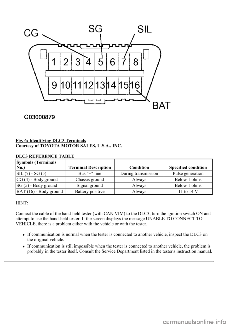
Fig. 6: Identifying DLC3 Terminals
Courtesy of TOYOTA MOTOR SALES, U.S.A., INC.
DLC3 REFERENCE TABLE
HINT:
Connect the cable of the hand-held tester (with CAN VIM) to the DLC3, turn the ignition switch ON and
attempt to use the hand-held tester. If the screen displays the message UNABLE TO CONNECT TO
VEHICLE, there is a problem either with the vehicle or with the tester.
If communication is normal when the tester is connected to another vehicle, inspect the DLC3 on
the original vehicle.
If communication is still impossible when the tester is connected to another vehicle, the problem is
probabl
y in the tester itself. Consult the Service Department listed in the tester's instruction manual.
Symbols (Terminals
No.)
Terminal DescriptionConditionSpecified condition
SIL (7) - SG (5)Bus "+" lineDuring transmissionPulse generation
CG (4) - Body groundChassis groundAlwaysBelow 1 ohms
SG (5) - Body groundSignal groundAlwaysBelow 1 ohms
BAT (16) - Body groundBattery positiveAlways11 to 14 V
Page 1998 of 4500
c. Perform the ACTIVE TEST by following the directions on the tester screen.
A/C control assy:
A/C CONTROL ASSY - REFERENCE TABLE
CIRCUIT DESCRIPTION
When the defogger switch is turned on, a rear defogger activation request signal is input to the A/C control (A/C
ECU) from the multi-display
1 or center cluster integration panel2 . Then, the A/C control assembly outputs this
signal to the defogger relay (Marking: DEFOG) and the rear window defogger system is activated.
HINT:
1. w/ LEXUS navigation system
2. w/o LEXUS navigation system
WIRING DIAGRAM
ItemTest DetailsDiagnostic Note
DEFOGGER RLY-ROperate rear window defogger OFF/ON-