2003 LEXUS LS430 actuator
[x] Cancel search: actuatorPage 2569 of 4500
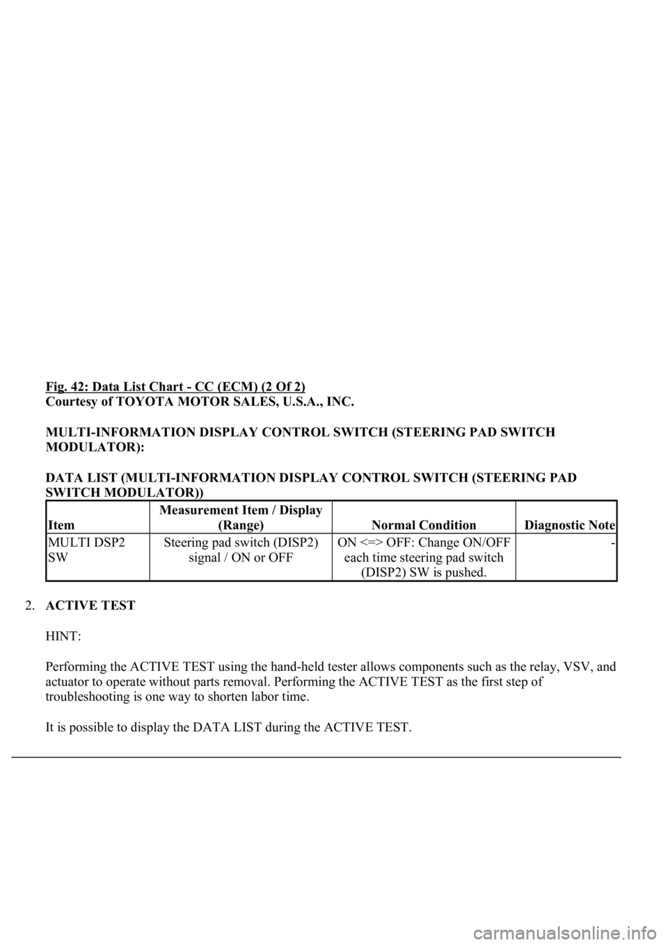
Fig. 42: Data List Chart - CC (ECM) (2 Of 2)
Courtesy of TOYOTA MOTOR SALES, U.S.A., INC.
MULTI-INFORMATION DISPLAY CONTROL SWITCH (STEERING PAD SWITCH
MODULATOR):
DATA LIST (MULTI-INFORMATION DISPLAY CONTROL SWITCH (STEERING PAD
SWITCH MODULATOR))
2.ACTIVE TEST
HINT:
Performing the ACTIVE TEST using the hand-held tester allows components such as the relay, VSV, and
actuator to operate without parts removal. Performing the ACTIVE TEST as the first step of
troubleshooting is one way to shorten labor time.
It is possible to displa
y the DATA LIST during the ACTIVE TEST.
Item
Measurement Item / Display
(Range)
Normal ConditionDiagnostic Note
MULTI DSP2
SWSteering pad switch (DISP2)
signal / ON or OFFON <=> OFF: Change ON/OFF
each time steering pad switch
(DISP2) SW is pushed.-
Page 2587 of 4500
CIRCUIT DESCRIPTION
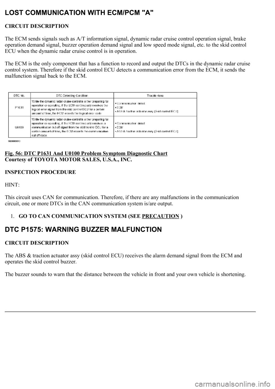
The ECM sends signals such as A/T information signal, dynamic radar cruise control operation signal, brake
operation demand signal, buzzer operation demand signal and low speed mode signal, etc. to the skid control
ECU when the dynamic radar cruise control is in operation.
<0037004b004800030028002600300003004c005600030057004b0048000300520051004f005c000300460052005000530052005100480051005700030057004b004400570003004b0044005600030044000300490058005100460057004c00520051000300
57005200030055004800460052005500470003004400510047[ output the DTCs in the dynamic radar cruise
control system. Therefore if the skid control ECU detects a communication error from the ECM, it sends the
malfunction signal back to the ECM.
Fig. 56: DTC P1631 And U0100 Problem Symptom Diagnostic Chart
Courtesy of TOYOTA MOTOR SALES, U.S.A., INC.
INSPECTION PROCEDURE
HINT:
This circuit uses CAN for communication. Therefore, if there are any malfunctions in the communication
circuit, one or more DTCs in the CAN communication system is/are output.
1.GO TO CAN COMMUNICATION SYSTEM (SEE PRECAUTION
)
CIRCUIT DESCRIPTION
The ABS & traction actuator assy (skid control ECU) receives the alarm demand signal from the ECM and
operates the skid control buzzer.
The buzzer sounds to warn that the distance between the vehicle in front and
your own vehicle is shortening.
Page 2620 of 4500
CIRCUIT DESCRIPTION
When the cruise control main switch is on, CRUISE main indicator light and READY indicator light come on.
This indicates the control condition (presence or absence of a vehicle in front, vehicle-to-vehicle distance, and
set vehicle speed) and fail-safe state through the multiplex communication system and CAN communication
system.
The master warning light and CRUISE main indicator light come on and vehicle-to-vehicle distance
information is displayed on the combination meter as the alarm buzzer sounds.
Items such as "Clean Radar Sensor", "Cruise not Available", "Check Cruise System" and "Radar Cruise Ready"
are displayed in the multi-information display on the combination meter when the ECM detects signals from
each sensor and actuator and sends them to the combination meter via CAN and BEAN.
HINT:
If the vehicle in front in the same lane significantly decreases vehicle speed or another vehicle pulls in front of
your vehicle, adequate deceleration cannot be applied and the vehicle-to-vehicle distance will shorten. At this
time, the system sounds the buzzer and the master warning light blinks to warn the driver.
Each indicator in the dynamic laser cruise control uses CAN and BEAN for communication. Therefore if there
are any malfunctions in this circuit, check for DTCs in the CAN communication and multiplex communication
systems.
INSPECTION PROCEDURE
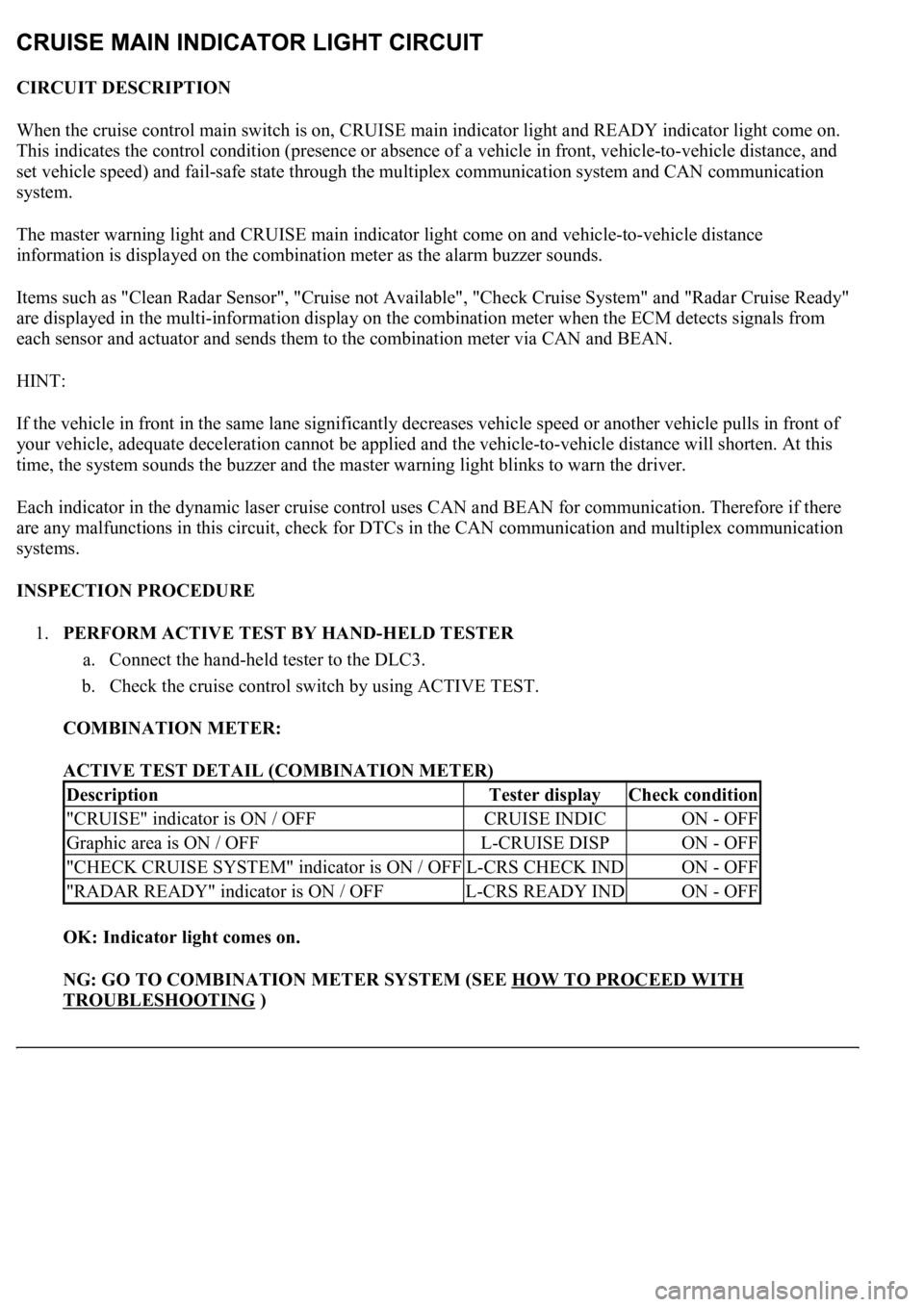
1.PERFORM ACTIVE TEST BY HAND-HELD TESTER
a. Connect the hand-held tester to the DLC3.
b. Check the cruise control switch by using ACTIVE TEST.
COMBINATION METER:
ACTIVE TEST DETAIL (COMBINATION METER)
OK: Indicator light comes on.
NG: GO TO COMBINATION METER SYSTEM (SEE HOW TO PROCEED WITH
TROUBLESHOOTING )
DescriptionTester displayCheck condition
"CRUISE" indicator is ON / OFFCRUISE INDICON - OFF
Graphic area is ON / OFFL-CRUISE DISPON - OFF
"CHECK CRUISE SYSTEM" indicator is ON / OFFL-CRS CHECK INDON - OFF
"RADAR READY" indicator is ON / OFFL-CRS READY INDON - OFF
Page 2629 of 4500
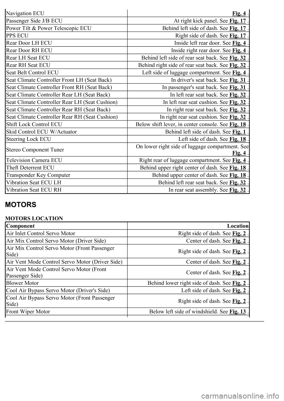
MOTORS LOCATION
Navigation ECUFig. 4 .
Passenger Side J/B ECUAt right kick panel. See Fig. 17 .
Power Tilt & Power Telescopic ECUBehind left side of dash. See Fig. 17 .
PPS ECURight side of dash. See Fig. 17 .
Rear Door LH ECUInside left rear door. See Fig. 4 .
Rear Door RH ECUInside right rear door. See Fig. 4 .
Rear LH Seat ECUBehind left side of rear seat back. See Fig. 32 .
Rear RH Seat ECUBehind right side of rear seat back. See Fig. 32 .
Seat Belt Control ECULeft side of luggage compartment. See Fig. 4 .
Seat Climate Controller Front LH (Seat Back)In driver's seat back. See Fig. 31 .
Seat Climate Controller Front RH (Seat Back)In passenger's seat back. See Fig. 31 .
Seat Climate Controller Rear LH (Seat Back)In left rear seat back. See Fig. 32 .
Seat Climate Controller Rear LH (Seat Cushion)In left rear seat cushion. See Fig. 32 .
Seat Climate Controller Rear RH (Seat Back)In right rear seat back. See Fig. 32 .
Seat Climate Controller Rear RH (Seat Cushion)In right rear seat cushion. See Fig. 32 .
Shift Lock Control ECUBelow shift lever, in center console. See Fig. 18 .
Skid Control ECU W/ActuatorBehind left side of dash. See Fig. 1 .
Steering Lock ECULeft side of dash. See Fig. 18 .
Stereo Component TunerOn lower right side of luggage compartment. See
Fig. 4
.
Television Camera ECURight rear of luggage compartment. See Fig. 4 .
Theft Deterrent ECUBehind upper right center of dash. See Fig. 18 .
Transponder Key ComputerBehind upper center of dash. See Fig. 18 .
Vibration Seat ECU LHBehind left rear seat back. See Fig. 32 .
Vibration Seat ECU RHIn rear seat assembly. See Fig. 32 .
ComponentLocation
Air Inlet Control Servo MotorRight side of dash. See Fig. 2 .
Air Mix Control Servo Motor (Driver Side)Center of dash. See Fig. 2 .
Air Mix Control Servo Motor (Front Passenger
Side)Right side of dash. See Fig. 2 .
Air Vent Mode Control Servo Motor (Driver Side)Center of dash. See Fig. 2 .
Air Vent Mode Control Servo Motor (Front
Passenger Side)Center of dash. See Fig. 2 .
Blower MotorBehind lower right side of dash. See Fig. 2 .
Cool Air Bypass Servo Motor (Driver's Side)Left side of dash. See Fig. 2 .
Cool Air Bypass Servo Motor (Front Passenger
Side)Right side of dash. See Fig. 2 .
Front Wiper MotorBelow left side of windshield. See Fig. 13 .
Page 2630 of 4500
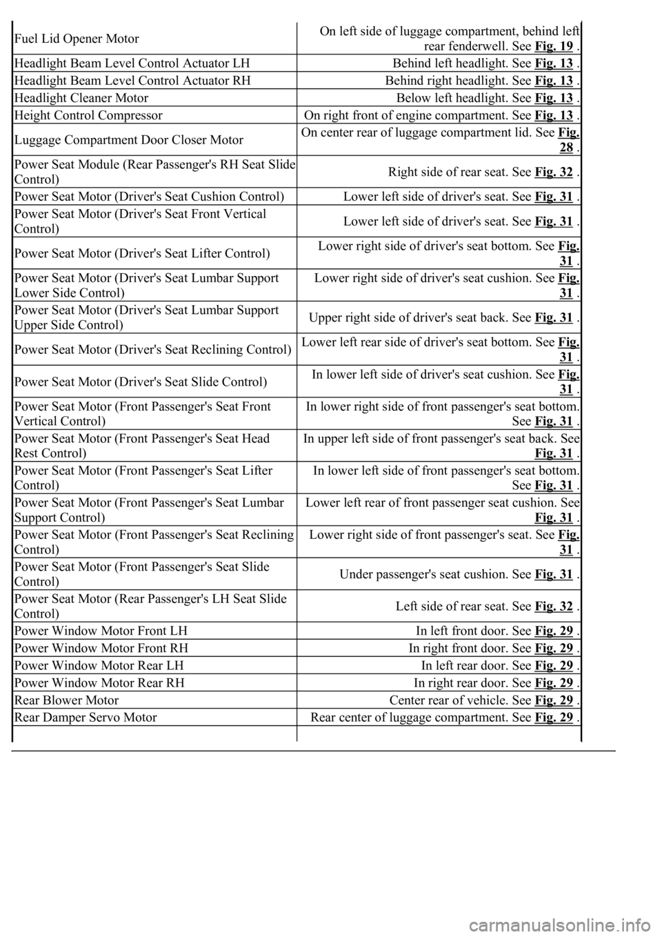
Fuel Lid Opener MotorOn left side of luggage compartment, behind left
rear fenderwell. See Fig. 19
.
Headlight Beam Level Control Actuator LHBehind left headlight. See Fig. 13 .
Headlight Beam Level Control Actuator RHBehind right headlight. See Fig. 13 .
Headlight Cleaner MotorBelow left headlight. See Fig. 13 .
Height Control CompressorOn right front of engine compartment. See Fig. 13 .
Luggage Compartment Door Closer MotorOn center rear of luggage compartment lid. See Fig.
28 .
Power Seat Module (Rear Passenger's RH Seat Slide
Control)Right side of rear seat. See Fig. 32 .
Power Seat Motor (Driver's Seat Cushion Control)Lower left side of driver's seat. See Fig. 31 .
Power Seat Motor (Driver's Seat Front Vertical
Control)Lower left side of driver's seat. See Fig. 31 .
Power Seat Motor (Driver's Seat Lifter Control)Lower right side of driver's seat bottom. See Fig.
31 .
Power Seat Motor (Driver's Seat Lumbar Support
Lower Side Control)Lower right side of driver's seat cushion. See Fig.
31 .
Power Seat Motor (Driver's Seat Lumbar Support
Upper Side Control)Upper right side of driver's seat back. See Fig. 31 .
Power Seat Motor (Driver's Seat Reclining Control)Lower left rear side of driver's seat bottom. See Fig.
31 .
Power Seat Motor (Driver's Seat Slide Control)In lower left side of driver's seat cushion. See Fig.
31 .
Power Seat Motor (Front Passenger's Seat Front
Vertical Control)In lower right side of front passenger's seat bottom.
See Fig. 31
.
Power Seat Motor (Front Passenger's Seat Head
Rest Control)In upper left side of front passenger's seat back. See
Fig. 31
.
Power Seat Motor (Front Passenger's Seat Lifter
Control)In lower left side of front passenger's seat bottom.
See Fig. 31
.
Power Seat Motor (Front Passenger's Seat Lumbar
Support Control)Lower left rear of front passenger seat cushion. See
Fig. 31
.
Power Seat Motor (Front Passenger's Seat Reclining
Control)Lower right side of front passenger's seat. See Fig.
31 .
Power Seat Motor (Front Passenger's Seat Slide
Control)Under passenger's seat cushion. See Fig. 31 .
Power Seat Motor (Rear Passenger's LH Seat Slide
Control)Left side of rear seat. See Fig. 32 .
Power Window Motor Front LHIn left front door. See Fig. 29 .
Power Window Motor Front RHIn right front door. See Fig. 29 .
Power Window Motor Rear LHIn left rear door. See Fig. 29 .
Power Window Motor Rear RHIn right rear door. See Fig. 29 .
Rear Blower MotorCenter rear of vehicle. See Fig. 29 .
Rear Damper Servo MotorRear center of luggage compartment. See Fig. 29 .
Page 2631 of 4500
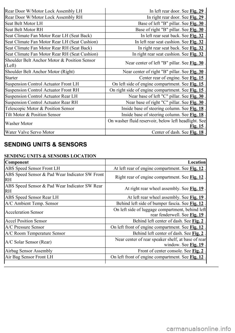
SENDING UNITS & SENSORS LOCATION
Rear Door W/Motor Lock Assembly LHIn left rear door. See Fig. 29 .
Rear Door W/Motor Lock Assembly RHIn right rear door. See Fig. 29 .
Seat Belt Motor LHBase of left "B" pillar. See Fig. 30 .
Seat Belt Motor RHBase of right "B" pillar. See Fig. 30 .
Seat Climate Fan Motor Rear LH (Seat Back)In left rear seat back. See Fig. 32 .
Seat Climate Fan Motor Rear LH (Seat Cushion)In left rear seat cushion. See Fig. 32 .
Seat Climate Fan Motor Rear RH (Seat Back)In right rear seat back. See Fig. 32 .
Seat Climate Fan Motor Rear RH (Seat Cushion)In right rear seat cushion. See Fig. 32 .
Shoulder Belt Anchor Motor & Position Sensor
(Left)Near center of left "B" pillar. See Fig. 30 .
Shoulder Belt Anchor Motor (Right)Near center of right "B" pillar. See Fig. 30 .
StarterCenter rear of engine. See Fig. 15 .
Suspension Control Actuator Front LHOn left side of engine compartment. See Fig. 15 .
Suspension Control Actuator Front RHOn right side of engine compartment. See Fig. 15 .
Suspension Control Actuator Rear LHNear base of left "C" pillar. See Fig. 30 .
Suspension Control Actuator Rear RHNear base of right "C" pillar. See Fig. 30 .
Telescopic Motor & Position SensorInside base of steering column. See Fig. 18 .
Tilt Motor & Position SensorInside base of steering column. See Fig. 18 .
Washer MotorOn washer fluid reservoir, below left headlight. See
Fig. 15
.
Water Valve Servo MotorCenter of dash. See Fig. 18 .
ComponentLocation
ABS Speed Sensor Front LHAt left rear of engine compartment. See Fig. 12 .
ABS Speed Sensor & Pad Wear Indicator SW Front
RHRight rear of engine compartment. See Fig. 12 .
ABS Speed Sensor & Pad Wear Indicator SW Rear
RHAt right rear wheel assembly. See Fig. 19 .
ABS Speed Sensor Rear LHAt left rear wheel assembly. See Fig. 19 .
A/C Ambient Temp. SensorBehind left side of bumper fascia. See Fig. 12 .
Acceleration SensorOn left side of luggage compartment, behind left
rear fenderwell. See Fig. 19
.
Accel Position SensorBehind left center of dash. See Fig. 2 .
A/C Pressure SensorOn left front of engine compartment. See Fig. 12 .
A/C Room Temperature SensorBehind left center of dash. See Fig. 2 .
A/C Solar Sensor (Rear)Near center of rear speaker shelf, at base of rear
window. See Fig. 19
.
Airbag Sensor AssemblyFront of center console. See Fig. 2 .
Air Bag Sensor Front LHOn left front of engine compartment. See Fig. 12 .
Page 2670 of 4500
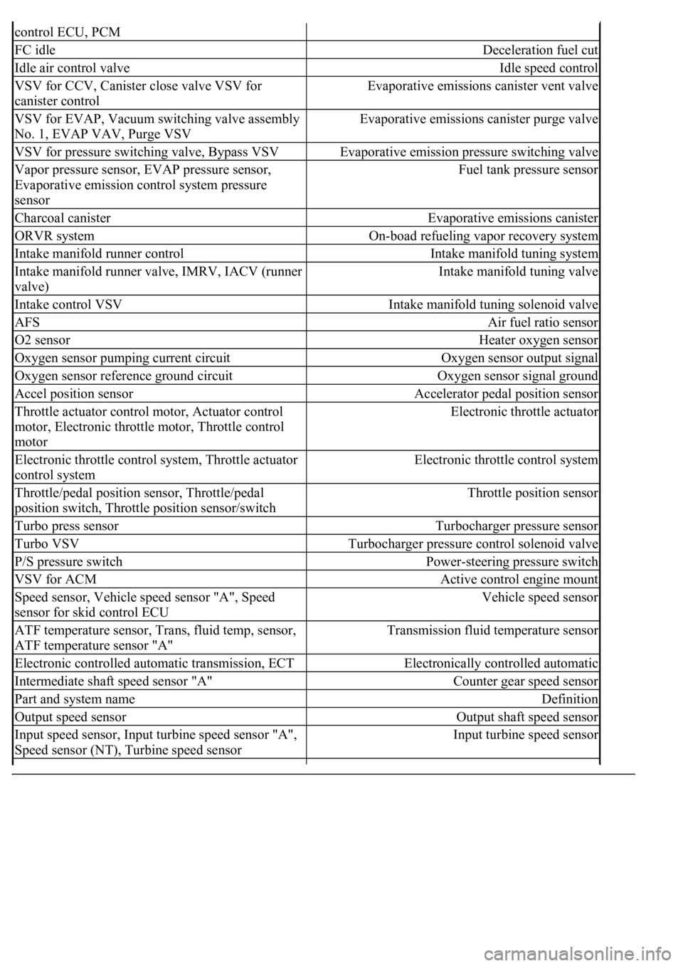
control ECU, PCM
FC idleDeceleration fuel cut
Idle air control valveIdle speed control
VSV for CCV, Canister close valve VSV for
canister controlEvaporative emissions canister vent valve
VSV for EVAP, Vacuum switching valve assembly
No. 1, EVAP VAV, Purge VSVEvaporative emissions canister purge valve
VSV for pressure switching valve, Bypass VSVEvaporative emission pressure switching valve
Vapor pressure sensor, EVAP pressure sensor,
Evaporative emission control system pressure
sensorFuel tank pressure sensor
Charcoal canisterEvaporative emissions canister
ORVR systemOn-boad refueling vapor recovery system
Intake manifold runner controlIntake manifold tuning system
Intake manifold runner valve, IMRV, IACV (runner
valve)Intake manifold tuning valve
Intake control VSVIntake manifold tuning solenoid valve
AFSAir fuel ratio sensor
O2 sensorHeater oxygen sensor
Oxygen sensor pumping current circuitOxygen sensor output signal
Oxygen sensor reference ground circuitOxygen sensor signal ground
Accel position sensorAccelerator pedal position sensor
Throttle actuator control motor, Actuator control
motor, Electronic throttle motor, Throttle control
motorElectronic throttle actuator
Electronic throttle control system, Throttle actuator
control systemElectronic throttle control system
Throttle/pedal position sensor, Throttle/pedal
position switch, Throttle position sensor/switchThrottle position sensor
Turbo press sensorTurbocharger pressure sensor
Turbo VSVTurbocharger pressure control solenoid valve
P/S pressure switchPower-steering pressure switch
VSV for ACMActive control engine mount
Speed sensor, Vehicle speed sensor "A", Speed
sensor for skid control ECUVehicle speed sensor
ATF temperature sensor, Trans, fluid temp, sensor,
ATF temperature sensor "A"Transmission fluid temperature sensor
Electronic controlled automatic transmission, ECTElectronically controlled automatic
Intermediate shaft speed sensor "A"Counter gear speed sensor
Part and system nameDefinition
Output speed sensorOutput shaft speed sensor
<002c00510053005800570003005600530048004800470003005600480051005600520055000f0003002c005100530058005700030057005800550045004c005100480003005600530048004800470003005600480051005600520055000300050024000500
0f0003[
Speed sensor (NT), Turbine speed sensorInput turbine speed sensor
Page 2722 of 4500
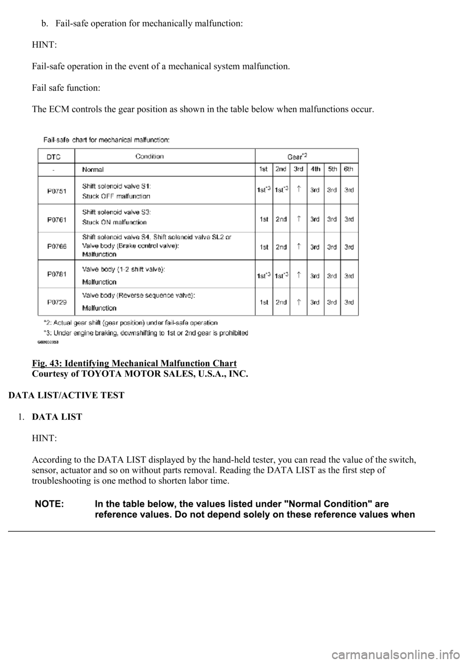
b. Fail-safe operation for mechanically malfunction:
HINT:
Fail-safe operation in the event of a mechanical system malfunction.
Fail safe function:
The ECM controls the gear position as shown in the table below when malfunctions occur.
Fig. 43: Identifying Mechanical Malfunction Chart
Courtesy of TOYOTA MOTOR SALES, U.S.A., INC.
DATA LIST/ACTIVE TEST
1.DATA LIST
HINT:
According to the DATA LIST displayed by the hand-held tester, you can read the value of the switch,
sensor, actuator and so on without parts removal. Reading the DATA LIST as the first step of
troubleshooting is one method to shorten labor time.