Page 3929 of 4500
Fig. 14: Driver Seat ECU - Data List Chart (3 Of 3)
Courtesy of TOYOTA MOTOR SALES, U.S.A., INC.
2.ACTIVE TEST
HINT:
Using the hand-held tester's ACTIVE TEST allows relay, VSV, actuator, and other items to be operated
without removing any parts. Reading the ACTIVE TEST early in troubleshooting is one way to save
Page 4009 of 4500
REPLACEMENT
HINT:
Use the same procedures for the RH side and LH side.
The procedures listed below are for the LH side.
1.REMOVE FRONT WHEELS
2.REMOVE FRONT SHOCK ABSORBER CAP LH
a. Remove the 3 nuts and front shock absorber cap LH.
Fig. 17: Removing Front Shock Absorber Cap LH
Courtesy of TOYOTA MOTOR SALES, U.S.A., INC.
3.REMOVE ABSORBER CONTROL ACTUATOR
a. Disconnect the connector.
b. Turn the absorber control actuator counter clockwise 40° and remove it in an upward direction.
Page 4010 of 4500
Fig. 18: Removing Absorber Control Actuator
Courtesy of TOYOTA MOTOR SALES, U.S.A., INC.
4.REMOVE HEIGHT CONTROL SENSOR SUB-ASSY FRONT LH
5.SEPARATE FRONT STABILIZER LINK ASSY LH
a. Support the suspension lower arm with a jack using a wood block to avoid damage.
b. Remove the nut and washer and separate the stabilizer link assy LH.
Page 4019 of 4500
Fig. 27: Installing Front Stabilizer Link Assy LH
Courtesy of TOYOTA MOTOR SALES, U.S.A., INC.
12.INSTALL HEIGHT CONTROL SENSOR SUB-ASSY FRONT LH
13.INSTALL ABSORBER CONTROL ACTUATOR
a. Check that the rod position is as shown.
Page 4020 of 4500
Fig. 28: Checking Rod Position
Courtesy of TOYOTA MOTOR SALES, U.S.A., INC.
b. Install the absorber control actuator to the pneumatic front LH w/shock absorber cylinder assy.
c. Until a response is felt, turn the absorber control actuator clockwise approx. 40°.
d. Connect the connector.
Page 4082 of 4500

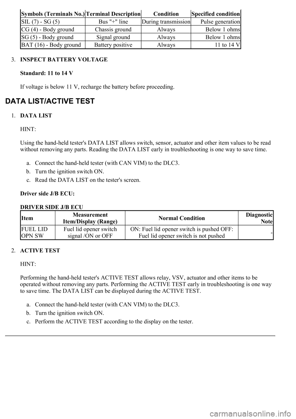
3.INSPECT BATTERY VOLTAGE
Standard: 11 to 14 V
If voltage is below 11 V, recharge the battery before proceeding.
1.DATA LIST
HINT:
Using the hand-held tester's DATA LIST allows switch, sensor, actuator and other item values to be read
without removing any parts. Reading the DATA LIST early in troubleshooting is one way to save time.
a. Connect the hand-held tester (with CAN VIM) to the DLC3.
b. Turn the ignition switch ON.
c. Read the DATA LIST on the tester's screen.
Driver side J/B ECU:
DRIVER SIDE J/B ECU
2.ACTIVE TEST
HINT:
Performing the hand-held tester's ACTIVE TEST allows relay, VSV, actuator and other items to be
operated without removing any parts. Performing the ACTIVE TEST early in troubleshooting is one way
to save time. The DATA LIST can be displayed during the ACTIVE TEST.
a. Connect the hand-held tester (with CAN VIM) to the DLC3.
b. Turn the ignition switch ON.
c. Perform the ACTIVE TEST accordin
g to the display on the tester.
Symbols (Terminals No.)Terminal DescriptionConditionSpecified condition
SIL (7) - SG (5)Bus "+" lineDuring transmissionPulse generation
CG (4) - Body groundChassis groundAlwaysBelow 1 ohms
SG (5) - Body groundSignal groundAlwaysBelow 1 ohms
BAT (16) - Body groundBattery positiveAlways11 to 14 V
ItemMeasurement
Item/Display (Range)Normal ConditionDiagnostic
Note
FUEL LID
OPN SWFuel lid opener switch
signal /ON or OFFON: Fuel lid opener switch is pushed OFF:
Fuel lid opener switch is not pushed-
Page 4402 of 4500
Fig. 3: Inspecting Intake Air Control Function
Courtesy of TOYOTA MOTOR SALES, U.S.A., INC.
a. Remove the V-bank cover.
b. Connect the hand-held tester (with CAN VIM) to the DLC3.
c. Perform the ACTIVE TEST, and then check that the actuator rod operates.
d. Start the engine.
e. Check that the VSV for IAC valve in ON (seal) under these conditions.
Depressing the accelerator pedal to a throttle valve opening angle of 60 degrees.
Racing the engine above 4,700 rpm.
f. Check that the VSV for IAC valve is OFF (vent) under these conditions.
The engine is idling.
Releasing the accelerator pedal while under the 2 conditions in step (e).
If the result is not as specified, inspect the IAC valve, vacuum tank and VSV for normal operation.
Replace malfunctioning parts as necessary.
INSPECTION
1.INSPECT INTAKE AIR CONTROL VALVE ACTUATOR
a. Connect the MITYVAC (han
d-held vacuum pump) to the actuator.
Page 4403 of 4500
b. Apply a vacuum of 39.9 kPa (300 mmHg, 11.8 in.Hg) to the actuator and check that the actuator
rod moves.
c. One minute after applying the vacuum, check that the rod's position is the same as in step (a).
If the result is not as specified, replace the IAC valve actuator.
Fig. 4: Inspect Intake Air Control Valve Actuator
Courtesy of TOYOTA MOTOR SALES, U.S.A., INC.
2.INSPECT VACUUM TANK
a. Connect the MITYVAC (hand-held vacuum pump) to port A.
b. Apply a vacuum of 66.7 kPa (500 mmHg, 20 in.Hg) to the vacuum tank.
c. One minute after applying the vacuum, check that the pressure does not change.
If the result is not as specified, replace the vacuum control valve set.