Page 2873 of 4500
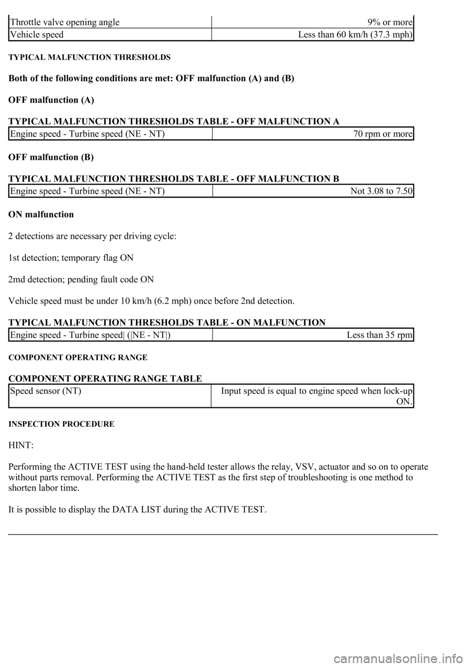
TYPICAL MALFUNCTION THRESHOLDS
Both of the following conditions are met: OFF malfunction (A) and (B)
OFF malfunction (A)
TYPICAL MALFUNCTION THRESHOLDS TABLE - OFF MALFUNCTION A
OFF malfunction (B)
TYPICAL MALFUNCTION THRESHOLDS TABLE - OFF MALFUNCTION B
ON malfunction
2 detections are necessary per driving cycle:
1st detection; temporary flag ON
2md detection; pending fault code ON
Vehicle speed must be under 10 km/h (6.2 mph) once before 2nd detection.
TYPICAL MALFUNCTION THRESHOLDS TABLE - ON MALFUNCTION
COMPONENT OPERATING RANGE
COMPONENT OPERATING RANGE TABLE
INSPECTION PROCEDURE
HINT:
Performing the ACTIVE TEST using the hand-held tester allows the relay, VSV, actuator and so on to operate
without parts removal. Performing the ACTIVE TEST as the first step of troubleshooting is one method to
shorten labor time.
It is possible to display the DATA LIST during the ACTIVE TEST.
Throttle valve opening angle9% or more
Vehicle speedLess than 60 km/h (37.3 mph)
Engine speed - Turbine speed (NE - NT)70 rpm or more
Engine speed - Turbine speed (NE - NT)Not 3.08 to 7.50
Engine speed - Turbine speed| (|NE - NT|)Less than 35 rpm
Speed sensor (NT)Input speed is equal to engine speed when lock-up
ON.
Page 2943 of 4500
ON-VEHICLE INSPECTION
1.INSPECTION THROTTLE BODY
a. Inspect the throttle control motor for operating sound.
1. Turn the ignition switch ON.
2. When turning the accelerator pedal position sensor lever, check the running sound of the
motor. The motor should be running smoothly without friction sounds.
If operation is not as specified, check the throttle control motor, wiring and ECM (see DTC P2118:
THROTTLE ACTUATOR CONTROL MOTOR CURRENT RANGE/PERFORMANCE ).
Fig. 3: Identifying Throttle Body
Courtesy of TOYOTA MOTOR SALES, U.S.A., INC.
b. Inspect the throttle position sensor.
Page 3198 of 4500
1.DATA LIST
HINT:
Using the hand-held tester's DATA LIST allows switch, sensor, actuator and other item values to be read
without removing any parts. Reading the DATA LIST early in troubleshooting is one way to save time.
a. Connect the hand-held tester to the Controller Area Network Vehicle Interface Module (CAN
VIM). Then connect the CAN VIM to the DLC3.
b. Turn the ignition switch ON.
c. Read the DATA LIST.
Steering lock ECU:
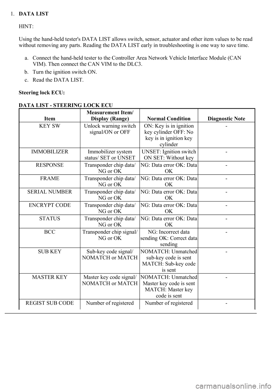
DATA LIST - STEERING LOCK ECU
Item
Measurement Item/
Display (Range)
Normal ConditionDiagnostic Note
KEY SWUnlock warning switch
signal/ON or OFFON: Key is in ignition
key cylinder OFF: No
key is in ignition key
cylinder-
IMMOBILIZERImmobilizer system
status/ SET or UNSETUNSET: Ignition switch
ON SET: Without key-
RESPONSETransponder chip data/
NG or OKNG: Data error OK: Data
OK-
FRAMETransponder chip data/
NG or OKNG: Data error OK: Data
OK-
SERIAL NUMBERTransponder chip data/
NG or OKNG: Data error OK: Data
OK-
ENCRYPT CODETransponder chip data/
NG or OKNG: Data error OK: Data
OK-
STATUSTransponder chip data/
NG or OKNG: Data error OK: Data
OK-
BCCTransponder chip signal/
NG or OKNG: Incorrect data
sending OK: Correct data
sending-
SUB KEYSub-key code signal/
NOMATCH or MATCHNOMATCH: Unmatched
sub-key code is sent
MATCH: Sub-key code
is sent-
MASTER KEYMaster key code signal/
NOMATCH or MATCHNOMATCH: Unmatched
Master key code is sent
MATCH: Master key
code is sent-
REGIST SUB CODENumber of registered Number of registered -
Page 3199 of 4500
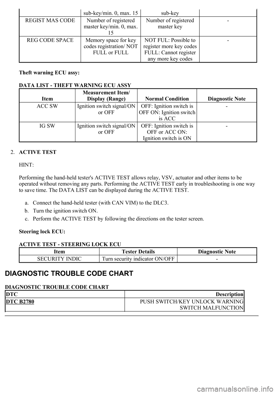
Theft warning ECU assy:
DATA LIST - THEFT WARNING ECU ASSY
2.ACTIVE TEST
HINT:
Performing the hand-held tester's ACTIVE TEST allows relay, VSV, actuator and other items to be
operated without removing any parts. Performing the ACTIVE TEST early in troubleshooting is one way
to save time. The DATA LIST can be displayed during the ACTIVE TEST.
a. Connect the hand-held tester (with CAN VIM) to the DLC3.
b. Turn the ignition switch ON.
c. Perform the ACTIVE TEST by following the directions on the tester screen.
Steering lock ECU:
ACTIVE TEST - STEERING LOCK ECU
DIAGNOSTIC TROUBLE CODE CHART
sub-key/min. 0, max. 15sub-key
REGIST MAS CODENumber of registered
master key/min. 0, max.
15Number of registered
master key-
REG CODE SPACEMemory space for key
codes registration/ NOT
FULL or FULLNOT FUL: Possible to
register more key codes
FULL: Cannot register
any more key codes-
Item
Measurement Item/
Display (Range)
Normal ConditionDiagnostic Note
ACC SWIgnition switch signal/ON
or OFFOFF: Ignition switch is
OFF ON: Ignition switch
is ACC-
IG SWIgnition switch signal/ON
or OFFOFF: Ignition switch is
OFF or ACC ON:
Ignition switch is ON-
ItemTester DetailsDiagnostic Note
SECURITY INDICTurn security indicator ON/OFF-
DTCDescription
DTC B2780PUSH SWITCH/KEY UNLOCK WARNING
SWITCH MALFUNCTION
Page 3253 of 4500
1.DATA LIST
HINT:
Using the hand-held tester's DATA LIST allows switch, sensor, actuator and other item values to be read
without removing any parts. Reading the DATA LIST early in troubleshooting is one way to save time.
a. Connect the hand-held tester to the Controller Area Network Vehicle Interface Module (CAN
VIM). Then connect the CAN VIM to the DLC3.
b. Turn the ignition switch ON.
c. Read the DATA LIST.
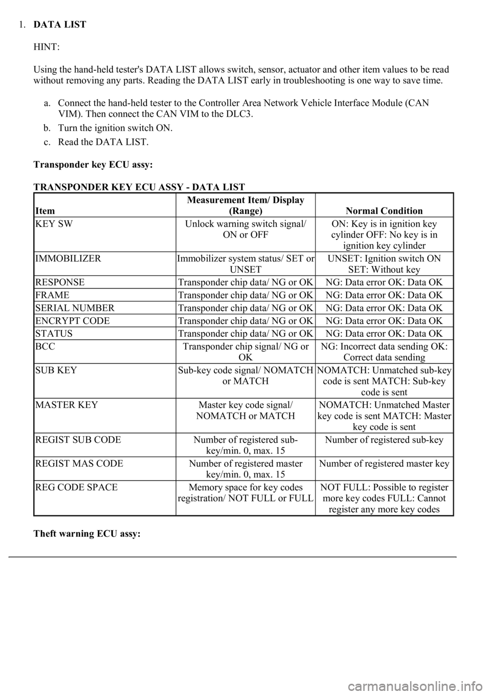
Transponder key ECU assy:
TRANSPONDER KEY ECU ASSY - DATA LIST
Theft warning ECU assy:
Item
Measurement Item/ Display
(Range)
Normal Condition
KEY SWUnlock warning switch signal/
ON or OFFON: Key is in ignition key
cylinder OFF: No key is in
ignition key cylinder
IMMOBILIZERImmobilizer system status/ SET or
UNSETUNSET: Ignition switch ON
SET: Without key
RESPONSETransponder chip data/ NG or OKNG: Data error OK: Data OK
FRAMETransponder chip data/ NG or OKNG: Data error OK: Data OK
SERIAL NUMBERTransponder chip data/ NG or OKNG: Data error OK: Data OK
ENCRYPT CODETransponder chip data/ NG or OKNG: Data error OK: Data OK
STATUSTransponder chip data/ NG or OKNG: Data error OK: Data OK
BCCTransponder chip signal/ NG or
OKNG: Incorrect data sending OK:
Correct data sending
SUB KEYSub-key code signal/ NOMATCH
or MATCHNOMATCH: Unmatched sub-key
code is sent MATCH: Sub-key
code is sent
MASTER KEYMaster key code signal/
NOMATCH or MATCHNOMATCH: Unmatched Master
key code is sent MATCH: Master
key code is sent
REGIST SUB CODENumber of registered sub-
key/min. 0, max. 15Number of registered sub-key
REGIST MAS CODENumber of registered master
key/min. 0, max. 15Number of registered master key
REG CODE SPACEMemory space for key codes
registration/ NOT FULL or FULLNOT FULL: Possible to register
more key codes FULL: Cannot
register any more key codes
Page 3254 of 4500
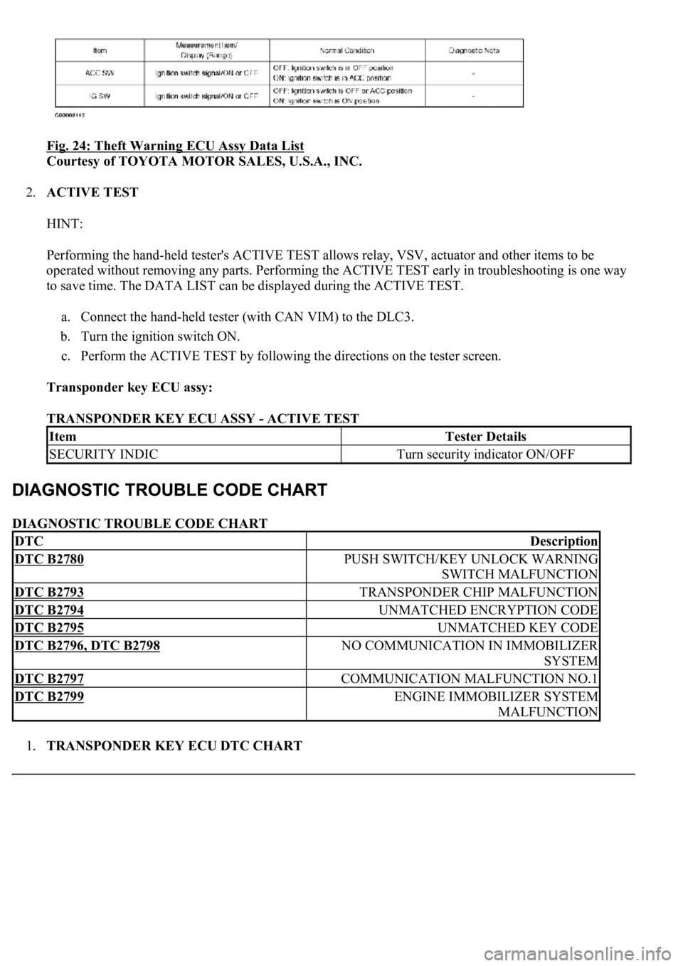
Fig. 24: Theft Warning ECU Assy Data List
Courtesy of TOYOTA MOTOR SALES, U.S.A., INC.
2.ACTIVE TEST
HINT:
Performing the hand-held tester's ACTIVE TEST allows relay, VSV, actuator and other items to be
operated without removing any parts. Performing the ACTIVE TEST early in troubleshooting is one way
to save time. The DATA LIST can be displayed during the ACTIVE TEST.
a. Connect the hand-held tester (with CAN VIM) to the DLC3.
b. Turn the ignition switch ON.
c. Perform the ACTIVE TEST by following the directions on the tester screen.
Transponder key ECU assy:
TRANSPONDER KEY ECU ASSY - ACTIVE TEST
DIAGNOSTIC TROUBLE CODE CHART
1.TRANSPONDER KEY ECU DTC CHART
ItemTester Details
SECURITY INDICTurn security indicator ON/OFF
DTCDescription
DTC B2780PUSH SWITCH/KEY UNLOCK WARNING
SWITCH MALFUNCTION
DTC B2793TRANSPONDER CHIP MALFUNCTION
DTC B2794UNMATCHED ENCRYPTION CODE
DTC B2795UNMATCHED KEY CODE
DTC B2796, DTC B2798NO COMMUNICATION IN IMMOBILIZER
SYSTEM
DTC B2797COMMUNICATION MALFUNCTION NO.1
DTC B2799ENGINE IMMOBILIZER SYSTEM
MALFUNCTION
Page 3788 of 4500
Fig. 5: Removing Front Bumper Cover
Courtesy of TOYOTA MOTOR SALES, U.S.A., INC.
6.REMOVE HEADLAMP CLEANER (FROM MOTOR TO JOINT) HOSE (W/ HEADLAMP
CLEANER)
a. Disconnect the cleaner hose joint from the actuator.
HINT:
Be careful when removing the cleaner hose from the actuator, because washer fluid will spill.
b. Disconnect the cleaner hose from the bumper cover.
7.REMOVE FRONT BUMPER ENERGY ABSORBER
8.REMOVE RADIATOR SUPPORT REINFORCEMENT LOWER
a. Remove the 2 bolts.
b. Unlock the 2 claws and partially remove the reinforcement lower by angling it towards yourself.
HINT:
It is not necessar
y to fully remove the reinforcement lower completely. Partially remove it so that the
Page 3791 of 4500
Fig. 8: Removing Headlamp Cleaner Washer Nozzle (W/Headlamp Cleaner)
Courtesy of TOYOTA MOTOR SALES, U.S.A., INC.
14.REMOVE HEADLAMP WASHER ACTUATOR SUB-ASSY LH (W/ HEADLAMP CLEANER)
a. Remove the screw and actuator.
15.REMOVE HEADLAMP WASHER ACTUATOR SUB-ASSY RH (W/ HEADLAMP CLEANER)
a. Remove the screw and actuator.
16.REMOVE ULTRASONIC SENSOR NO. 1 (w/ CLEARANCE SONAR SYSTEM)
a. Using a screwdriver, remove the retainer and sensor.
HINT:
Tape the screwdriver tip before use.
17.REMOVE FRONT BUMPER EXTENSION MOUNTING BRACKET
a. Remove the 2 screws and mounting bracket.
18.REMOVE FRONT BUMPER SIDE RETAINER LH
a. Use a drill that has a tip of less than phis 4 mm (0.16 in.).
b. Tape the drill tip as shown in Fig. 9.