Page 1776 of 4500
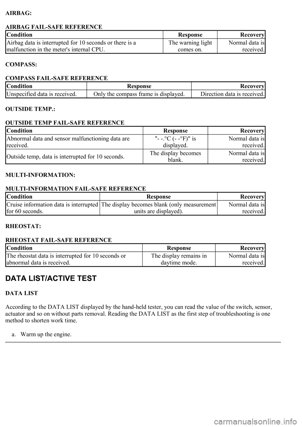
AIRBAG:
AIRBAG FAIL-SAFE REFERENCE
COMPASS:
COMPASS FAIL-SAFE REFERENCE
OUTSIDE TEMP.:
OUTSIDE TEMP FAIL-SAFE REFERENCE
MULTI-INFORMATION:
MULTI-INFORMATION FAIL-SAFE REFERENCE
RHEOSTAT:
RHEOSTAT FAIL-SAFE REFERENCE
DATA LIST
According to the DATA LIST displayed by the hand-held tester, you can read the value of the switch, sensor,
actuator and so on without parts removal. Reading the DATA LIST as the first step of troubleshooting is one
method to shorten work time.
a. Warm up the en
gine.
ConditionResponseRecovery
Airbag data is interrupted for 10 seconds or there is a
malfunction in the meter's internal CPU.The warning light
comes on.Normal data is
received.
ConditionResponseRecovery
Unspecified data is received.Only the compass frame is displayed.Direction data is received.
ConditionResponseRecovery
Abnormal data and sensor malfunctioning data are
received."- -.°C (- -°F)" is
displayed.Normal data is
received.
Outside temp, data is interrupted for 10 seconds.The display becomes
blank.Normal data is
received.
ConditionResponseRecovery
Cruise information data is interrupted
for 60 seconds.The display becomes blank (only measurement
units are displayed).Normal data is
received.
ConditionResponseRecovery
<0037004b004800030055004b004800520056005700440057000300470044005700440003004c00560003004c005100570048005500550058005300570048004700030049005200550003001400130003005600480046005200510047005600030052005500
03[
abnormal data is received.The display remains in
daytime mode.Normal data is
received.
Page 1789 of 4500
5.CHECK HARNESS AND CONNECTOR (ABS & TRACTION ACTUATOR ASSY (VSC) -
COMBINATION METER ASSY) (SEE HOW TO PROCEED WITH TROUBLESHOOTING
)
a. Disconnect the C12 and S42 connectors.
b. Measure the resistance according to the value (s) in the table below.
Standard
C12 AND S42 CONNECTORS RESISTANCE SPECIFICATIONS
Tester ConnectionConditionSpecified Condition
C12-18 - S42-12AlwaysBelow 1 ohms
C12-18 - Body groundAlways10 kohms or higher
Page 1791 of 4500
Fig. 48: Identifying C12 And S42 Connectors
Courtesy of TOYOTA MOTOR SALES, U.S.A., INC.
NG: REPAIR OR REPLACE HARNESS AND CONNECTOR
OK: GO TO NEXT STEP
6.INSPECT ABS & TRACTION ACTUATOR ASSY (VSC)
a. Disconnect the S42 connector.
b. Measure the voltage according to the value (s) in the table below.
Standard
S42 connector VOLTAGE SPECIFICATIONS
NG: REPLACE COMBINATION METER ASSY (SEE OVERHAUL
)
Fig. 49: Identifying S42 Connector Terminals
Courtesy of TOYOTA MOTOR SALES, U.S.A., INC.
OK: GO TO BRAKE CONTROL SYSTEM (SEE HOW TO PROCEED WITH
TROUBLESHOOTING )
Tester ConnectionConditionSpecified Condition
S42-12 - Body groundIgnition switch ON10 to 14 V
Page 1904 of 4500
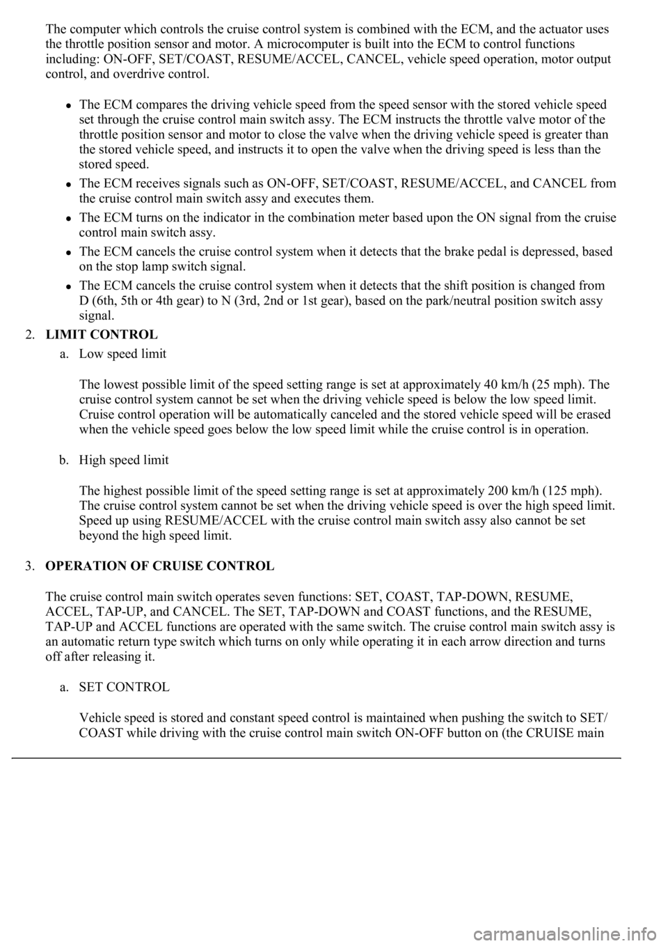
The computer which controls the cruise control system is combined with the ECM, and the actuator uses
the throttle position sensor and motor. A microcomputer is built into the ECM to control functions
including: ON-OFF, SET/COAST, RESUME/ACCEL, CANCEL, vehicle speed operation, motor output
control, and overdrive control.
The ECM compares the driving vehicle speed from the speed sensor with the stored vehicle speed
set through the cruise control main switch assy. The ECM instructs the throttle valve motor of the
throttle position sensor and motor to close the valve when the driving vehicle speed is greater than
the stored vehicle speed, and instructs it to open the valve when the driving speed is less than the
stored speed.
The ECM receives signals such as ON-OFF, SET/COAST, RESUME/ACCEL, and CANCEL from
the cruise control main switch assy and executes them.
The ECM turns on the indicator in the combination meter based upon the ON signal from the cruise
control main switch assy.
The ECM cancels the cruise control system when it detects that the brake pedal is depressed, based
on the stop lamp switch signal.
The ECM cancels the cruise control system when it detects that the shift position is changed from
D (6th, 5th or 4th gear) to N (3rd, 2nd or 1st gear), based on the park/neutral position switch assy
signal.
2.LIMIT CONTROL
a. Low speed limit
The lowest possible limit of the speed setting range is set at approximately 40 km/h (25 mph). The
cruise control system cannot be set when the driving vehicle speed is below the low speed limit.
Cruise control operation will be automatically canceled and the stored vehicle speed will be erased
when the vehicle speed goes below the low speed limit while the cruise control is in operation.
b. High speed limit
The highest possible limit of the speed setting range is set at approximately 200 km/h (125 mph).
The cruise control system cannot be set when the driving vehicle speed is over the high speed limit.
Speed up using RESUME/ACCEL with the cruise control main switch assy also cannot be set
beyond the high speed limit.
3.OPERATION OF CRUISE CONTROL
The cruise control main switch operates seven functions: SET, COAST, TAP-DOWN, RESUME,
ACCEL, TAP-UP, and CANCEL. The SET, TAP-DOWN and COAST functions, and the RESUME,
TAP-UP and ACCEL functions are operated with the same switch. The cruise control main switch assy is
an automatic return type switch which turns on only while operating it in each arrow direction and turns
off after releasing it.
a. SET CONTROL
Vehicle speed is stored and constant speed control is maintained when pushing the switch to SET/
COAST while drivin
g with the cruise control main switch ON-OFF button on (the CRUISE main
Page 1921 of 4500
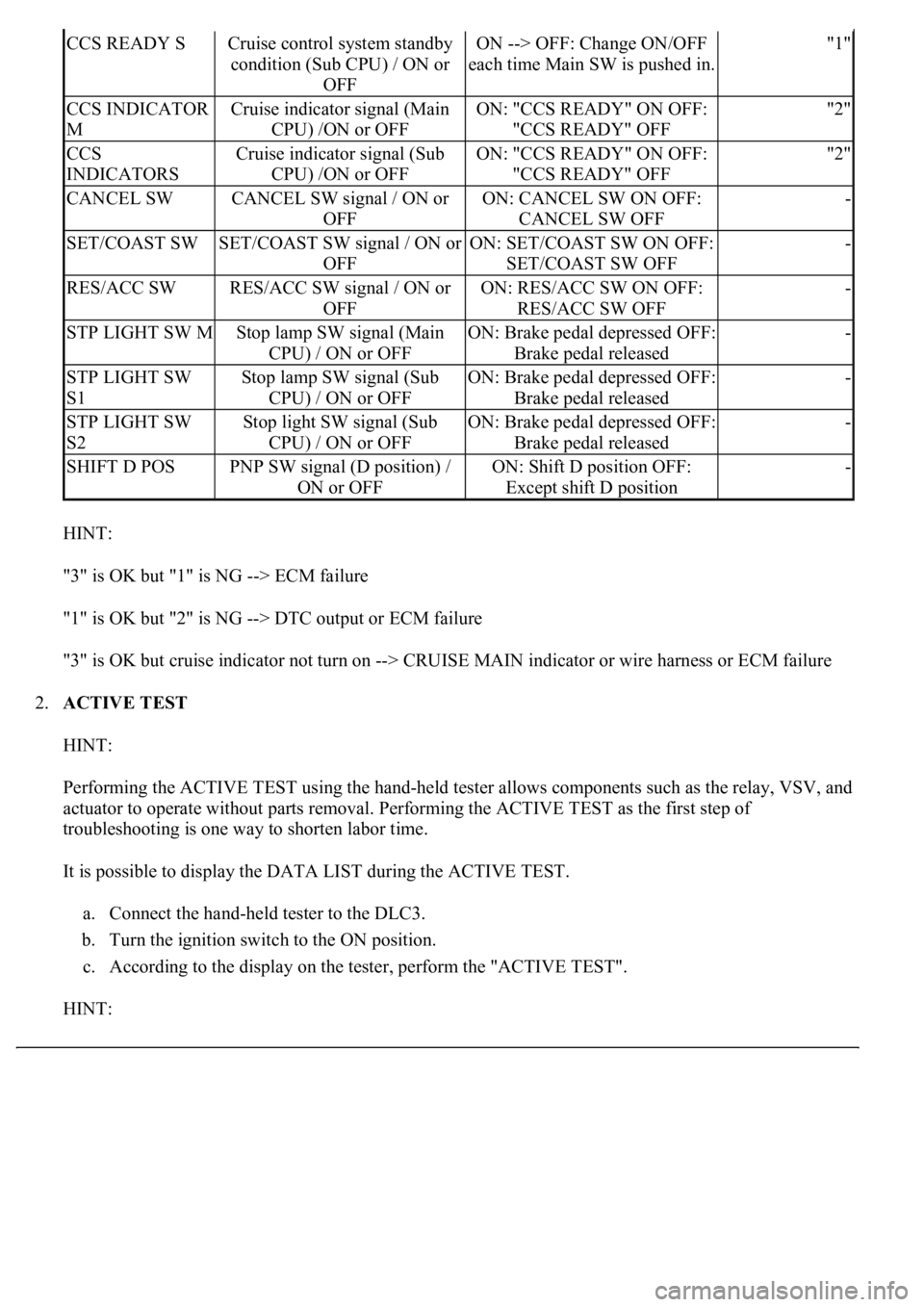
HINT:
"3" is OK but "1" is NG --> ECM failure
"1" is OK but "2" is NG --> DTC output or ECM failure
"3" is OK but cruise indicator not turn on --> CRUISE MAIN indicator or wire harness or ECM failure
2.ACTIVE TEST
HINT:
Performing the ACTIVE TEST using the hand-held tester allows components such as the relay, VSV, and
actuator to operate without parts removal. Performing the ACTIVE TEST as the first step of
troubleshooting is one way to shorten labor time.
It is possible to display the DATA LIST during the ACTIVE TEST.
a. Connect the hand-held tester to the DLC3.
b. Turn the ignition switch to the ON position.
c. According to the display on the tester, perform the "ACTIVE TEST".
HINT:
CCS READY SCruise control system standby
condition (Sub CPU) / ON or
OFFON --> OFF: Change ON/OFF
each time Main SW is pushed in."1"
CCS INDICATOR
MCruise indicator signal (Main
CPU) /ON or OFFON: "CCS READY" ON OFF:
"CCS READY" OFF"2"
CCS
INDICATORSCruise indicator signal (Sub
CPU) /ON or OFFON: "CCS READY" ON OFF:
"CCS READY" OFF"2"
CANCEL SWCANCEL SW signal / ON or
OFFON: CANCEL SW ON OFF:
CANCEL SW OFF-
SET/COAST SWSET/COAST SW signal / ON or
OFFON: SET/COAST SW ON OFF:
SET/COAST SW OFF-
RES/ACC SWRES/ACC SW signal / ON or
OFFON: RES/ACC SW ON OFF:
RES/ACC SW OFF-
STP LIGHT SW MStop lamp SW signal (Main
CPU) / ON or OFFON: Brake pedal depressed OFF:
Brake pedal released-
STP LIGHT SW
S1Stop lamp SW signal (Sub
CPU) / ON or OFFON: Brake pedal depressed OFF:
Brake pedal released-
STP LIGHT SW
S2Stop light SW signal (Sub
CPU) / ON or OFFON: Brake pedal depressed OFF:
Brake pedal released-
SHIFT D POSPNP SW signal (D position) /
ON or OFFON: Shift D position OFF:
Except shift D position-
Page 1997 of 4500
Fig. 7: Connecting Hand-Held Tester To DLC3
Courtesy of TOYOTA MOTOR SALES, U.S.A., INC.
3.INSPECT BATTERY VOLTAGE
Standard: 11 to 14 V
If voltage is below 11 V, recharge the battery before proceeding.
1.ACTIVE TEST
HINT:
Performing the hand-held tester's ACTIVE TEST allows relay, VSV, actuator and other items to be
operated without removing any parts. Performing the ACTIVE TEST early in troubleshooting is one way
to save time.
a. Connect the hand-held tester (with CAN VIM) to the DLC3.
b. Turn the ignition switch ON.
Page 2198 of 4500
Courtesy of TOYOTA MOTOR SALES, U.S.A., INC.
2.CLEAR DTC
a. Connect the hand-held tester to the Controller Area Network Vehicle Interface Module (CAN
VIM). Then connect the CAN VIM to the DLC3.
b. Turn the ignition switch ON.
c. Erase the DTCs by following the prompts on the tester screen.
HINT:
Refer to the hand-held tester operator's manual for further details.
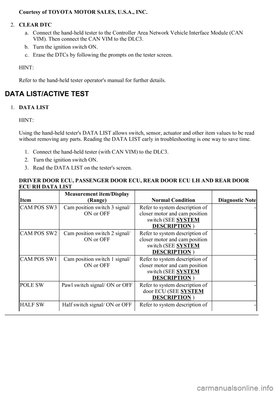
1.DATA LIST
HINT:
Using the hand-held tester's DATA LIST allows switch, sensor, actuator and other item values to be read
without removing any parts. Reading the DATA LIST early in troubleshooting is one way to save time.
1. Connect the hand-held tester (with CAN VIM) to the DLC3.
2. Turn the ignition switch ON.
3. Read the DATA LIST on the tester's screen.
DRIVER DOOR ECU, PASSENGER DOOR ECU, REAR DOOR ECU LH AND REAR DOOR
ECU RH DATA LIST
Item
Measurement item/Display
(Range)
Normal ConditionDiagnostic Note
CAM POS SW3Cam position switch 3 signal/
ON or OFFRefer to system description of
closer motor and cam position
switch (SEE SYSTEM
DESCRIPTION )
-
CAM POS SW2Cam position switch 2 signal/
ON or OFFRefer to system description of
closer motor and cam position
switch (SEE SYSTEM
DESCRIPTION )
-
CAM POS SW1Cam position switch 1 signal/
ON or OFFRefer to system description of
closer motor and cam position
switch (SEE SYSTEM
DESCRIPTION )
-
POLE SWPawl switch signal/ ON or OFFRefer to system description of
door ECU (SEE SYSTEM
DESCRIPTION )
-
HALF SWHalf switch signal/ ON or OFFRefer to system description of -
Page 2418 of 4500
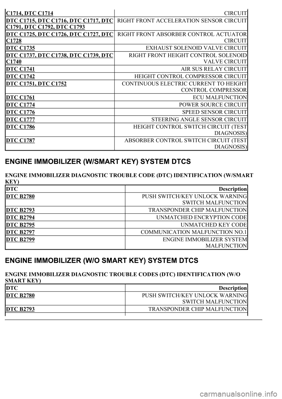
ENGINE IMMOBILIZER DIAGNOSTIC TROUBLE CODE (DTC) IDENTIFICATION (W/SMART
KEY)
ENGINE IMMOBILIZER DIAGNOSTIC TROUBLE CODES (DTC) IDENTIFICATION (W/O
SMART KEY)
C1714, DTC C1714 CIRCUIT
DTC C1715, DTC C1716, DTC C1717, DTC
C1791, DTC C1792, DTC C1793
RIGHT FRONT ACCELERATION SENSOR CIRCUIT
DTC C1725, DTC C1726, DTC C1727, DTC
C1728
RIGHT FRONT ABSORBER CONTROL ACTUATOR
CIRCUIT
DTC C1735 EXHAUST SOLENOID VALVE CIRCUIT
DTC C1737, DTC C1738, DTC C1739, DTC
C1740
RIGHT FRONT HEIGHT CONTROL SOLENOID
VALVE CIRCUIT
DTC C1741 AIR SUS RELAY CIRCUIT
DTC C1742 HEIGHT CONTROL COMPRESSOR CIRCUIT
DTC C1751, DTC C1752 CONTINUOUS ELECTRIC CURRENT TO HEIGHT
CONTROL COMPRESSOR
DTC C1761 ECU MALFUNCTION
DTC C1774 POWER SOURCE CIRCUIT
DTC C1776 SPEED SENSOR CIRCUIT
DTC C1777 STEERING ANGLE SENSOR CIRCUIT
DTC C1786 HEIGHT CONTROL SWITCH CIRCUIT (TEST
DIAGNOSIS)
DTC C1787 ABSORBER CONTROL SWITCH CIRCUIT (TEST
DIAGNOSIS)
DTCDescription
DTC B2780 PUSH SWITCH/KEY UNLOCK WARNING
SWITCH MALFUNCTION
DTC B2793 TRANSPONDER CHIP MALFUNCTION
DTC B2794 UNMATCHED ENCRYPTION CODE
DTC B2795 UNMATCHED KEY CODE
DTC B2797 COMMUNICATION MALFUNCTION NO.1
DTC B2799 ENGINE IMMOBILIZER SYSTEM
MALFUNCTION
DTCDescription
DTC B2780 PUSH SWITCH/KEY UNLOCK WARNING
SWITCH MALFUNCTION
DTC B2793 TRANSPONDER CHIP MALFUNCTION