Page 3285 of 4500
Fig. 5: Checking Cylinder'S Compression Pressure
Courtesy of TOYOTA MOTOR SALES, U.S.A., INC.
HINT:
If adding oil increases the compression, the piston rings and/or cylinder bore may be worn or
damaged.
If pressure stays low, a valve may be stuck or seated improperly, or there may be leakage in
the gasket.
i. Connect the 8 injector connectors.
j. Install the spark plugs.
k. Install the 8 ignition coils.
l. Install the oil level gauge guide.
m. Connect the throttle control motor connector.
n. Install the air cleaner inlet and intake air pipe.
o. Install the V-bank cover.
10.INSPECT CO/HC
a. Start the engine.
b. Rev the engine at 2,500 rpm for approximately 180 seconds.
Page 3286 of 4500

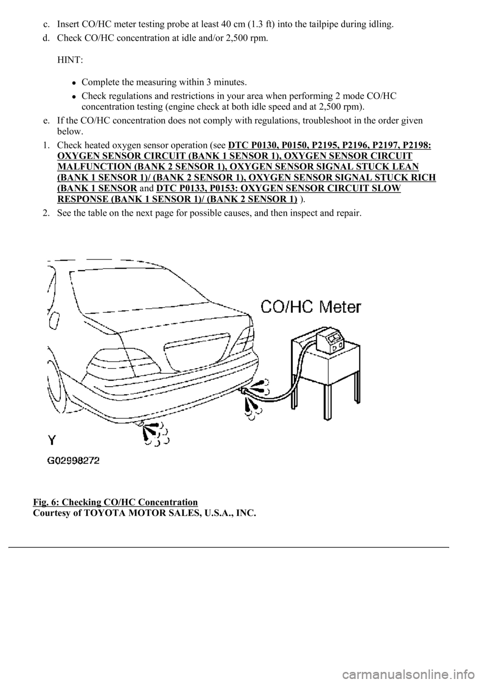
c. Insert CO/HC meter testing probe at least 40 cm (1.3 ft) into the tailpipe during idling.
d. Check CO/HC concentration at idle and/or 2,500 rpm.
HINT:
Complete the measuring within 3 minutes.
Check regulations and restrictions in your area when performing 2 mode CO/HC
concentration testing (engine check at both idle speed and at 2,500 rpm).
e. If the CO/HC concentration does not comply with regulations, troubleshoot in the order given
below.
1. Check heated oxygen sensor operation (see DTC P0130, P0150, P2195, P2196, P2197, P2198:
OXYGEN SENSOR CIRCUIT (BANK 1 SENSOR 1), OXYGEN SENSOR CIRCUIT
MALFUNCTION (BANK 2 SENSOR 1), OXYGEN SENSOR SIGNAL STUCK LEAN
(BANK 1 SENSOR 1)/ (BANK 2 SENSOR 1), OXYGEN SENSOR SIGNAL STUCK RICH
(BANK 1 SENSOR and DTC P0133, P0153: OXYGEN SENSOR CIRCUIT SLOW
RESPONSE (BANK 1 SENSOR 1)/ (BANK 2 SENSOR 1) ).
2. See the table on the next page for possible causes, and then inspect and repair.
Fig. 6: Checking CO/HC Concentration
Courtesy of TOYOTA MOTOR SALES, U.S.A., INC.
Page 3350 of 4500
Fig. 70: Identifying Painted Mark
Courtesy of TOYOTA MOTOR SALES, U.S.A., INC.
107.INSTALL AUTOMATIC TRANSMISSION ASSY
a. Check the torque converter clutch installation (see INSPECTION
).
b. Attach the transmission to the engine.
c. Install the ground strap and 10 bolts.
Torque:
72 N.m (734 kgf.cm, 53 ft.lbf) for 17 mm head bolt A
37 N.m (377 kgf.cm, 27 ft.lbf) for 14 mm head bolt B
Page 3361 of 4500

140.INSTALL ENGINE UNDER COVER NO.2
141.INSTALL ENGINE UNDER COVER NO.1
142.INSTALL FRONT WHEEL
143.INSTALL AIR CLEANER ASSY
144.INSTALL INTAKE AIR CONNECTOR PIPE
145.INSTALL AIR CLEANER INLET NO.1
146.INSTALL V-BANK COVER
147.INSTALL HOOD SUB-ASSY (See ADJUSTMENT
and OVERHAUL )
148.CONNECT BATTERY NEGATIVE TERMINAL
149.ADD AUTOMATIC TRANSMISSION FLUID
150.ADD ENGINE COOLANT (See REPLACEMENT
)
151.ADD ENGINE OIL (See ON
-VEHICLE INSPECTION )
152.ADD POWER STEERING FLUID
153.BLEED POWER STEERING FLUID
154.INSPECT AUTOMATIC TRANSMISSION FLUID (See ADJUSTMENT
)
155.INSPECT ENGINE OIL LEAKS
156.CHECK FOR ENGINE COOLANT LEAKS
157.INSPECT FOR FUEL LEAKS
158.CHECK FOR EXHAUST GAS LEAKS
159.INSPECT AND ADJUST FRONT WHEEL ALIGNMENT
160.INSPECT IGNITION TIMING
161.INSPECT ENGINE IDLE SPEED
162.INSPECT CO/HC
163.ADJUST ENGINE (See INSPECTION
)
164.CHECK ABS SPEED SENSOR SIGNAL (See TEST MODE PROCEDURE
)
OVERHAUL
1.REMOVE SPARK PLUG
2.REMOVE OIL FILLER CAP SUB-ASSY
3.REMOVE CYLINDER HEAD COVER SUB-ASSY LH
a. Remove the 9 bolts, 9 seal washers, cylinder head cover and gasket.
4.REMOVE CYLINDER HEAD COVER SUB-ASSY
a. Remove the 9 bolts, 9 seal washers, c
ylinder head cover and gasket.
Page 3496 of 4500
46.INSTALL OIL COOLER OUTLET TUBE NO.1
47.INSTALL OIL COOLER INLET TUBE NO.
48.INSTALL AIR CLEANER INLET NO.1
Torque: 5.0 N.m (51 kgf.cm, 44 in.lbf)
49.INSTALL INTAKE AIR CONNECTOR PIPE
Torque: 5.0 N.m (51 kgf.cm, 44 in.lbf)
50.INSTALL V-BANK COVER
Torque: 5.0 N.m (51 kgf.cm, 44 in.lbf)
51.REFILL ENGINE COOLANT (See REPLACEMENT
)
52.CHECK FOR ENGINE COOLANT LEAKS (See ON
-VEHICLE INSPECTION )
53.INSTALL ENGINE UNDER COVER NO.1
54.CONNECT BATTERY NEGATIVE TERMINAL
REPLACEMENT
1.REMOVE TIMING BELT (See REPLACEMENT
)
2.REMOVE CYLINDER HEAD COVER SUB-ASSY (See REPLACEMENT
)
3.PISTON & VALVE BREAK PREVENT WORK
a. Turn the crankshaft timing pulley counterclockwise by 45° and match the cut part with the
illustrated position.
HINT:
When the No. 1 cylinder is positioned at 45° BTDC, the valve and piston do not interfere with each other
even when the valve is fully open.
Page 3562 of 4500
Fig. 278: Tightening Cylinder Head Bolts
Courtesy of TOYOTA MOTOR SALES, U.S.A., INC.
18.INSTALL CYLINDER HEAD SUB-ASSY
a. Check that the cut part of the crankshaft timing pulley is in the position shown in the illustration,
and that the piston is below the TDC of compression.
b. Install the cylinder head together with the manifold RH to the cylinder block.
c. Apply a light coat of engine oil on the threads and under the head of the cylinder head bolts.
d. Put the washer on the bolt, and insert the bolt with washer into the cylinder head.
Page 3575 of 4500
Fig. 291: Removing Cylinder Head Gasket No.2
Courtesy of TOYOTA MOTOR SALES, U.S.A., INC.
17.INSTALL CYLINDER HEAD GASKET NO.2
a. Place a new cylinder head gasket in position on the cylinder block.
b. The rear side of the cylinder head gasket has marks so that the RH and LH banks can be
distinguished. A "3L" mark is on the LH bank's gasket.
18.INSTALL CYLINDER HEAD LH
a. Check that the cut part of the crankshaft timing pulley is in the position shown in the illustration,
and that the piston is below the TDC of compression.
b. Install the cylinder head together with the manifold RH to the cylinder block.
c. Apply a light coat of engine oil on the threads and under the head of the cylinder head bolts.
d. Put the washer on the bolt, and insert the bolt with washer into the c
ylinder head.
Page 3589 of 4500
Fig. 305: Removing Drive Plate And Ring Gear And The Front Spacer
Courtesy of TOYOTA MOTOR SALES, U.S.A., INC.
b. Remove the 8 mounting bolts, the rear spacer, the drive plate and ring gear and the front spacer.
3.REMOVE ENGINE REAR OIL SEAL
a. Using a knife, cut the oil seal lip.
b. Using a screwdriver with its tip taped, pry out the oil seal.
c. After the removal, check if the crankshaft is not damaged.