Page 3267 of 4500

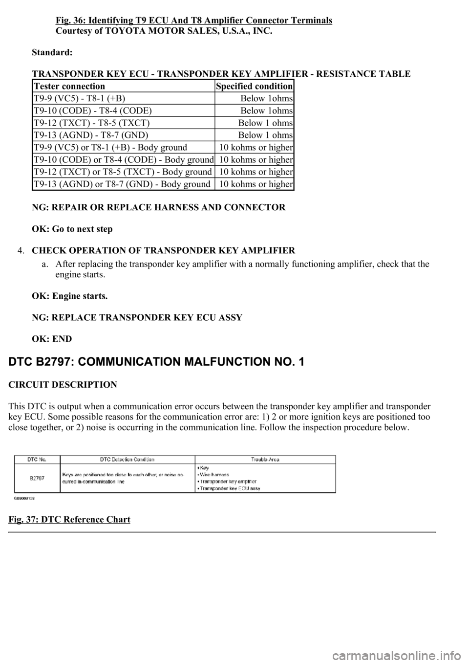
Fig. 36: Identifying T9 ECU And T8 Amplifier Connector Terminals
Courtesy of TOYOTA MOTOR SALES, U.S.A., INC.
Standard:
TRANSPONDER KEY ECU - TRANSPONDER KEY AMPLIFIER - RESISTANCE TABLE
NG: REPAIR OR REPLACE HARNESS AND CONNECTOR
OK: Go to next step
4.CHECK OPERATION OF TRANSPONDER KEY AMPLIFIER
a. After replacing the transponder key amplifier with a normally functioning amplifier, check that the
engine starts.
OK: Engine starts.
NG: REPLACE TRANSPONDER KEY ECU ASSY
OK: END
CIRCUIT DESCRIPTION
This DTC is output when a communication error occurs between the transponder key amplifier and transponder
key ECU. Some possible reasons for the communication error are: 1) 2 or more ignition keys are positioned too
close together, or 2) noise is occurring in the communication line. Follow the inspection procedure below.
Fig. 37: DTC Reference Chart
Tester connectionSpecified condition
T9-9 (VC5) - T8-1 (+B)Below 1ohms
T9-10 (CODE) - T8-4 (CODE)Below 1ohms
T9-12 (TXCT) - T8-5 (TXCT)Below 1 ohms
T9-13 (AGND) - T8-7 (GND)Below 1 ohms
T9-9 (VC5) or T8-1 (+B) - Body ground10 kohms or higher
T9-10 (CODE) or T8-4 (CODE) - Body ground10 kohms or higher
T9-12 (TXCT) or T8-5 (TXCT) - Body ground10 kohms or higher
T9-13 (AGND) or T8-7 (GND) - Body ground10 kohms or higher
Page 3273 of 4500

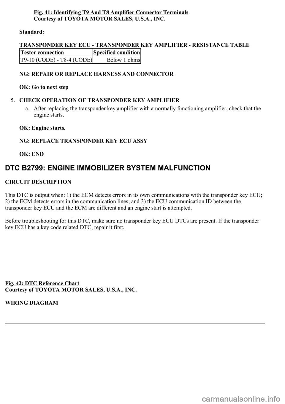
Fig. 41: Identifying T9 And T8 Amplifier Connector Terminals
Courtesy of TOYOTA MOTOR SALES, U.S.A., INC.
Standard:
TRANSPONDER KEY ECU - TRANSPONDER KEY AMPLIFIER - RESISTANCE TABLE
NG: REPAIR OR REPLACE HARNESS AND CONNECTOR
OK: Go to next step
5.CHECK OPERATION OF TRANSPONDER KEY AMPLIFIER
a. After replacing the transponder key amplifier with a normally functioning amplifier, check that the
engine starts.
OK: Engine starts.
NG: REPLACE TRANSPONDER KEY ECU ASSY
OK: END
CIRCUIT DESCRIPTION
This DTC is output when: 1) the ECM detects errors in its own communications with the transponder key ECU;
2) the ECM detects errors in the communication lines; and 3) the ECU communication ID between the
transponder key ECU and the ECM are different and an engine start is attempted.
Before troubleshooting for this DTC, make sure no transponder key ECU DTCs are present. If the transponder
key ECU has a key code related DTC, repair it first.
Fig. 42: DTC Reference Chart
Courtesy of TOYOTA MOTOR SALES, U.S.A., INC.
WIRING DIAGRAM
Tester connectionSpecified condition
T9-10 (CODE) - T8-4 (CODE)Below 1 ohms
Page 3279 of 4500
INSPECTION
1.INSPECT ENGINE COOLANT (See REPLACEMENT
)
2.INSPECT ENGINE OIL (See ON
-VEHICLE INSPECTION )
3.INSPECT BATTERY (See REPLACEMENT
)
4.INSPECT AIR CLEANER FILTER ELEMENT SUB-ASSY
5.INSPECT SPARK PLUG (See REPLACEMENT
)
6.INSPECT FAN AND GENERATOR V BELT
HINT:
Use of the automatic tensioner has made tension and flexibility measurements unnecessary.
a. Check that the indicator mark on the automatic tensioner is within range A as shown in the
illustration.
b. When the mark is out of the standard range, replace the V belt with a new one.
Page 3280 of 4500
Fig. 1: Identifying Indicator Mark
Courtesy of TOYOTA MOTOR SALES, U.S.A., INC.
HINT:
After installing the V belt, check that it fits properly in the ribbed grooves. Check with your hand to
confirm that the belt has not slipped out of the groove on the bottom of the crank pulley.
A "new belt" is a belt which has been used for less than 5 minutes on a running engine.
A "used belt" is a belt which has been used on a running engine for 5 minutes or more.
After installing a new belt, run the engine for approximately 5 minutes and then recheck the
tension.
Page 3281 of 4500
Fig. 2: Identifying Proper Ribbed Grooves
Courtesy of TOYOTA MOTOR SALES, U.S.A., INC.
7.INSPECT IGNITION TIMING
a. Warm up the engine.
b. Check the ignition timing.
1. Connect the hand-held tester (with CAN VIM) to the DLC3.
2. Enter DATA LIST MODE on the hand-held tester.
Ignition timing 8 to 12° BTDC @ idle
HINT:
Please refer to the han
d<0010004b0048004f00470003005700480056005700480055000300520053004800550044005700520055000a0056000300500044005100580044004f00030049005200550003004b0048004f0053000300520051000300560048004f004800460057004c00
51[g the DATA LIST.
Page 3282 of 4500
Fig. 3: Checking Ignition Timing Connecting Hand-Held Tester DLC3
Courtesy of TOYOTA MOTOR SALES, U.S.A., INC.
8.INSPECT ENGINE IDLE SPEED
a. Warm up the engine.
b. Check the idle speed.
1. Connect the hand-held tester (with CAN VIM) to the DLC3.
2. Enter DATA LIST MODE on the hand-held tester.
Idle speed: 700 to 800 rpm
Page 3283 of 4500
Fig. 4: Checking Engine Idle Speed Connecting Hand-Held Tester DLC3
Courtesy of TOYOTA MOTOR SALES, U.S.A., INC.
HINT:
Please refer to the hand-held tester operator's manual for further details.
9.INSPECT COMPRESSION
a. Remove the V-bank cover.
b. Remove the air cleaner inlet and intake air pipe.
c. Disconnect the throttle control motor connector.
d. Remove the oil level gauge guide.
e. Remove the 8 i
gnition coils.
Page 3284 of 4500
f. Remove the spark plugs.
g. Disconnect the 8 injector connectors.
h. Check the cylinder compression pressure.
SST 09992-00500
1. Insert a compression gauge into the spark plug hole.
2. Fully open the throttle.
3. While cranking the engine, measure the compression pressure.
Compression pressure:
1.2 MPa (12.5 kgf/cm
2 , 178 psi)
Minimum pressure: 981 kPa (10.0 kgf/cm
2 , 142 psi)
Difference between each cylinder:
98 kPa (1.0 kgf/cm
2 , 14 psi)
4. If the cylinder compression is low, pour a small amount of engine oil into the cylinder
throu
gh the spark plug hole and inspect again.