Page 3967 of 4500
OPERATION AND TILT AND TELESCOPIC POSITION OPERATION
HINT:
*1: Wireless door lock control system
*2: Smart key system
If the result is not as specified, inspect the tilt and telescopic.
4.CHECK FRONT POWER SEAT FUNCTION
a. Check the basic functions.
1. Operate the power seat switches and check to make sure each seat function works:
Sliding
Front vertical
Lifter
Reclining
Lumbar support
Cushion sliding
Headrest
OperationTilt and Telescopic Position Operation
Key is inserted to the key cylinder*1 Engine switch is
pushed*2Vertical tilt position
Key is inserted to the key cylinder*1 Engine switch is
pushed*2Telescopic flexibility (lengthening and
shortening)
Page 4103 of 4500

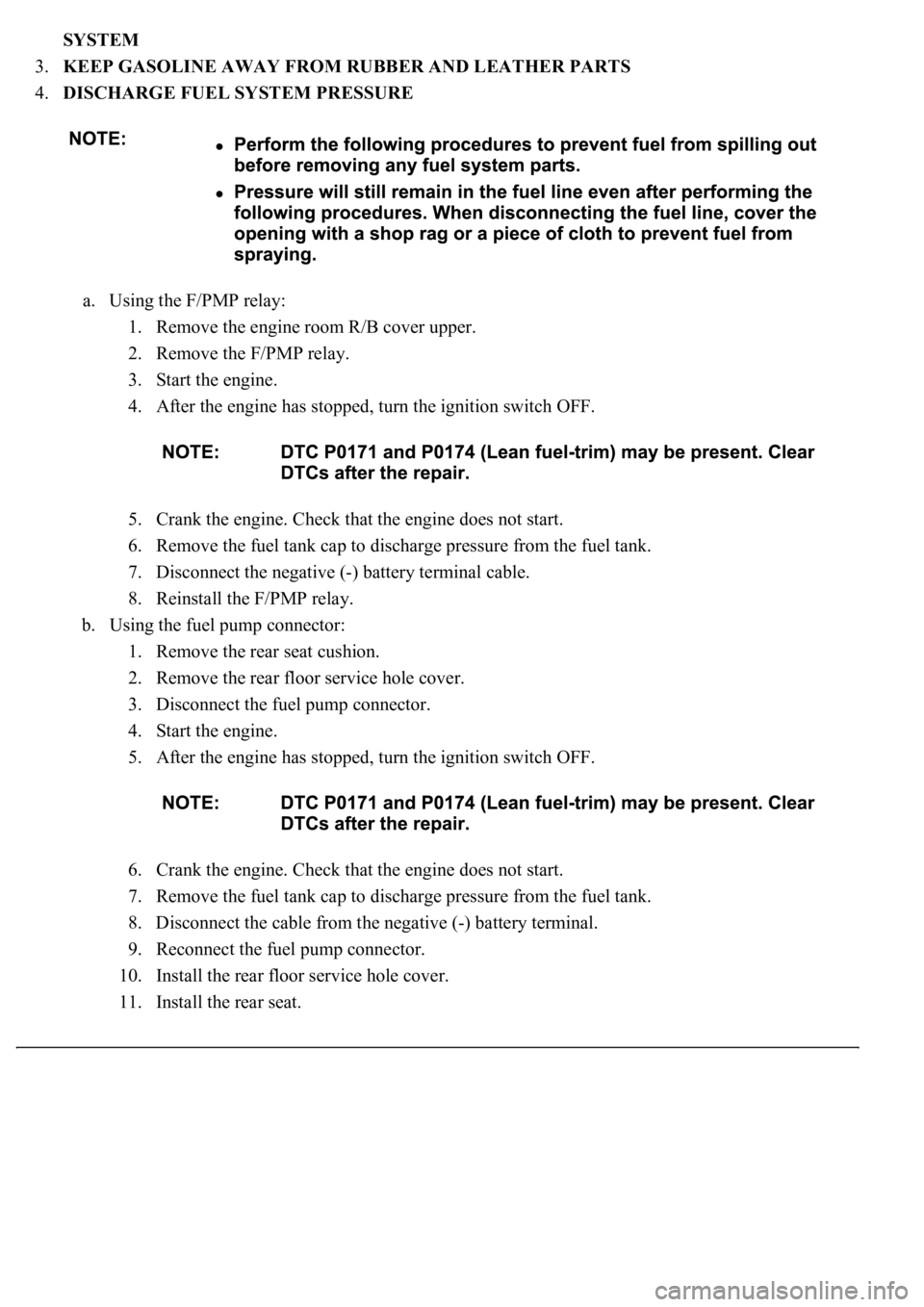
SYSTEM
3.KEEP GASOLINE AWAY FROM RUBBER AND LEATHER PARTS
4.DISCHARGE FUEL SYSTEM PRESSURE
a. Using the F/PMP relay:
1. Remove the engine room R/B cover upper.
2. Remove the F/PMP relay.
3. Start the engine.
4. After the engine has stopped, turn the ignition switch OFF.
5. Crank the engine. Check that the engine does not start.
6. Remove the fuel tank cap to discharge pressure from the fuel tank.
7. Disconnect the negative (-) battery terminal cable.
8. Reinstall the F/PMP relay.
b. Using the fuel pump connector:
1. Remove the rear seat cushion.
2. Remove the rear floor service hole cover.
3. Disconnect the fuel pump connector.
4. Start the engine.
5. After the engine has stopped, turn the ignition switch OFF.
6. Crank the engine. Check that the engine does not start.
7. Remove the fuel tank cap to discharge pressure from the fuel tank.
8. Disconnect the cable from the negative (-) battery terminal.
9. Reconnect the fuel pump connector.
10. Install the rear floor service hole cover.
11. Install the rear seat.
Page 4110 of 4500
Fig. 11: Covering Disconnected Pipe And Connector With Plastic Bag
Courtesy of TOYOTA MOTOR SALES, U.S.A., INC.
f. Observe these precautions when connecting the fuel tube connector (quick type).
1. Check that there is no damage or foreign matter on the part of the pipe that contacts the
connector.
2. Align the axis of the connector with the axis of the pipe. Push the pipe into the connector
until the connector makes a `click' sound. If the connection is too tight, apply a small amount
of fresh engine oil on the tip of the pipe.
Fig. 12: Aligning Axis Of Connector With Axis Of Pipe
Courtesy of TOYOTA MOTOR SALES, U.S.A., INC.
3. After connecting the pipe and connector, try to pull them apart to confirm that they are
securely connected.
4. Install the No. 1 fuel pipe clamp to the connector.
Page 4112 of 4500
Fig. 14: Connecting Hand-Held Tester (With CAN VIM) To DLC3 Connector Terminal
Courtesy of TOYOTA MOTOR SALES, U.S.A., INC.
3. Select the ACTIVE TEST mode on the hand-held tester.
HINT:
Please refer to the hand-held tester operator's manual for further details.
4. Check that there are no leaks from any part of the fuel system.
5. Turn the ignition switch LOCK.
6. Disconnect the hand-held tester from the DLC3.
ON-VEHICLE INSPECTION
1.CHECK FUEL PUMP OPERATION
a. Connect the hand-held tester (with CAN VIM) to the DLC3.
b. Turn the ignition switch ON and push the hand-held tester main switch ON.
Do not start the engine.
Page 4115 of 4500
pressure regulator.
i. Disconnect the hand-held tester from the DLC3.
j. Start the engine.
k. Measure the fuel pressure at idle.
Fuel pressure: 304 to 343 kPa (3.1 to 3.5 kgf/cm2, 44 to 50 psi)
l. Stop the engine.
m. Check that the fuel pressure remains as specified for 5 minutes after the engine has stopped.
Fuel pressure: 147 kPa (1.5 kgf/cm2, 21 psi) or more
If pressure is not as specified, check the fuel pump, pressure regulator and/or injectors.
n. After checking fuel pressure, disconnect the negative (-) terminal cable from the battery and
carefully remove the SST to prevent gasoline from spilling.
SST 09268-45014
o. Reinstall the fuel pressure pulsation damper to the RH delivery pipe (see REPLACEMENT
).
p. Reconnect the negative (-) terminal cable to the battery.
q. Check for fuel leaks.
3.INSPECT FUEL PUMP
Page 4199 of 4500
ON-VEHICLE INSPECTION
1.INSPECT REFRIGERANT VOLUME
a. Check the sight glass on the liquid tube.
Test conditions:
Engine is running at 1,500 rpm
Single A/C:
Blower speed control switch at "HI" position
Dual A/C:
Front blower switch at "HI" position
Rear blower switch at "HI" position
A/C switch ON
Single A/C:
Temperature control switch at "MAX. COOL" position
Dual A/C:
Rear temperature control switch at "MAX. COOL" position
Front driver side temperature control switch at "MAX. COOL" position
Front passenger side temperature control switch at "MAX. COOL" position
Fully open the doors
Page 4227 of 4500

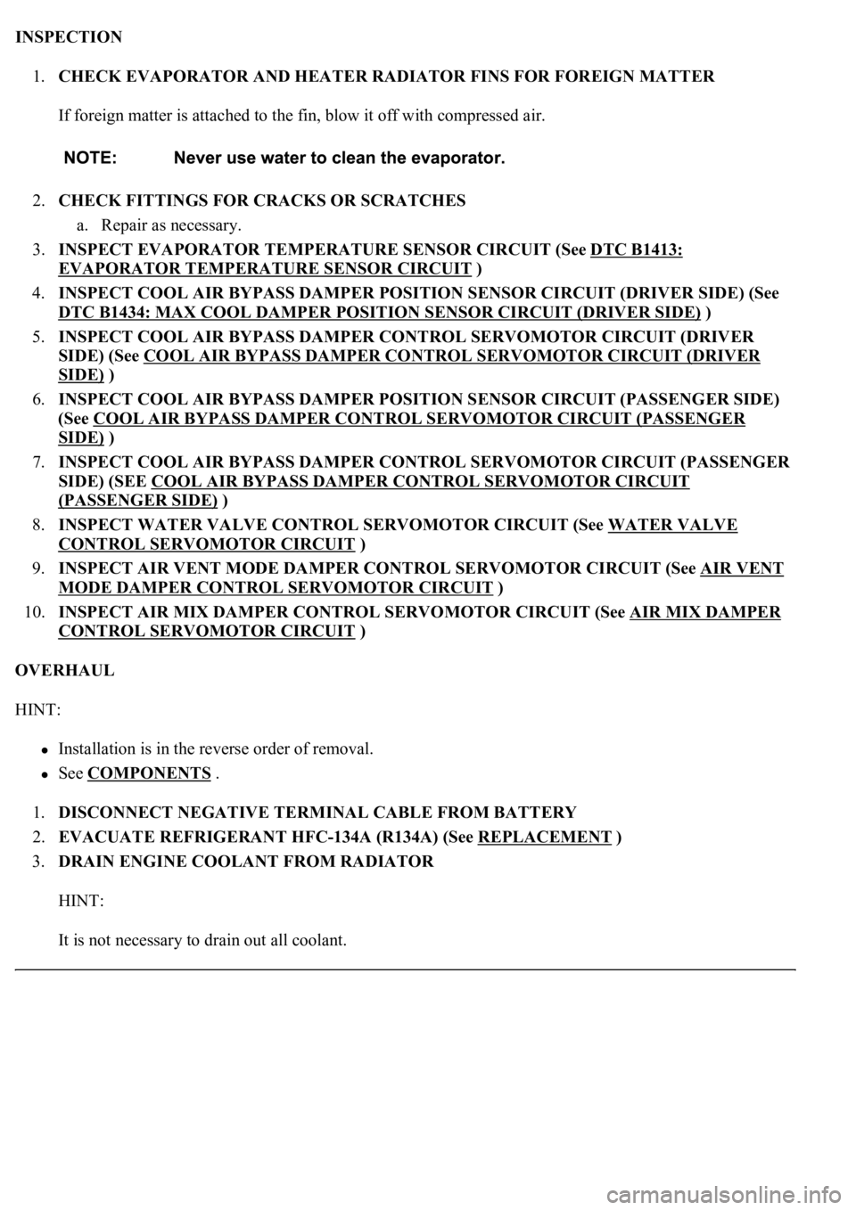
INSPECTION
1.CHECK EVAPORATOR AND HEATER RADIATOR FINS FOR FOREIGN MATTER
If foreign matter is attached to the fin, blow it off with compressed air.
2.CHECK FITTINGS FOR CRACKS OR SCRATCHES
a. Repair as necessary.
3.INSPECT EVAPORATOR TEMPERATURE SENSOR CIRCUIT (See DTC B1413:
EVAPORATOR TEMPERATURE SENSOR CIRCUIT )
4.INSPECT COOL AIR BYPASS DAMPER POSITION SENSOR CIRCUIT (DRIVER SIDE) (See
DTC B1434: MAX COOL DAMPER POSITION SENSOR CIRCUIT (DRIVER SIDE)
)
5.INSPECT COOL AIR BYPASS DAMPER CONTROL SERVOMOTOR CIRCUIT (DRIVER
SIDE) (See COOL AIR BYPASS DAMPER CONTROL SERVOMOTOR CIRCUIT (DRIVER
SIDE) )
6.INSPECT COOL AIR BYPASS DAMPER POSITION SENSOR CIRCUIT (PASSENGER SIDE)
(See COOL AIR BYPASS DAMPER CONTROL SERVOMOTOR CIRCUIT (PASSENGER
SIDE) )
7.INSPECT COOL AIR BYPASS DAMPER CONTROL SERVOMOTOR CIRCUIT (PASSENGER
SIDE) (SEE COOL AIR BYPASS DAMPER CONTROL SERVOMOTOR CIRCUIT
(PASSENGER SIDE) )
8.INSPECT WATER VALVE CONTROL SERVOMOTOR CIRCUIT (See WATER VALVE
CONTROL SERVOMOTOR CIRCUIT )
9.INSPECT AIR VENT MODE DAMPER CONTROL SERVOMOTOR CIRCUIT (See AIR VENT
MODE DAMPER CONTROL SERVOMOTOR CIRCUIT )
10.INSPECT AIR MIX DAMPER CONTROL SERVOMOTOR CIRCUIT (See AIR MIX DAMPER
CONTROL SERVOMOTOR CIRCUIT )
OVERHAUL
HINT:
Installation is in the reverse order of removal.
See COMPONENTS .
1.DISCONNECT NEGATIVE TERMINAL CABLE FROM BATTERY
2.EVACUATE REFRIGERANT HFC-134A (R134A) (See REPLACEMENT
)
3.DRAIN ENGINE COOLANT FROM RADIATOR
HINT:
It is not necessar
y to drain out all coolant.
Page 4256 of 4500
Fig. 70: Installing Suction Tube Sub-Assy B
Courtesy of TOYOTA MOTOR SALES, U.S.A., INC.
40.CONNECT NEGATIVE TERMINAL CABLE TO BATTERY
41.ADD ENGINE COOLANT (See REPLACEMENT
)
42.CHARGE REFRIGERANT (See REPLACEMENT
)
43.WARM UP ENGINE
44.CHECK FOR ENGINE COOLANT LEAKS (See REPLACEMENT
)
45.INSPECT FOR REFRIGERANT LEAKAGE (See REPLACEMENT
)
COMPONENTS