Page 1815 of 4500
Fig. 68: Identifying Front Seat Inner Belt Assy (Driver Side) Connector Wire Harness View
Courtesy of TOYOTA MOTOR SALES, U.S.A., INC.
OK: GO TO NEXT STEP
5.CHECK HARNESS AND CONNECTOR (FRONT SEAT INNER BELT ASSY - DRIVER SIDE
JUNCTION BLOCK) (SEE HOW TO PROCEED WITH TROUBLESHOOTING
)
a. Disconnect the B4, A23 connectors.
b. Measure the resistance according to the value (s) in the table below.
Standard
B4 AND A23 CONNECTORS RESISTANCE SPECIFICATIONS
Tester ConnectionConditionSpecified Condition
B4-2 - A23-10AlwaysBelow 1 ohms
A23-10 - Body groundAlways10 kohms or higher
Page 1823 of 4500
Fig. 73: Identifying B5 And A25 Connector Terminals
Courtesy of TOYOTA MOTOR SALES, U.S.A., INC.
NG: REPAIR OR REPLACE HARNESS OR CONNECTOR
OK: REPLACE AIRBAG SENSOR ASSY CENTER (SEE HOW TO PROCEED WITH
TROUBLESHOOTING )
6.INSPECT COMBINATION METER ASSY
a. Disconnect the clock assy connector.
b. Measure the voltage according to the value (s) in the table below.
Standard
VOLTAGE SPECIFICATIONS
NG: Go to step 8
Fig. 74: Identifying C12 Connector Terminals
Terminal NoConditionSpecified condition
C12-9 - Body groundIgnition switch ON, Passenger seat belt is unfastened10 to 14 V
Page 1824 of 4500
Courtesy of TOYOTA MOTOR SALES, U.S.A., INC.
OK: GO TO NEXT STEP
7.INSPECT CLOCK ASSY
a. Disconnect the clock assy connector.
b. Measure the voltage according to the value (s) in the table below.
Standard
CLOCK ASSY CONNECTOR TERMINALS VOLTAGE SPECIFICATIONS
NG: REPAIR OR REPLACE HARNESS OR CONNECTOR
Fig. 75: Identifying Clock Assy Connector Terminals Front View
Terminal NoConditionSpecified condition
C10-7 - C10-5Ignition switch ON, Passenger seat belt is unfastened10 to 14 V
Page 1825 of 4500
Courtesy of TOYOTA MOTOR SALES, U.S.A., INC.
OK: REPLACE CLOCK ASSY
8.CHECK HARNESS AND CONNECTOR (CLOCK ASSY - COMBINATION METER ASSY)
(SEE HOW TO PROCEED WITH TROUBLESHOOTING
)
a. Disconnect the C10 and C12 connectors.
b. Measure the resistance according to the value (s) in the table below.
Standard
C10 AND C12 CONNECTORS RESISTANCE SPECIFICATIONS
Tester ConnectionConditionSpecified Condition
C12-9 - C10-7AlwaysBelow 1 ohms
C12-9 - Body groundAlways10 kohms or higher
Page 1836 of 4500

OK:
Light control can be changed within the specified range by actual operation.
NG: Go to step 2
OK: REPLACE COMBINATION METER ASSY (SEE OVERHAUL
)
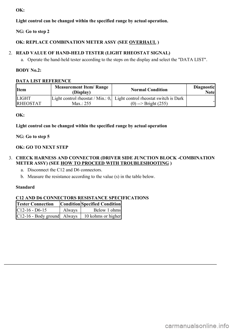
2.READ VALUE OF HAND-HELD TESTER (LIGHT RHEOSTAT SIGNAL)
a. Operate the hand-held tester according to the steps on the display and select the "DATA LIST".
BODY No.2:
DATA LIST REFERENCE
OK:
Light control can be changed within the specified range by actual operation
NG: Go to step 5
OK: GO TO NEXT STEP
3.CHECK HARNESS AND CONNECTOR (DRIVER SIDE JUNCTION BLOCK -COMBINATION
METER ASSY) (SEE HOW TO PROCEED WITH TROUBLESHOOTING
)
a. Disconnect the C12 and D6 connectors.
b. Measure the resistance according to the value (s) in the table below.
Standard
C12 AND D6 CONNECTORS RESISTANCE SPECIFICATIONS
ItemMeasurement Item/ Range
(Display)Normal ConditionDiagnostic
Note
LIGHT
RHEOSTATLight control rheostat / Min.: 0,
Max.: 255Light control rheostat switch is Dark
(0) --> Bright (255)-
Tester ConnectionConditionSpecified Condition
C12-16 - D6-15AlwaysBelow 1 ohms
C12-16 - Body groundAlways10 kohms or higher
Page 1838 of 4500
Fig. 84: Identifying Light Control Rheostat Connector Terminals
Courtesy of TOYOTA MOTOR SALES, U.S.A., INC.
NG: REPAIR OR REPLACE HARNESS OR CONNECTOR
OK: GO TO NEXT STEP
4.REPLACE DRIVER SIDE JUNCTION BLOCK
OK:
Normal operation
NG: REPLACE COMBINATION METER ASSY (SEE OVERHAUL
)
OK: END
5.INSPECT LIGHT CONTROL RHEOSTAT
a. Disconnect the light control rheostat connector.
b. Measure the voltage according to the value (s) in the table below.
Standard
LIGHT CONTROL RHEOSTAT VOLTAGE SPECIFICATIONS
NG: REPLACE LIGHT CONTROL RHEOSTAT
Terminal NoConditionSpecified condition
1 - 2Rheostat knob turned fully clockwiseApprox. 0 kohms
1 - 2Rheostat knob turned fully counterclockwiseApprox. 10 +/- 2 kohms
1 - 3AlwaysApprox. 10 +/- 2 kohms
4 - 1,3Rheostat knob turned fully counterclockwise10 kohms or higher
4 - 1,3Rheostat knob turned to fully clockwiseBelow 1 ohms
Page 1839 of 4500
Fig. 85: Identifying D6 And R4 Connector Terminals
Courtesy of TOYOTA MOTOR SALES, U.S.A., INC.
6.CHECK HARNESS AND CONNECTOR (LIGHT CONTROL RHEOSTAT - DRIVER SIDE
JUNCTION BLOCK) (SEE HOW TO PROCEED WITH TROUBLESHOOTING
)
a. Disconnect the D6 and R4 connectors.
b. Measure the resistance according to the value (s) in the table below.
Standard
D6 AND R4 CONNECTORS RESISTANCE SPECIFICATIONS
Tester ConnectionConditionSpecified Condition
D6-20 - R4-3AlwaysBelow 1 ohms
D6-22 - R4-2AlwaysBelow 1 ohms
D6-21 - R4-1AlwaysBelow 1 ohms
D6-1 - R4-4AlwaysBelow 1 ohms
Page 1842 of 4500
7.REPLACE DRIVER SIDE JUNCTION BLOCK
OK:
Normal operation
NG: REPLACE COMBINATION METER ASSY (SEE OVERHAUL
)
OK: END
1.INSPECT SPEEDOMETER
a. Check the operation.
b. Using a speedometer tester, inspect the speedometer for acceptable indication error and check the
operation of the odometer.
REFERENCE: KM/H (CANADA)
SPEEDOMETER ACCEPTABLE INDICATION
REFERENCE: MPH (U.S.A)
SPEEDOMETER ACCEPTABLE INDICATION
Standard indicationAcceptable range
20 km/h18.0 to 23.0 km/h
40 km/h38.0 to 42.0 km/h
60 km/h57.0 to 61.5 km/h
80 km/h76.5 to 81.5 km/h
100 km/h96.5 to 101.5 km/h
120 km/h116.0 to 121.5 km/h
140 km/h136.0 to 142.0 km/h
160 km/h155.5 to 162.5 km/h
180 km/h175.0 to 183.0 km/h
200 km/h194.5 to 203.5 km/h
Standard indicationAcceptable range
20 mph18.5 to 21.5 mph
40 mph38.5 to 41.5 mph
60 mph59.0 to 62.5 mph
80 mph79.0 to 83.0 mph
100 mph99.0 to 104.0 mph
120 mph119.0 to 125.0 mph