Page 1684 of 4500
NG: REPAIR OR REPLACE HARNESS AND CONNECTOR
OK: Go to next step
7.INSPECT RELAY (Marking: P-IG1)
a. Remove the P-IG1 relay from the passenger side J/B.
b. Measure the resistance of the relay.
Standard:
TESTER CONNECTION AND SPECIFIED CONDITION
Fig. 64: Identifying P
-IG1 Relay Terminals And Circuit
Courtesy of TOYOTA MOTOR SALES, U.S.A., INC.
NG: REPAIR OR REPLACE HARNESS AND CONNECTOR
OK: REPLACE DRIVER SIDE JUNCTION BLOCK
Tester ConnectionSpecified Condition
3 - 510 kohms or higher
3 - 5Below 1 ohms (when battery voltage is applied to terminal 1 and 2)
Page 1695 of 4500
Fig. 73: Identifying L14 Luggage Room J/B ECU Connector Terminals
Courtesy of TOYOTA MOTOR SALES, U.S.A., INC.
NG: REPLACE LUGGAGE ROOM JUNCTION BLOCK ASSY
OK: REPLACE LUGGAGE ROOM JUNCTION BLOCK ECU
10.INSPECT REAR SEAT HEATER SWITCH
a. Disconnect the C31 switch connector.
b. Measure the resistance of the switch.
Standard:
TESTER CONNECTION AND SPECIFIED CONDITION
Tester ConnectionSwitch ConditionSpecified Condition
11 (SWL) - 8 (E)OFF10 kohms or higher
11 (SWL) - 8 (E)ONBelow 1 ohms
4 (SWR) - 8 (E)OFF10 kohms or higher
Page 1735 of 4500
REMOVAL AND INSTALLATION OF BATTERY TERMINAL
a. Before performing electronic work, disconnect the battery negative (-) terminal cable in order to prevent
it from shorting and burning out.
b. When disconnecting and reconnecting the battery cable, turn the ignition switch and lighting switch off
and loosen the terminal nut completely. Perform operations without twisting or prying on the terminal.
c. When the battery terminal cable is removed, the memories of the clock, radio, DTCs, etc. are erased. So
before removing it, check and make a note of them.
INITIALIZE SYSTEM REFERENCE
System NameSee Procedure
Front Power Seat Control SystemINITIALIZATION
Page 1800 of 4500

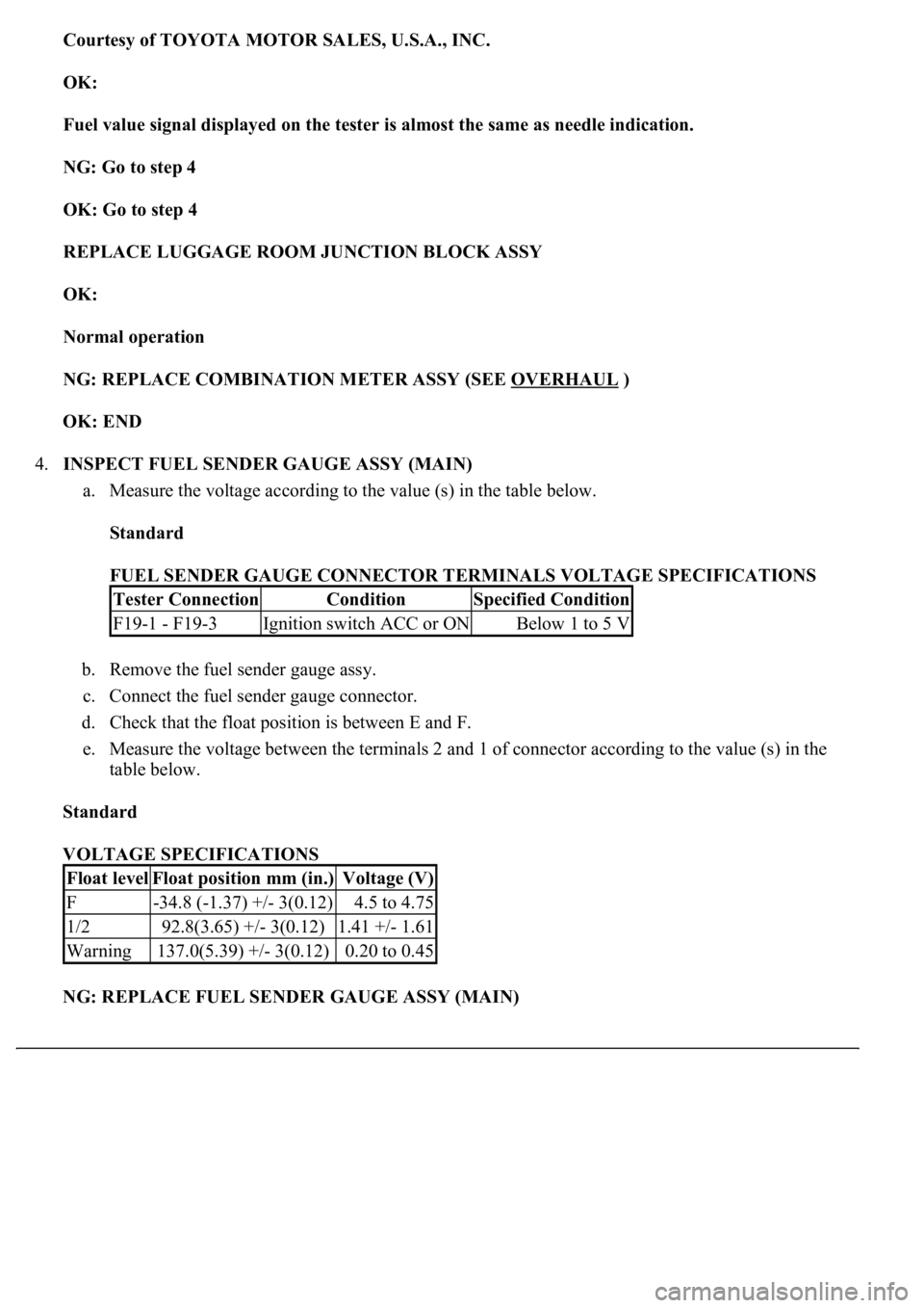
Courtesy of TOYOTA MOTOR SALES, U.S.A., INC.
OK:
Fuel value signal displayed on the tester is almost the same as needle indication.
NG: Go to step 4
OK: Go to step 4
REPLACE LUGGAGE ROOM JUNCTION BLOCK ASSY
OK:
Normal operation
NG: REPLACE COMBINATION METER ASSY (SEE OVERHAUL
)
OK: END
4.INSPECT FUEL SENDER GAUGE ASSY (MAIN)
a. Measure the voltage according to the value (s) in the table below.
Standard
FUEL SENDER GAUGE CONNECTOR TERMINALS VOLTAGE SPECIFICATIONS
b. Remove the fuel sender gauge assy.
c. Connect the fuel sender gauge connector.
d. Check that the float position is between E and F.
e. Measure the voltage between the terminals 2 and 1 of connector according to the value (s) in the
table below.
Standard
VOLTAGE SPECIFICATIONS
NG: REPLACE FUEL SENDER GAUGE ASSY (MAIN)
Tester ConnectionConditionSpecified Condition
F19-1 - F19-3Ignition switch ACC or ONBelow 1 to 5 V
Float levelFloat position mm (in.)Voltage (V)
F-34.8 (-1.37) +/- 3(0.12)4.5 to 4.75
1/292.8(3.65) +/- 3(0.12)1.41 +/- 1.61
Warning137.0(5.39) +/- 3(0.12)0.20 to 0.45
Page 1802 of 4500
Fig. 59: Identifying Float Position
Courtesy of TOYOTA MOTOR SALES, U.S.A., INC.
OK: GO TO NEXT STEP
5.CHECK HARNESS AND CONNECTOR (FUEL SENDER GAUGE ASSY - LUGGAGE ROOM
JUNCTION BLOCK ASSY) (SEE HOW TO PROCEED WITH TROUBLESHOOTING
)
a. Disconnect the F19, L13 and L14 connectors.
b. Measure the resistance according to the value (s) in the table below.
Standard
RESISTANCE SPECIFICATIONS
Tester ConnectionConditionSpecified Condition
L14-6 - F19-1AlwaysBelow 1 ohms
L14-4 - F19-2AlwaysBelow 1 ohms
L13-10 - F19-3AlwaysBelow 1 ohms
Page 1805 of 4500
Fig. 60: Identifying Fuel Sender Gauge Assy And Luggage Room Junction Block Assy Connector
Terminals
Courtesy of TOYOTA MOTOR SALES, U.S.A., INC.
NG: REPAIR OR REPLACE HARNESS OR CONNECTOR
OK: GO TO NEXT STEP
6.INSPECT FUEL SENDER GAUGE ASSY (SUB)
a. Measure the voltage according to the value (s) in the table below.
Standard
VOLTAGE SPECIFICATIONS
b. Remove the fuel sender gauge assy.
c. Connect the fuel sender gauge connector.
d. Check that the float position is between E and F.
e. Measure the voltage between the terminals 2 and 1 of connector according to the value (s) in the
table below.
Standard
VOLTAGE SPECIFICATIONS
Tester ConnectionConditionSpecified Condition
F20-1 - F20-3Ignition switch ACC or ONBelow 1 to 5 V
Float levelFloat position mm (in.)Voltage (V)
F1.4(0.06) +/- 3(0.12)4.5 to 4.75
1/2190.2(7.49) +/- 3(0.12)0.45 +/- 0.65
Warning195.7(7.70) +/- 3(0.12)0.20 to 0.45
Page 1807 of 4500
Fig. 62: Identifying Float Position
Courtesy of TOYOTA MOTOR SALES, U.S.A., INC.
NG: REPLACE FUEL SENDER GAUGE ASSY (SUB)
OK: GO TO NEXT STEP
7.CHECK HARNESS AND CONNECTOR (FUEL SENDER GAUGE ASSY - LUGGAGE ROOM
JUNCTION BLOCK ASSY) (SEE HOW TO PROCEED WITH TROUBLESHOOTING
)
a. Disconnect the F20, L13 and 14 connectors.
b. Measure the resistance according to the value (s) in the table below.
Standard
RESISTANCE SPECIFICATIONS
Tester ConnectionConditionSpecified Condition
L14-7 - F19-1AlwaysBelow 1 ohms
L13-9 - F19-2AlwaysBelow 1 ohms
L14-15 - F19-3AlwaysBelow 1 ohms
Page 1810 of 4500
Fig. 63: Identifying Fuel Sender Gauge Assy And Luggage Room Junction Block Assy Connector
Terminals
Courtesy of TOYOTA MOTOR SALES, U.S.A., INC.
NG: REPAIR OR REPLACE HARNESS OR CONNECTOR
OK: REPLACE LUGGAGE ROOM JUNCTION BLOCK ASSY
WIRING DIAGRAM
Fig. 64: Water Temperature Receiver Gauge Wiring Diagram
Courtesy of TOYOTA MOTOR SALES, U.S.A., INC.
INSPECTION PROCEDURE
HINT:
If there is an open or short in the engine coolant temperature sensor circuit, the ECM outputs DTCs. Perform
troubleshooting with the "SFI System 10-2".
1.PERFORM ACTIVE TEST BY HAND-HELD TESTER
a. Operate the hand-held tester according to the steps on the display and select the "ACTIVE TEST".
METER:
ACTIVE TEST REFERENCE