Page 2304 of 4500
Fig. 97: Inspecting Combination Switch Assy (Rear Right Side)
Courtesy of TOYOTA MOTOR SALES, U.S.A., INC.
Page 2422 of 4500

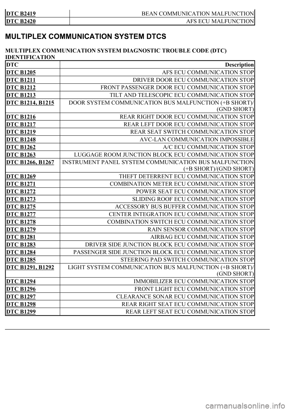
MULTIPLEX COMMUNICATION SYSTEM DIAGNOSTIC TROUBLE CODE (DTC)
IDENTIFICATION
DTC B2419 BEAN COMMUNICATION MALFUNCTION
DTC B2420 AFS ECU MALFUNCTION
DTCDescription
DTC B1205 AFS ECU COMMUNICATION STOP
DTC B1211 DRIVER DOOR ECU COMMUNICATION STOP
DTC B1212 FRONT PASSENGER DOOR ECU COMMUNICATION STOP
DTC B1213 TILT AND TELESCOPIC ECU COMMUNICATION STOP
DTC B1214, B1215 DOOR SYSTEM COMMUNICATION BUS MALFUNCTION (+B SHORT)/
(GND SHORT)
DTC B1216 REAR RIGHT DOOR ECU COMMUNICATION STOP
DTC B1217 REAR LEFT DOOR ECU COMMUNICATION STOP
DTC B1219 REAR SEAT SWITCH COMMUNICATION STOP
DTC B1248 AVC-LAN COMMUNICATION IMPOSSIBLE
DTC B1262 A/C ECU COMMUNICATION STOP
DTC B1263 LUGGAGE ROOM JUNCTION BLOCK ECU COMMUNICATION STOP
DTC B1266, B1267 INSTRUMENT PANEL SYSTEM COMMUNICATION BUS MALFUNCTION
(+B SHORT)/(GND SHORT)
DTC B1269 THEFT DETERRENT ECU COMMUNICATION STOP
DTC B1271 COMBINATION METER ECU COMMUNICATION STOP
DTC B1272 POWER SEAT ECU COMMUNICATION STOP
DTC B1273 SLIDING ROOF ECU COMMUNICATION STOP
DTC B1275 ACCESSORY BUS BUFFER COMMUNICATION STOP
DTC B1277 CENTER INTEGRATION ECU COMMUNICATION STOP
DTC B1278 COMBINATION SWITCH ECU COMMUNICATION STOP
DTC B1279 RAIN SENSOR COMMUNICATION STOP
DTC B1281 AIRBAG ECU COMMUNICATION STOP
DTC B1283 DRIVER SIDE JUNCTION BLOCK ECU COMMUNICATION STOP
DTC B1284 PASSENGER SIDE JUNCTION BLOCK ECU COMMUNICATION STOP
DTC B1285 STEERING PAD SWITCH COMMUNICATION STOP
DTC B1291, B1292 LIGHT SYSTEM COMMUNICATION BUS MALFUNCTION (+B SHORT)/
(GND SHORT)
DTC B1294 IMMOBILIZER ECU COMMUNICATION STOP
DTC B1296 FRONT LIGHT ECU COMMUNICATION STOP
DTC B1297 CLEARANCE SONAR ECU COMMUNICATION STOP
DTC B1298 REAR RIGHT SEAT ECU COMMUNICATION STOP
DTC B1299 REAR LEFT SEAT ECU COMMUNICATION STOP
Page 2434 of 4500
Fig. 6: Dynamic Laser Cruise Control System Control Example Chart
Courtesy of TOYOTA MOTOR SALES, U.S.A., INC.
Setting of the vehicle distance can be changed to 3 distances by operating the distance control
switch (DISP2 button): long (approximately 75 m (246 ft)), middle (approximately 50 m (164 ft)),
and short (approximately 30 m (98 ft)) when vehicle speed is approximately 90 km/h (55 mph).
HINT:
Vehicle distance increases and decreases in accordance with vehicle speed.
Controlling condition is indicated on the combination meter multi-information display.
2.FUNCTION OF MAIN COMPONENTS
Page 2449 of 4500
Fig. 17: [Display NORM]
Courtesy of TOYOTA MOTOR SALES, U.S.A., INC.
3.INSPECT STEERING PAD SWITCH ASSY
a. Turn the ignition switch to the ON position.
b. Push on the ON-OFF button of the cruise control main switch.
c. Push on the distance control switch (DISP2) of the steering pad switch.
d. Check that the indication of vehicle-to-vehicle distance, which is shown in the multi-information
displa
y on the combination meter, changes from "LONG", "MIDDLE" to "SHORT" in that order.
Page 2450 of 4500
Fig. 18: Multi-Information Display Chart On Combination Meter
Courtesy of TOYOTA MOTOR SALES, U.S.A., INC.
HINT:
The indication is immediately set to "LONG" each time the engine is started.
If a normal system code is displayed during the DTC check but the problem still occurs, check the suspected
areas for each problem symptom in the order given in the table below and proceed to the relevant
troubleshooting page.
HINT:
Inspect the "Fuse" and "Relay" before confirming the suspected areas as shown in the chart below. Inspect each
suspected area for the correspondin
g symptom in numerical order.
Page 2460 of 4500
Fig. 29: Identifying Blinking Pattern Of CRUISE Main Indicator Light
Courtesy of TOYOTA MOTOR SALES, U.S.A., INC.
2.DESCRIPTION
a. The ECM controls the dynamic laser cruise control system of the vehicle. The data and DTCs
relating to the dynamic laser cruise control system can be read from the DLC3 of the vehicle. If
either DTC or CRUISE OK is not displayed in the multi-information display on the combination
meter when checking for DTCs, there may be a problem with the combination meter or the CAN
communication and multiplex communication system.
Use the hand-held tester to check and solve the problem.
3.CHECK THE DLC3
a. The vehicle's ECM uses ISO 9141-2 for communication. The terminal arrangement of the DLC3
complies with SAE J1962 and matches the ISO 9141-2 format.
Page 2462 of 4500

tester to the DLC3, turned the ignition switch to the ON position and operated the tester, there is a
problem on either the vehicle side or the tool side.
If communication is normal when the tool is connected to another vehicle, inspect the DLC3 on the
original vehicle.
If communication is still impossible when the tool is connected to another vehicle, the problem is
probably in the tool itself, so consult the Service Department listed in the tool's instruction manual.
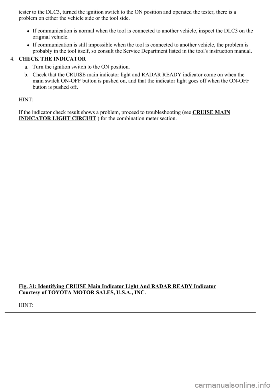
4.CHECK THE INDICATOR
a. Turn the ignition switch to the ON position.
b. Check that the CRUISE main indicator light and RADAR READY indicator come on when the
main switch ON-OFF button is pushed on, and that the indicator light goes off when the ON-OFF
button is pushed off.
HINT:
If the indicator check result shows a problem, proceed to troubleshooting (see CRUISE MAIN
INDICATOR LIGHT CIRCUIT ) for the combination meter section.
<0029004c004a0011000300160014001d0003002c0047004800510057004c0049005c004c0051004a0003002600350038002c00360028000300300044004c00510003002c00510047004c004600440057005200550003002f004c004a004b00570003002400
51004700030035002400270024003500030035002800240027[Y Indicator
Courtesy of TOYOTA MOTOR SALES, U.S.A., INC.
HINT:
Page 2469 of 4500

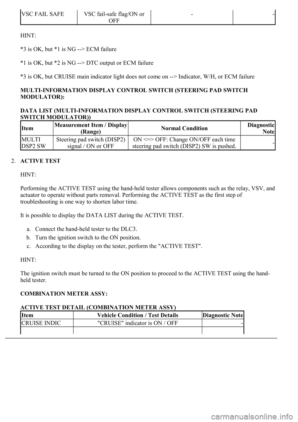
HINT:
*3 is OK, but *1 is NG --> ECM failure
*1 is OK, but *2 is NG --> DTC output or ECM failure
*3 is OK, but CRUISE main indicator light does not come on --> Indicator, W/H, or ECM failure
MULTI-INFORMATION DISPLAY CONTROL SWITCH (STEERING PAD SWITCH
MODULATOR):
DATA LIST (MULTI-INFORMATION DISPLAY CONTROL SWITCH (STEERING PAD
SWITCH MODULATOR))
2.ACTIVE TEST
HINT:
Performing the ACTIVE TEST using the hand-held tester allows components such as the relay, VSV, and
actuator to operate without parts removal. Performing the ACTIVE TEST as the first step of
troubleshooting is one way to shorten labor time.
It is possible to display the DATA LIST during the ACTIVE TEST.
a. Connect the hand-held tester to the DLC3.
b. Turn the ignition switch to the ON position.
c. According to the display on the tester, perform the "ACTIVE TEST".
HINT:
The ignition switch must be turned to the ON position to proceed to the ACTIVE TEST using the hand-
held tester.
COMBINATION METER ASSY:
ACTIVE TEST DETAIL (COMBINATION METER ASSY)
VSC FAIL SAFEVSC fail-safe flag/ON or
OFF--
ItemMeasurement Item / Display
(Range)Normal ConditionDiagnostic
Note
MULTI
DSP2 SWSteering pad switch (DISP2)
signal / ON or OFFON <=> OFF: Change ON/OFF each time
steering pad switch (DISP2) SW is pushed.-
ItemVehicle Condition / Test DetailsDiagnostic Note
CRUISE INDIC"CRUISE" indicator is ON / OFF-