Page 25 of 4500
HINT:
<003a004b0048005100030057004b00480003005300440055004e004c0051004a0003004500550044004e00480003004c00560003004400530053004f004c0048004700030052005500030057004b00480003004f004800590048004f000300520049000300
57004b00480003004500550044004e004800030049004f0058[id is low, the BRAKE warning light
comes on.
b. When the ignition switch is turned to the ON position, check that the ABS warning light, TRAC
OFF indicator light, BRAKE warning light and SLIP indicator light come on for approximately 3
seconds.
HINT:
If the ECU was any stored DTCs, the ABS warning light, "VSC" is displayed on the multi-
information display and TRAC OFF indicator light come on.
If the indicator does not come on, inspect it the bulb is blown out, and also the wire harness
between the skid control ECU and the combination meter.
Page 43 of 4500
Fig. 31: Connecting Hand-Held Tester To DLC3
Courtesy of TOYOTA MOTOR SALES, U.S.A., INC.
a. Checking DTCs.
1. Connect the hand-held tester to the DLC3.
2. Turn the ignition switch to the ON position.
3. Read the DTCs following the prompts on the tester screen.
HINT:
Refer to the hand-held tester operator's manual for further details.
2.DTC CHECK (USING SST CHECK WIRE)
a. Checking DTCs of ABS system.
1. Using SST, connect terminals TC and CG of the DLC3.
SST 09843-18040
2. Turn the ignition switch to the ON position.
3. Read the DTC from the ABS warnin
g light on the combination meter.
Page 46 of 4500
SST 09843-18040
2. Turn the ignition switch to the ON position.
3. Read the DTC from multi-information display on the combination meter.
HINT:
At this time, "VSC OK", is displayed when VSC system is in normal condition. If any DTC is
detected, "VSC 31", for example, will be displayed.
If there are 2 or more DTC, DTC will be displayed in ascending order of the number.
If no code appears, inspect the VSC warning information circuit and TC and CG terminal circuit.
Fig. 34: Identifying VSC Position
Courtesy of TOYOTA MOTOR SALES, U.S.A., INC.
TROUBLE AREA REFERENCE
Trouble AreaSee Procedure
TC and CG terminal circuitTC AND CG TERMINAL CIRCUIT
Page 55 of 4500

HINT:
If a malfunction code is displayed during the DTC check, check the circuit indicated by the table below.
DIAGNOSTIC TROUBLE CODE CHART
SMF (BA-SOL)Turns TRAC solenoid SMF (BA-SOL)
ON / OFFOperation of solenoid (clicking sound)
can be heard
SMRTurns TRAC solenoid SMR ON / OFFOperation of solenoid (clicking sound)
can be heard
SOL RELAYTurns ABS solenoid relay ON / OFFOperation of solenoid (clicking sound)
can be heard
ABS MOT RELAYTurns ABS motor relay ON / OFFOperation of solenoid (clicking sound)
can be heard
ABS WARN LIGHTTurns ABS warning light ON / OFFObserve combination meter
VSC WARN LIGHTTurns VSC warning light ON / OFFObserve combination meter
VSC / TRC OFF INDTurns VSC / TRC OFF indicator ON /
OFFObserve combination meter
SLIP INDI LIGHTTurns SLIP indicator light ON / OFFObserve combination meter
BRAKE WRN LIGHTTurns BRAKE warning light ON / OFFObserve combination meter
VSC / BR WARN
BUZTurns VSC / BRAKE warning buzzer
ON / OFFBuzzer can be heard
STP LIGHT RELAYTurns stop light ON / OFFStop light come on
DTCDescription
DTC C0200/31, C0205/32RIGHT/LEFT FRONT SPEED SENSOR
DTC C0210/33, C0215/34RIGHT/LEFT REAR SPEED SENSOR
DTC C0226/21, C0236/22, C0246/23,
C0256/24, C1225/25
SFR/SFL/SRR/SRL/SM SOLENOID CIRCUIT
DTC C0273/13, C0274/14, C1361/91OPEN CIRCUIT IN ABS MOTOR RELAY CIRCUIT,
B+ SHORT CIRCUIT IN ABS MOTOR RELAY
CIRCUIT, SHORT CIRCUIT IN ABS MOTOR FAIL
SAFE RELAY CIRCUIT
DTC C0278/11, C0279/12OPEN/SHORT CIRCUIT IN ABS SOLENOID
RELAY CIRCUIT
DTC C1201/51ENGINE CONTROL SYSTEM MALFUNCTION
DTC C1203/53ECM COMMUNICATION CIRCUIT
MALFUNCTION
DTC C1210/36, C1336/39ZERO POINT CALIBRATION OF YAW
RATE/DECELERATION SENSOR UNDONE
DTC C1223/43ABS CONTROL SYSTEM MALFUNCTION
DTC C1231/31MALFUNCTION IN STEERING ANGLE SENSOR
CIRCUIT
Page 154 of 4500

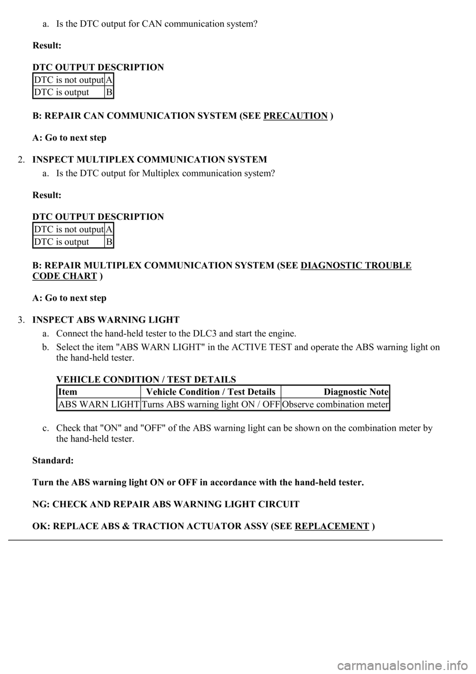
a. Is the DTC output for CAN communication system?
Result:
DTC OUTPUT DESCRIPTION
B: REPAIR CAN COMMUNICATION SYSTEM (SEE PRECAUTION
)
A: Go to next step
2.INSPECT MULTIPLEX COMMUNICATION SYSTEM
a. Is the DTC output for Multiplex communication system?
Result:
DTC OUTPUT DESCRIPTION
B: REPAIR MULTIPLEX COMMUNICATION SYSTEM (SEE DIAGNOSTIC TROUBLE
CODE CHART )
A: Go to next step
3.INSPECT ABS WARNING LIGHT
a. Connect the hand-held tester to the DLC3 and start the engine.
b. Select the item "ABS WARN LIGHT" in the ACTIVE TEST and operate the ABS warning light on
the hand-held tester.
VEHICLE CONDITION / TEST DETAILS
c. Check that "ON" and "OFF" of the ABS warning light can be shown on the combination meter by
the hand-held tester.
Standard:
Turn the ABS warning light ON or OFF in accordance with the hand-held tester.
NG: CHECK AND REPAIR ABS WARNING LIGHT CIRCUIT
OK: REPLACE ABS & TRACTION ACTUATOR ASSY (SEE REPLACEMENT
)
DTC is not outputA
DTC is outputB
DTC is not outputA
DTC is outputB
ItemVehicle Condition / Test DetailsDiagnostic Note
ABS WARN LIGHTTurns ABS warning light ON / OFFObserve combination meter
Page 155 of 4500
CIRCUIT DESCRIPTION
If the ECU stores DTC, the VSC warning light comes on in the combination meter.
The skid control ECU is connected to the combination meter via CAN and MPX communications.
WIRING DIAGRAM
Page 159 of 4500
Fig. 118: Identifying Skid Control ECU Terminals
Courtesy of TOYOTA MOTOR SALES, U.S.A., INC.
OK: REPLACE ABS & TRACTION ACTUATOR ASSY (SEE REPLACEMENT
)
CIRCUIT DESCRIPTION
If the ECU stores DTC, the VSC warning light comes on in the combination meter.
The skid control ECU is connected to the combination meter via CAN and MPX communications.
WIRING DIAGRAM
Page 161 of 4500

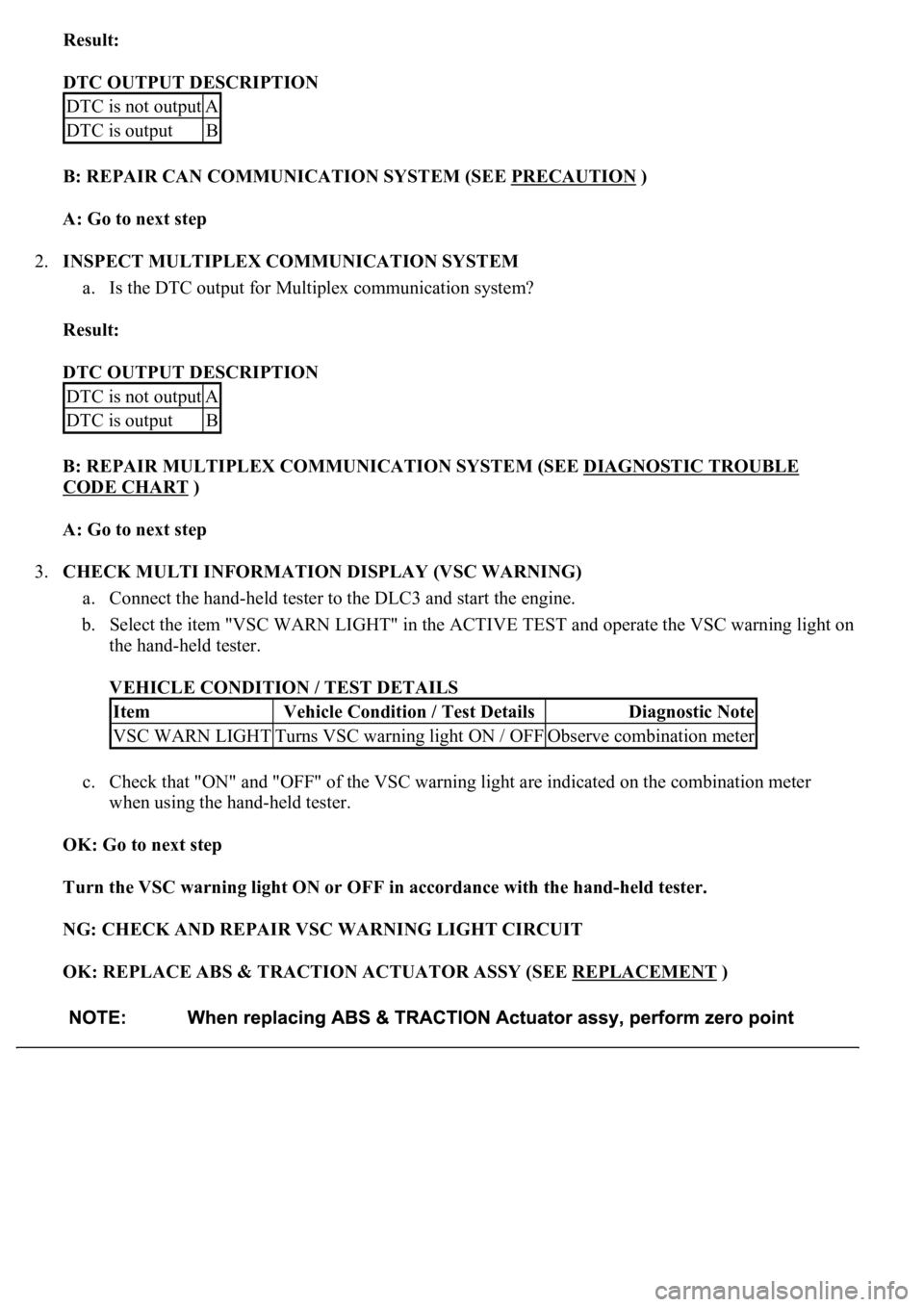
Result:
DTC OUTPUT DESCRIPTION
B: REPAIR CAN COMMUNICATION SYSTEM (SEE PRECAUTION
)
A: Go to next step
2.INSPECT MULTIPLEX COMMUNICATION SYSTEM
a. Is the DTC output for Multiplex communication system?
Result:
DTC OUTPUT DESCRIPTION
B: REPAIR MULTIPLEX COMMUNICATION SYSTEM (SEE DIAGNOSTIC TROUBLE
CODE CHART )
A: Go to next step
3.CHECK MULTI INFORMATION DISPLAY (VSC WARNING)
a. Connect the hand-held tester to the DLC3 and start the engine.
b. Select the item "VSC WARN LIGHT" in the ACTIVE TEST and operate the VSC warning light on
the hand-held tester.
VEHICLE CONDITION / TEST DETAILS
c. Check that "ON" and "OFF" of the VSC warning light are indicated on the combination meter
when using the hand-held tester.
OK: Go to next step
Turn the VSC warning light ON or OFF in accordance with the hand-held tester.
NG: CHECK AND REPAIR VSC WARNING LIGHT CIRCUIT
OK: REPLACE ABS & TRACTION ACTUATOR ASSY (SEE REPLACEMENT
)
DTC is not outputA
DTC is outputB
DTC is not outputA
DTC is outputB
ItemVehicle Condition / Test DetailsDiagnostic Note
VSC WARN LIGHTTurns VSC warning light ON / OFFObserve combination meter