Page 718 of 4500

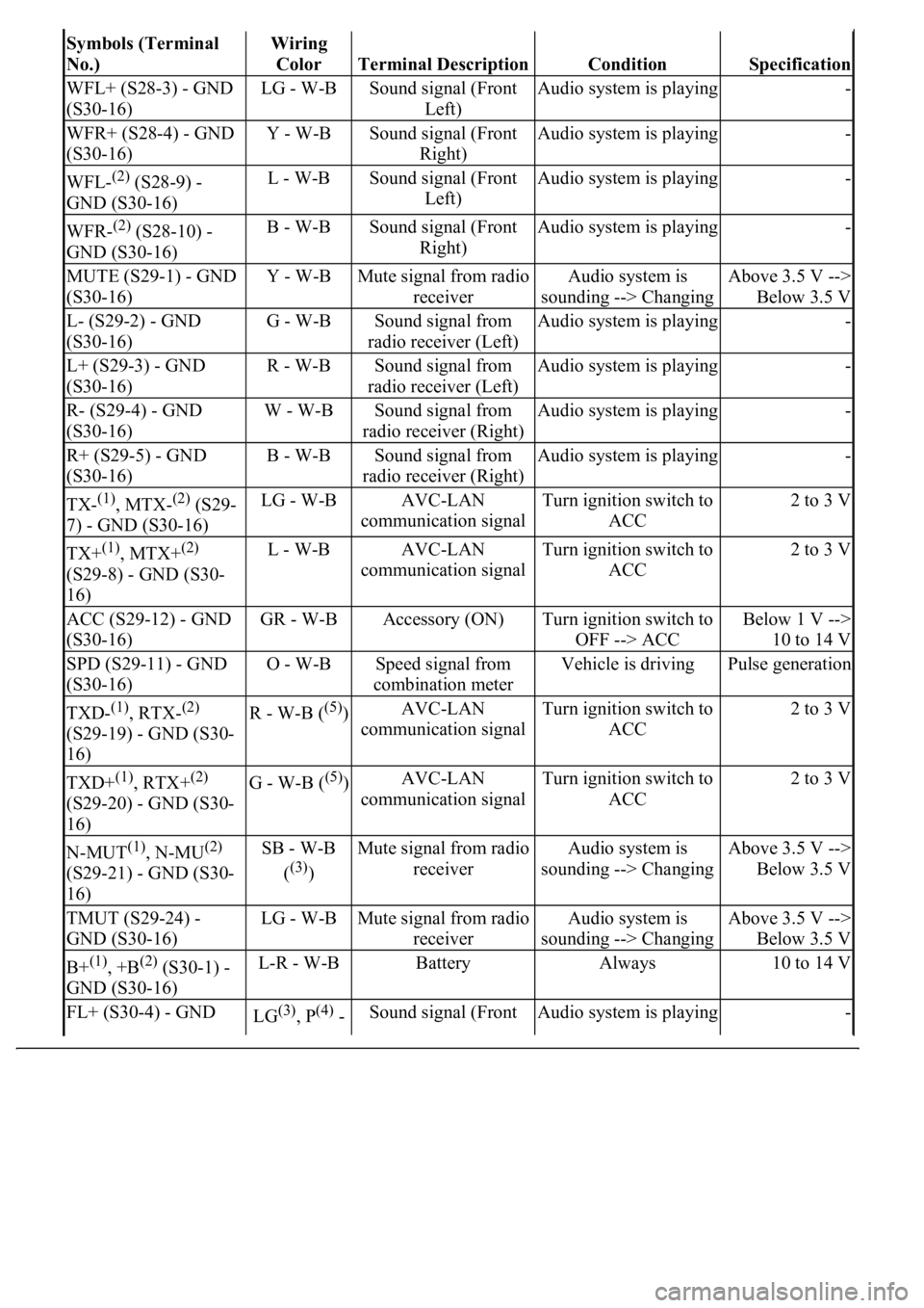
Symbols (Terminal
No.)Wiring
Color
Terminal DescriptionConditionSpecification
WFL+ (S28-3) - GND
(S30-16)LG - W-BSound signal (Front
Left)Audio system is playing-
WFR+ (S28-4) - GND
(S30-16)Y - W-BSound signal (Front
Right)Audio system is playing-
WFL-(2) (S28-9) -
GND (S30-16)L - W-BSound signal (Front
Left)Audio system is playing-
WFR-(2) (S28-10) -
GND (S30-16)B - W-BSound signal (Front
Right)Audio system is playing-
MUTE (S29-1) - GND
(S30-16)Y - W-BMute signal from radio
receiverAudio system is
sounding --> ChangingAbove 3.5 V -->
Below 3.5 V
L- (S29-2) - GND
(S30-16)G - W-BSound signal from
radio receiver (Left)Audio system is playing-
L+ (S29-3) - GND
(S30-16)R - W-BSound signal from
radio receiver (Left)Audio system is playing-
R- (S29-4) - GND
(S30-16)W - W-BSound signal from
radio receiver (Right)Audio system is playing-
R+ (S29-5) - GND
(S30-16)B - W-BSound signal from
radio receiver (Right)Audio system is playing-
TX-(1), MTX-(2) (S29-
7) - GND (S30-16)LG - W-BAVC-LAN
communication signalTurn ignition switch to
ACC2 to 3 V
TX+(1), MTX+(2)
(S29-8) - GND (S30-
16)L - W-BAVC-LAN
communication signalTurn ignition switch to
ACC2 to 3 V
ACC (S29-12) - GND
(S30-16)GR - W-BAccessory (ON)Turn ignition switch to
OFF --> ACCBelow 1 V -->
10 to 14 V
SPD (S29-11) - GND
(S30-16)O - W-BSpeed signal from
combination meterVehicle is drivingPulse generation
TXD-(1), RTX-(2)
(S29-19) - GND (S30-
16)R - W-B ((5))AVC-LAN
communication signalTurn ignition switch to
ACC2 to 3 V
TXD+(1), RTX+(2)
(S29-20) - GND (S30-
16)G - W-B ((5))AVC-LAN
communication signalTurn ignition switch to
ACC2 to 3 V
N-MUT(1), N-MU(2)
(S29-21) - GND (S30-
16)SB - W-B
(
(3))
Mute signal from radio
receiverAudio system is
sounding --> ChangingAbove 3.5 V -->
Below 3.5 V
TMUT (S29-24) -
GND (S30-16)LG - W-BMute signal from radio
receiverAudio system is
sounding --> ChangingAbove 3.5 V -->
Below 3.5 V
B+(1), +B(2) (S30-1) -
GND (S30-16)L-R - W-BBatteryAlways10 to 14 V
FL+ (S30-4) - GND LG(3), P(4) - Sound signal (Front Audio system is playing-
Page 784 of 4500
Fig. 66: Identifying Stereo Components Tuner Connector
Courtesy of TOYOTA MOTOR SALES, U.S.A., INC.
OK: PROCEED TO NEXT CIRCUIT INSPECTION SHOWN ON PROBLEM SYMPTOMS
TABLE
CIRCUIT DESCRIPTION
This circuit is necessary for the stereo component amplifier assy for the ASL (Auto Sound Leveliser). Speed
signals are received from the combination meter.
The ASL function automatically adjusts the sound data in order to enable to hear the clear audio sound even
when the vehicle noise is increased (as vehicle noise increased, the volume is turned up etc.)
Standard System: Using speed signals and a microphone for the ASL built into the stereo component amplifier
assy.
Mark Levinson System: Using speed signals.
Page 785 of 4500
WIRING DIAGRAM
Fig. 67: Identifying Stereo Component Amplifier Assy Wiring Diagram
Courtesy of TOYOTA MOTOR SALES, U.S.A., INC.
INSPECTION PROCEDURE
1.CHECK HARNESS AND CONNECTOR (STEREO COMPONENT AMPLIFIER ASSY -
COMBINATION METER ASSY)
a. Disconnect the connectors from the stereo component amplifier assy S29 and combination meter
assy C12.
b. Measure the resistance according to the value (s) in the table below.
Standard:
TESTER CONNECTION CONDITION CHART
Tester connectionConditionSpecified condition
SPD - +SAlwaysBelow 1 ohms
SPD - Body groundAlways10 kohms or higher
Page 788 of 4500
Fig. 70: Identifying Combination Meter Assembly Connector
Courtesy of TOYOTA MOTOR SALES, U.S.A., INC.
OK: Go to next step
2.INSPECT COMBINATION METER ASSY
a. Check the voltage.
1. Jack up either of the front wheels.
2. Adjust the shift lever to the neutral position.
3. Measure the voltage between the terminals +S and body ground while turning the front wheel
slowly.
Standard:
Page 789 of 4500
TESTER CONNECTION CONDITION CHART
Fig. 71: Inspecting Combination Meter Assy
Courtesy of TOYOTA MOTOR SALES, U.S.A., INC.
Tester connectionConditionSpecification
+S - Body groundIgnition switch ONVoltage is pulsed
Page 790 of 4500
Fig. 72: Identifying Blinking Pattern
Courtesy of TOYOTA MOTOR SALES, U.S.A., INC.
NG: GO TO COMBINATION METER SYSTEM (SEE PRECAUTION
)
OK: PROCEED TO NEXT CIRCUIT INSPECTION SHOWN ON PROBLEM SYMPTOMS
TABLE
CIRCUIT DESCRIPTION
This circuit sends the signal to the stereo component amplifier to mute the noise. Because of that, the noise
produced by changing the sound source ceases.
In addition, this circuit is used to mute the sound when the navigation system performs voice guide.
If there is an open in the circuit, noise can be heard from the speaker when changing the sound source.
When the vehicle is equipped with the navigation system, audio sound keeps coming out from the speaker on
the driver's side while the voice navigation is in operation.
If there is a short in the circuit, even though the stereo component amplifier assy is normal, no sound or only
extremely small sound can be produced.
WIRING DIAGRAM
Page 823 of 4500

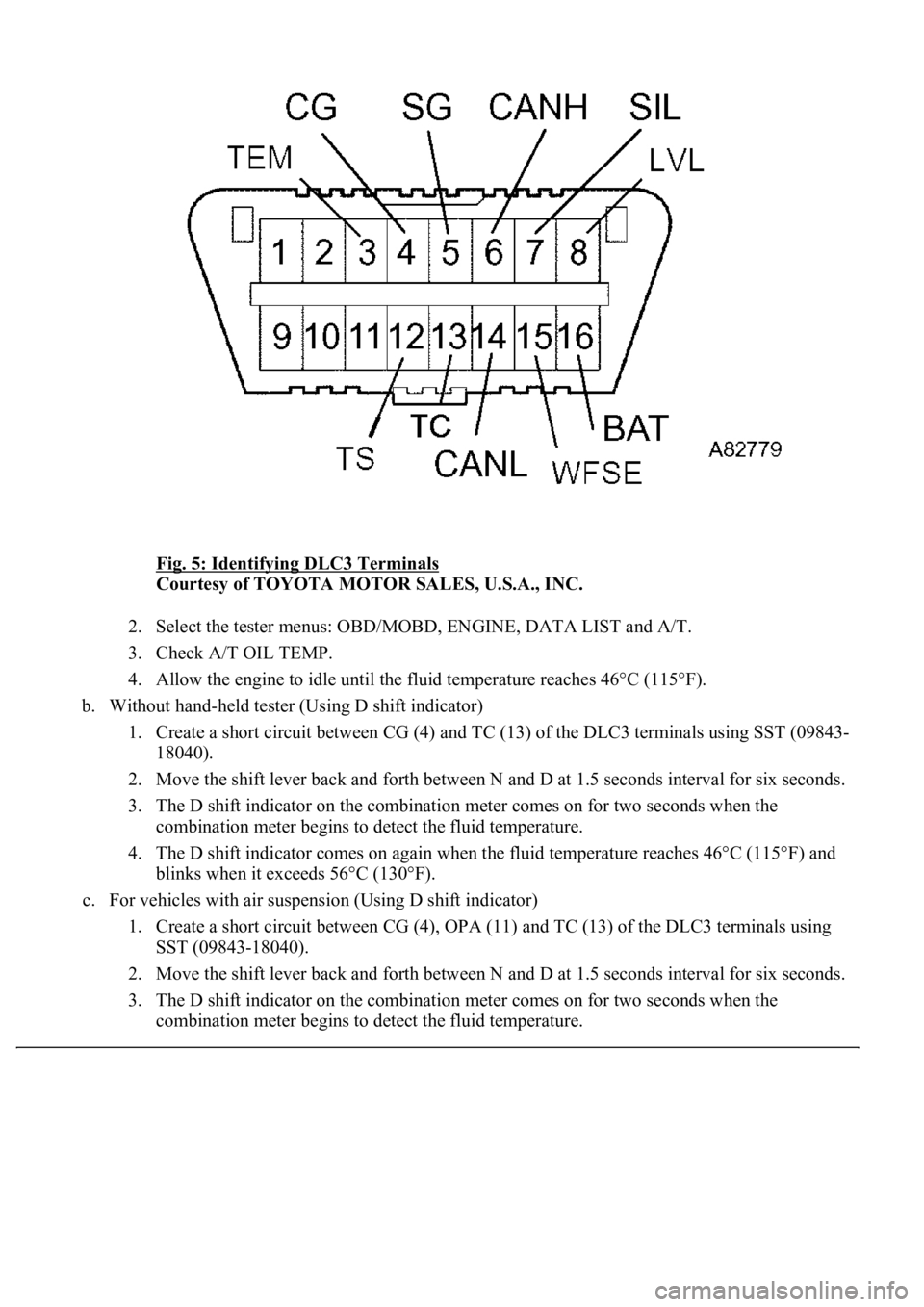
Fig. 5: Identifying DLC3 Terminals
Courtesy of TOYOTA MOTOR SALES, U.S.A., INC.
2. Select the tester menus: OBD/MOBD, ENGINE, DATA LIST and A/T.
3. Check A/T OIL TEMP.
4. Allow the engine to idle until the fluid temperature reaches 46°C (115°F).
b. Without hand-held tester (Using D shift indicator)
1. Create a short circuit between CG (4) and TC (13) of the DLC3 terminals using SST (09843-
18040).
2. Move the shift lever back and forth between N and D at 1.5 seconds interval for six seconds.
3. The D shift indicator on the combination meter comes on for two seconds when the
combination meter begins to detect the fluid temperature.
4. The D shift indicator comes on again when the fluid temperature reaches 46°C (115°F) and
blinks when it exceeds 56°C (130°F).
c. For vehicles with air suspension (Using D shift indicator)
1. Create a short circuit between CG (4), OPA (11) and TC (13) of the DLC3 terminals using
SST (09843-18040).
2. Move the shift lever back and forth between N and D at 1.5 seconds interval for six seconds.
3. The D shift indicator on the combination meter comes on for two seconds when the
combination meter begins to detect the fluid temperature.
Page 985 of 4500

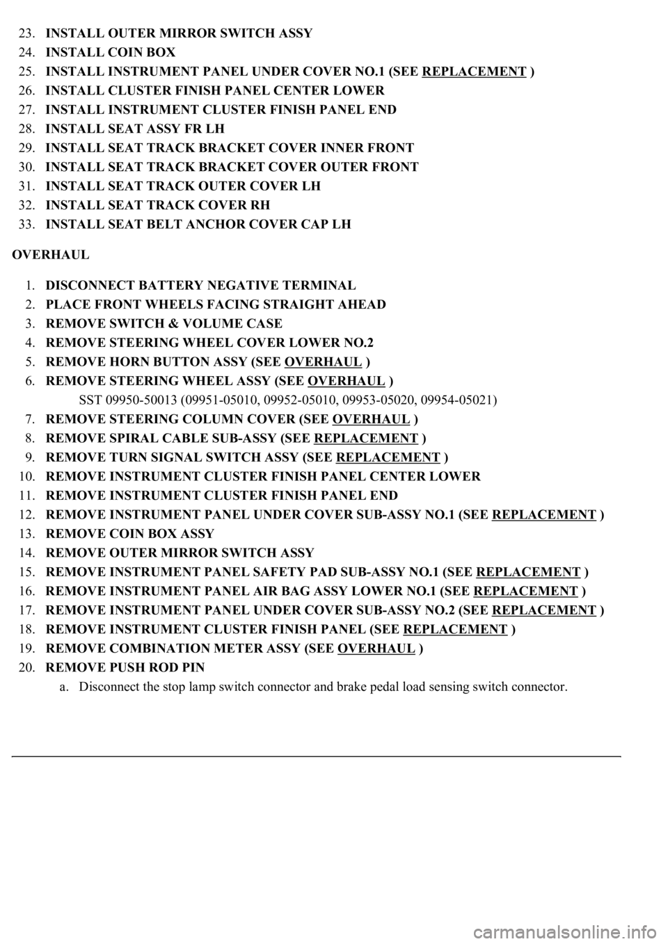
23.INSTALL OUTER MIRROR SWITCH ASSY
24.INSTALL COIN BOX
25.INSTALL INSTRUMENT PANEL UNDER COVER NO.1 (SEE REPLACEMENT
)
26.INSTALL CLUSTER FINISH PANEL CENTER LOWER
27.INSTALL INSTRUMENT CLUSTER FINISH PANEL END
28.INSTALL SEAT ASSY FR LH
29.INSTALL SEAT TRACK BRACKET COVER INNER FRONT
30.INSTALL SEAT TRACK BRACKET COVER OUTER FRONT
31.INSTALL SEAT TRACK OUTER COVER LH
32.INSTALL SEAT TRACK COVER RH
33.INSTALL SEAT BELT ANCHOR COVER CAP LH
OVERHAUL
1.DISCONNECT BATTERY NEGATIVE TERMINAL
2.PLACE FRONT WHEELS FACING STRAIGHT AHEAD
3.REMOVE SWITCH & VOLUME CASE
4.REMOVE STEERING WHEEL COVER LOWER NO.2
5.REMOVE HORN BUTTON ASSY (SEE OVERHAUL
)
6.REMOVE STEERING WHEEL ASSY (SEE OVERHAUL
)
<00360036003700030013001c001c001800130010001800130013001400160003000b0013001c001c00180014001000130018001300140013000f00030013001c001c00180015001000130018001300140013000f00030013001c001c001800160010001300
18001300150013000f00030013001c001c0018001700100013[5021)
7.REMOVE STEERING COLUMN COVER (SEE OVERHAUL
)
8.REMOVE SPIRAL CABLE SUB-ASSY (SEE REPLACEMENT
)
9.REMOVE TURN SIGNAL SWITCH ASSY (SEE REPLACEMENT
)
10.REMOVE INSTRUMENT CLUSTER FINISH PANEL CENTER LOWER
11.REMOVE INSTRUMENT CLUSTER FINISH PANEL END
12.REMOVE INSTRUMENT PANEL UNDER COVER SUB-ASSY NO.1 (SEE REPLACEMENT
)
13.REMOVE COIN BOX ASSY
14.REMOVE OUTER MIRROR SWITCH ASSY
15.REMOVE INSTRUMENT PANEL SAFETY PAD SUB-ASSY NO.1 (SEE REPLACEMENT
)
16.REMOVE INSTRUMENT PANEL AIR BAG ASSY LOWER NO.1 (SEE REPLACEMENT
)
17.REMOVE INSTRUMENT PANEL UNDER COVER SUB-ASSY NO.2 (SEE REPLACEMENT
)
18.REMOVE INSTRUMENT CLUSTER FINISH PANEL (SEE REPLACEMENT
)
19.REMOVE COMBINATION METER ASSY (SEE OVERHAUL
)
20.REMOVE PUSH ROD PIN
a. Disconnect the stop lamp switch connector and brake pedal load sensing switch connector.