Page 1786 of 4500

METER:
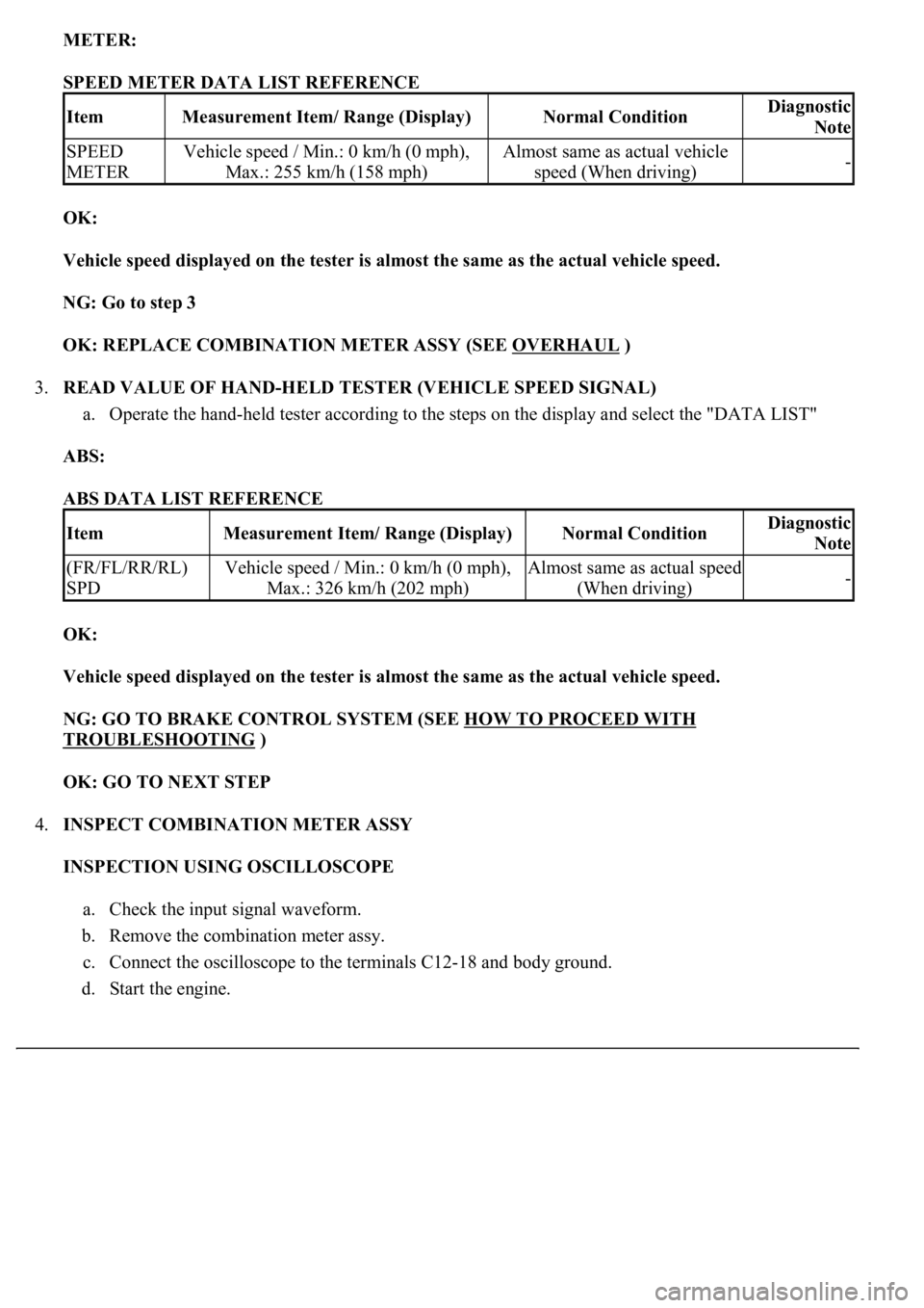
SPEED METER DATA LIST REFERENCE
OK:
Vehicle speed displayed on the tester is almost the same as the actual vehicle speed.
NG: Go to step 3
OK: REPLACE COMBINATION METER ASSY (SEE OVERHAUL
)
3.READ VALUE OF HAND-HELD TESTER (VEHICLE SPEED SIGNAL)
a. Operate the hand-held tester according to the steps on the display and select the "DATA LIST"
ABS:
ABS DATA LIST REFERENCE
OK:
Vehicle speed displayed on the tester is almost the same as the actual vehicle speed.
NG: GO TO BRAKE CONTROL SYSTEM (SEE HOW TO PROCEED WITH
TROUBLESHOOTING )
OK: GO TO NEXT STEP
4.INSPECT COMBINATION METER ASSY
INSPECTION USING OSCILLOSCOPE
a. Check the input signal waveform.
b. Remove the combination meter assy.
c. Connect the oscilloscope to the terminals C12-18 and body ground.
d. Start the en
gine.
ItemMeasurement Item/ Range (Display)Normal ConditionDiagnostic
Note
SPEED
METERVehicle speed / Min.: 0 km/h (0 mph),
Max.: 255 km/h (158 mph)Almost same as actual vehicle
speed (When driving)-
ItemMeasurement Item/ Range (Display)Normal ConditionDiagnostic
Note
(FR/FL/RR/RL)
SPDVehicle speed / Min.: 0 km/h (0 mph),
Max.: 326 km/h (202 mph)Almost same as actual speed
(When driving)-
Page 1788 of 4500
Fig. 47: Identifying Signal Waveform
Courtesy of TOYOTA MOTOR SALES, U.S.A., INC.
SIGNAL WAVEFORM CONDITIONS
OK:
As shown in the illustration
HINT:
As vehicle speed increases, the cycle of the signal waveform narrows.
NG: Go to step 5
OK: REPLACE COMBINATION METER ASSY (SEE OVERHAUL
)
ItemCondition
Tool setting5 V/DIV, 20 ms/DIV
Vehicle conditionDriving at approx. 20 Km/h (12 mph)
Page 1789 of 4500
5.CHECK HARNESS AND CONNECTOR (ABS & TRACTION ACTUATOR ASSY (VSC) -
COMBINATION METER ASSY) (SEE HOW TO PROCEED WITH TROUBLESHOOTING
)
a. Disconnect the C12 and S42 connectors.
b. Measure the resistance according to the value (s) in the table below.
Standard
C12 AND S42 CONNECTORS RESISTANCE SPECIFICATIONS
Tester ConnectionConditionSpecified Condition
C12-18 - S42-12AlwaysBelow 1 ohms
C12-18 - Body groundAlways10 kohms or higher
Page 1791 of 4500
Fig. 48: Identifying C12 And S42 Connectors
Courtesy of TOYOTA MOTOR SALES, U.S.A., INC.
NG: REPAIR OR REPLACE HARNESS AND CONNECTOR
OK: GO TO NEXT STEP
6.INSPECT ABS & TRACTION ACTUATOR ASSY (VSC)
a. Disconnect the S42 connector.
b. Measure the voltage according to the value (s) in the table below.
Standard
S42 connector VOLTAGE SPECIFICATIONS
NG: REPLACE COMBINATION METER ASSY (SEE OVERHAUL
)
Fig. 49: Identifying S42 Connector Terminals
Courtesy of TOYOTA MOTOR SALES, U.S.A., INC.
OK: GO TO BRAKE CONTROL SYSTEM (SEE HOW TO PROCEED WITH
TROUBLESHOOTING )
Tester ConnectionConditionSpecified Condition
S42-12 - Body groundIgnition switch ON10 to 14 V
Page 1792 of 4500
WIRING DIAGRAM
Fig. 50: Tachometer Wiring Diagram
Courtesy of TOYOTA MOTOR SALES, U.S.A., INC.
INSPECTION PROCEDURE
1.PERFORM ACTIVE TEST BY HAND-HELD TESTER
a. Operate the hand-held tester according to the steps on the display and select the "ACTIVE TEST".
METER:
TACHO METER ACTIVE TEST REFERENCE
OK:
Needle indication is normal.
NG: REPLACE COMBINATION METER ASSY (SEE OVERHAUL
)
OK: GO TO NEXT STEP
2.READ VALUE OF HAND-HELD TESTER (ENGINE SPEED SIGNAL)
a. Operate the han
d-held tester according to the steps on the display and select the "DATA LIST".
ItemTest DetailsDiagnostic
Note
TACHOMETEROrpm / 1000rpm / 2000rpm / 3000rpm / 4000rpm / 5000rpm /
6000rpm / 7000rpm-
Page 1793 of 4500

METER:
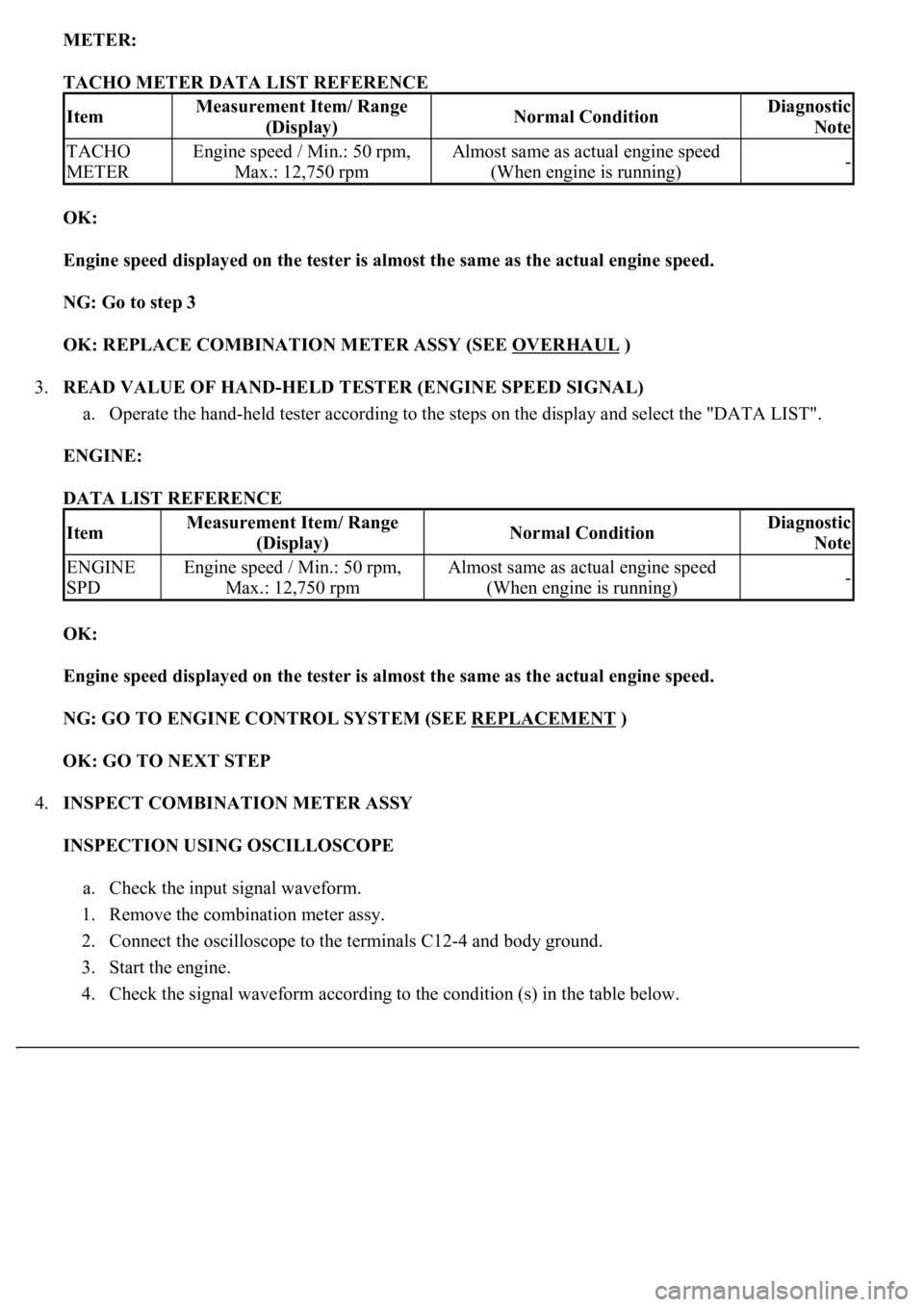
TACHO METER DATA LIST REFERENCE
OK:
Engine speed displayed on the tester is almost the same as the actual engine speed.
NG: Go to step 3
OK: REPLACE COMBINATION METER ASSY (SEE OVERHAUL
)
3.READ VALUE OF HAND-HELD TESTER (ENGINE SPEED SIGNAL)
a. Operate the hand-held tester according to the steps on the display and select the "DATA LIST".
ENGINE:
DATA LIST REFERENCE
OK:
Engine speed displayed on the tester is almost the same as the actual engine speed.
NG: GO TO ENGINE CONTROL SYSTEM (SEE REPLACEMENT
)
OK: GO TO NEXT STEP
4.INSPECT COMBINATION METER ASSY
INSPECTION USING OSCILLOSCOPE
a. Check the input signal waveform.
1. Remove the combination meter assy.
2. Connect the oscilloscope to the terminals C12-4 and body ground.
3. Start the engine.
4. Check the si
gnal waveform according to the condition (s) in the table below.
ItemMeasurement Item/ Range
(Display)Normal ConditionDiagnostic
Note
TACHO
METEREngine speed / Min.: 50 rpm,
Max.: 12,750 rpmAlmost same as actual engine speed
(When engine is running)-
ItemMeasurement Item/ Range
(Display)Normal ConditionDiagnostic
Note
ENGINE
SPDEngine speed / Min.: 50 rpm,
Max.: 12,750 rpmAlmost same as actual engine speed
(When engine is running)-
Page 1795 of 4500
Fig. 52: Identifying Signal Waveform
Courtesy of TOYOTA MOTOR SALES, U.S.A., INC.
NG: Go to step 5
OK: REPLACE COMBINATION METER ASSY (SEE OVERHAUL
)
5.CHECK HARNESS AND CONNECTOR (ECM - COMBINATION METER ASSY) (SEE HOW
TO PROCEED WITH TROUBLESHOOTING )
a. Disconnect the C12 and E2 connectors.
b. Measure the resistance according to the value (s) in the table below.
Standard
C12 AND E2 CONNECTORS RESISTANCE SPECIFICATIONS
Tester ConnectionConditionSpecified Condition
C12-4 - E2-16AlwaysBelow 1 ohms
C12-4 - Body groundAlways10 kohms or higher
Page 1797 of 4500
Fig. 53: Identifying C12 And E2 Connectors
Courtesy of TOYOTA MOTOR SALES, U.S.A., INC.
NG: REPAIR OR REPLACE HARNESS AND CONNECTOR
OK: GO TO NEXT STEP
6.INSPECT COMBINATION METER ASSY
a. Disconnect the E2 connector.
b. Measure the voltage according to the value (s) in the table below.
Standard
E2 CONNECTOR VOLTAGE SPECIFICATIONS
NG: REPLACE COMBINATION METER ASSY (SEE OVERHAUL
)
Fig. 54: Identifying E2 Connector
Tester ConnectionConditionSpecified Condition
E2-16 - Body groundIgnition switch ON10 to 14 V