Page 2470 of 4500

HINT:
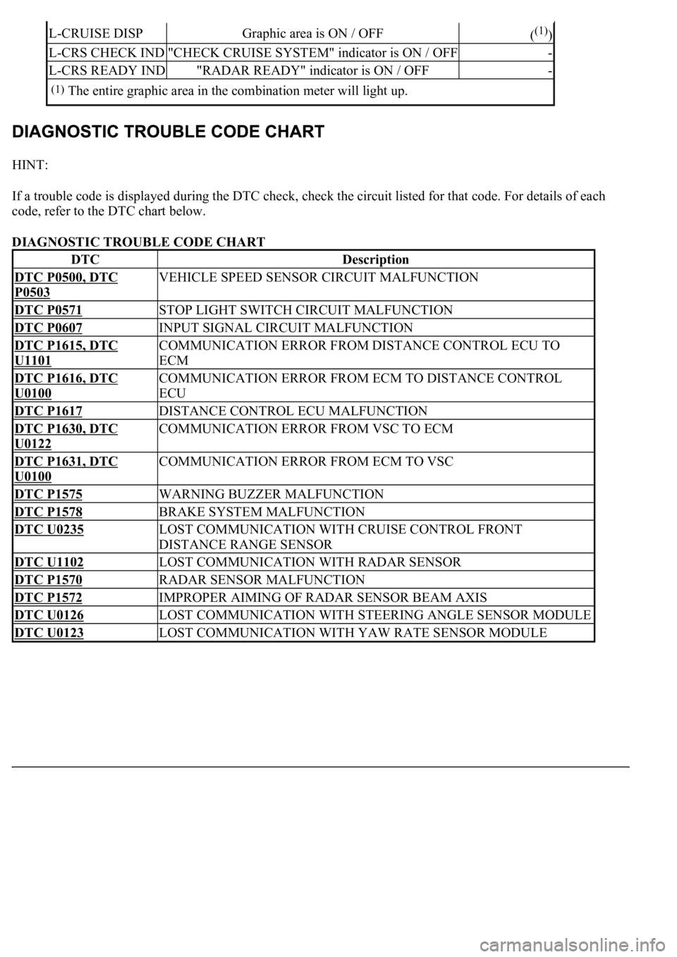
If a trouble code is displayed during the DTC check, check the circuit listed for that code. For details of each
code, refer to the DTC chart below.
DIAGNOSTIC TROUBLE CODE CHART
L-CRUISE DISPGraphic area is ON / OFF((1))
L-CRS CHECK IND"CHECK CRUISE SYSTEM" indicator is ON / OFF-
L-CRS READY IND"RADAR READY" indicator is ON / OFF-
(1)The entire graphic area in the combination meter will light up.
DTCDescription
DTC P0500, DTC
P0503
VEHICLE SPEED SENSOR CIRCUIT MALFUNCTION
DTC P0571STOP LIGHT SWITCH CIRCUIT MALFUNCTION
DTC P0607INPUT SIGNAL CIRCUIT MALFUNCTION
DTC P1615, DTC
U1101
COMMUNICATION ERROR FROM DISTANCE CONTROL ECU TO
ECM
DTC P1616, DTC
U0100
COMMUNICATION ERROR FROM ECM TO DISTANCE CONTROL
ECU
DTC P1617DISTANCE CONTROL ECU MALFUNCTION
DTC P1630, DTC
U0122
COMMUNICATION ERROR FROM VSC TO ECM
DTC P1631, DTC
U0100
COMMUNICATION ERROR FROM ECM TO VSC
DTC P1575WARNING BUZZER MALFUNCTION
DTC P1578BRAKE SYSTEM MALFUNCTION
DTC U0235LOST COMMUNICATION WITH CRUISE CONTROL FRONT
DISTANCE RANGE SENSOR
DTC U1102LOST COMMUNICATION WITH RADAR SENSOR
DTC P1570RADAR SENSOR MALFUNCTION
DTC P1572IMPROPER AIMING OF RADAR SENSOR BEAM AXIS
DTC U0126LOST COMMUNICATION WITH STEERING ANGLE SENSOR MODULE
DTC U0123LOST COMMUNICATION WITH YAW RATE SENSOR MODULE
Page 2519 of 4500

CIRCUIT DESCRIPTION
When the cruise control main switch is on, CRUISE main indicator light and READY indicator light come on.
This indicates the control condition (presence or absence of a vehicle in front, vehicle-to-vehicle distance, and
set vehicle speed) and fail-safe state through the multiplex communication system and CAN communication
system.
The master warning light and, CRUISE main indicator light come on and vehicle-to-vehicle distance
information is displayed on the combination meter as the alarm buzzer sounds.
Items such as "Clean Radar Sensor", "Cruise not Available", "Check Cruise System" and "Radar Cruise Ready"
are displayed in the multi-information display on the combination meter when the ECM detects signals from
each sensor and actuator and sends them to the combination meter via CAN and BEAN.
HINT:
If the vehicle in front in the same lane significantly decreases vehicle speed or another vehicle pulls in front of
your vehicle, adequate deceleration cannot be applied and the vehicle-to-vehicle distance will shorten. At this
time, the system sounds the buzzer and the master warning light blinks to warn the driver.
Each indicator in the dynamic laser cruise control uses CAN and BEAN for communication. Therefore if there
are any malfunctions in this circuit, check for DTCs in the CAN communication and multiplex communication
systems.
INSPECTION PROCEDURE
1.PERFORM ACTIVE TEST BY HAND-HELD TESTER
a. Connect the hand-held tester to the DLC3.
b. Check the cruise control switch by using ACTIVE TEST.
COMBINATION METER:
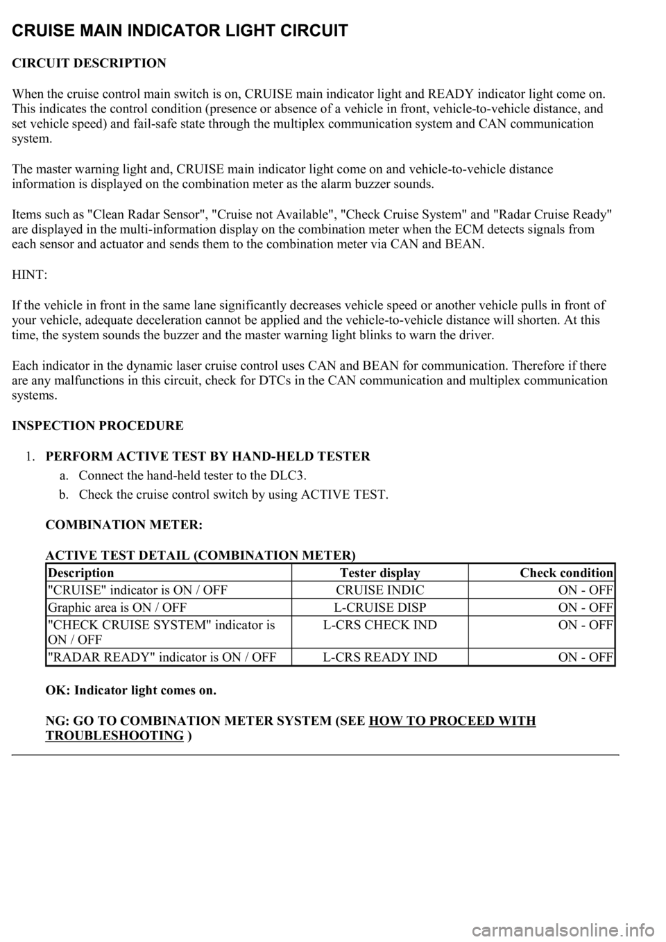
ACTIVE TEST DETAIL (COMBINATION METER)
OK: Indicator light comes on.
NG: GO TO COMBINATION METER SYSTEM (SEE HOW TO PROCEED WITH
TROUBLESHOOTING )
DescriptionTester displayCheck condition
"CRUISE" indicator is ON / OFFCRUISE INDICON - OFF
Graphic area is ON / OFFL-CRUISE DISPON - OFF
"CHECK CRUISE SYSTEM" indicator is
ON / OFFL-CRS CHECK INDON - OFF
"RADAR READY" indicator is ON / OFFL-CRS READY INDON - OFF
Page 2521 of 4500
malfunctions in this circuit, check for DTCs in the CAN communication and multiplex communication systems.
When the wiper is in the LO or HI mode, the dynamic laser cruise control is automatically cancelled and goes
into the standby mode. (In INT (intermittent operation) mode, the laser cruise control is not cancelled.)
INSPECTION PROCEDURE
1.INSPECT WIPER AND WASHER SYSTEM (SEE INSPECTION
)
OK:
Wiper function is normal.
NG: GO TO WIPER AND WASHER SYSTEM (SEE HOW TO PROCEED WITH
TROUBLESHOOTING )
OK: PROCEED TO NEXT CIRCUIT INSPECTION SHOWN IN DIAGNOSTIC TROUBLE
CODE CHART
CIRCUIT DESCRIPTION
This circuit outputs trouble codes on the multi-information display in the combination meter when terminals TC
and CG of the DLC3 are connected.
WIRING DIAGRAM
Fig. 84: Wiring Diagram
- Diagnosis Circuit
Page 2533 of 4500
Fig. 6: Dynamic Radar Cruise Control System Cruise Control Example Chart
Courtesy of TOYOTA MOTOR SALES, U.S.A., INC.
Setting of the vehicle distance can be changed to 3 distances by operating the distance control
switch (DISP2 button): long (approximately 75 m (246 ft)), middle (approximately 50 m (164 ft)),
and short (approximately 30 m (98 ft)) when vehicle speed is approximately 90 km/h (55 mph).
HINT:
Vehicle distance increases and decreases in accordance with vehicle speed.
Controlling condition is indicated on the multi-information display in the combination meter.
2.FUNCTION OF MAIN COMPONENTS
Page 2549 of 4500
Fig. 17: [Display NORM]
Courtesy of TOYOTA MOTOR SALES, U.S.A., INC.
3.INSPECT STEERING PAD SWITCH ASSY
a. Turn the ignition switch to the ON position.
b. Push on the ON-OFF button of the cruise control main switch.
c. Push on the distance control switch (DISP2) of the steering pad switch.
d. Check that the indication of vehicle-to-vehicle distance, which is shown in the multi-information
displa
y on the combination meter, changes from "LONG", "MIDDLE" to "SHORT" in that order.
Page 2550 of 4500
Fig. 18: Multi-Information Display Chart On Combination Meter
Courtesy of TOYOTA MOTOR SALES, U.S.A., INC.
HINT:
The indication is immediately set to "LONG" each time the engine is started.
If a normal system code is displayed during the DTC check but the problem still occurs, check the suspected
areas for each problem symptom in the order given in the table below and proceed to the relevant
troubleshooting page.
HINT:
Inspect the "Fuse" and "Relay" before confirming the suspected areas as shown in the Fig. 19
below. Inspect
each suspected area for the correspondin
g symptom in numerical order.
Page 2560 of 4500
Fig. 29: Identifying Blinking Pattern Of CRUISE Main Indicator Light
Courtesy of TOYOTA MOTOR SALES, U.S.A., INC.
2.DESCRIPTION
a. The ECM controls the dynamic radar cruise control system of the vehicle. The data and DTCs
relating to the dynamic radar cruise control system can be read from the DLC3 of the vehicle. If
either DTC or CRUISE OK is not displayed in the multi-information display on the combination
meter when checking for DTCs, there may be a problem with the combination meter or the CAN
communication and multiplex communication system.
Use the hand-held tester to check and solve the problem.
3.CHECK THE DLC3
a. The vehicle's ECM uses ISO 9141-2 for communication. The terminal arrangement of the DLC3
complies with SAE J1962 and matches the ISO 9141-2 format.
Page 2562 of 4500

tester to the DLC3, turned the ignition switch to the ON position and operated the tester, there is a
problem on either the vehicle side or the tool side.
If communication is normal when the tool is connected to another vehicle, inspect the DLC3 on the
original vehicle.
If communication is still impossible when the tool is connected to another vehicle, the problem is
probably in the tool itself, so consult the Service Department listed in the tool's instruction manual.
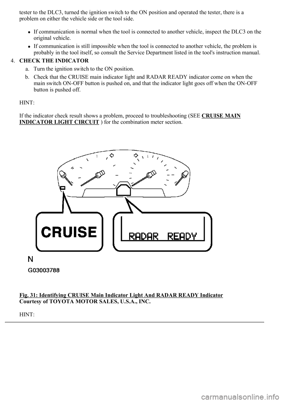
4.CHECK THE INDICATOR
a. Turn the ignition switch to the ON position.
b. Check that the CRUISE main indicator light and RADAR READY indicator come on when the
main switch ON-OFF button is pushed on, and that the indicator light goes off when the ON-OFF
button is pushed off.
HINT:
If the indicator check result shows a problem, proceed to troubleshooting (SEE CRUISE MAIN
INDICATOR LIGHT CIRCUIT ) for the combination meter section.
<0029004c004a0011000300160014001d0003002c0047004800510057004c0049005c004c0051004a0003002600350038002c00360028000300300044004c00510003002c00510047004c004600440057005200550003002f004c004a004b00570003002400
51004700030035002400270024003500030035002800240027[Y Indicator
Courtesy of TOYOTA MOTOR SALES, U.S.A., INC.
HINT: