2003 LEXUS LS430 Combination
[x] Cancel search: CombinationPage 2570 of 4500
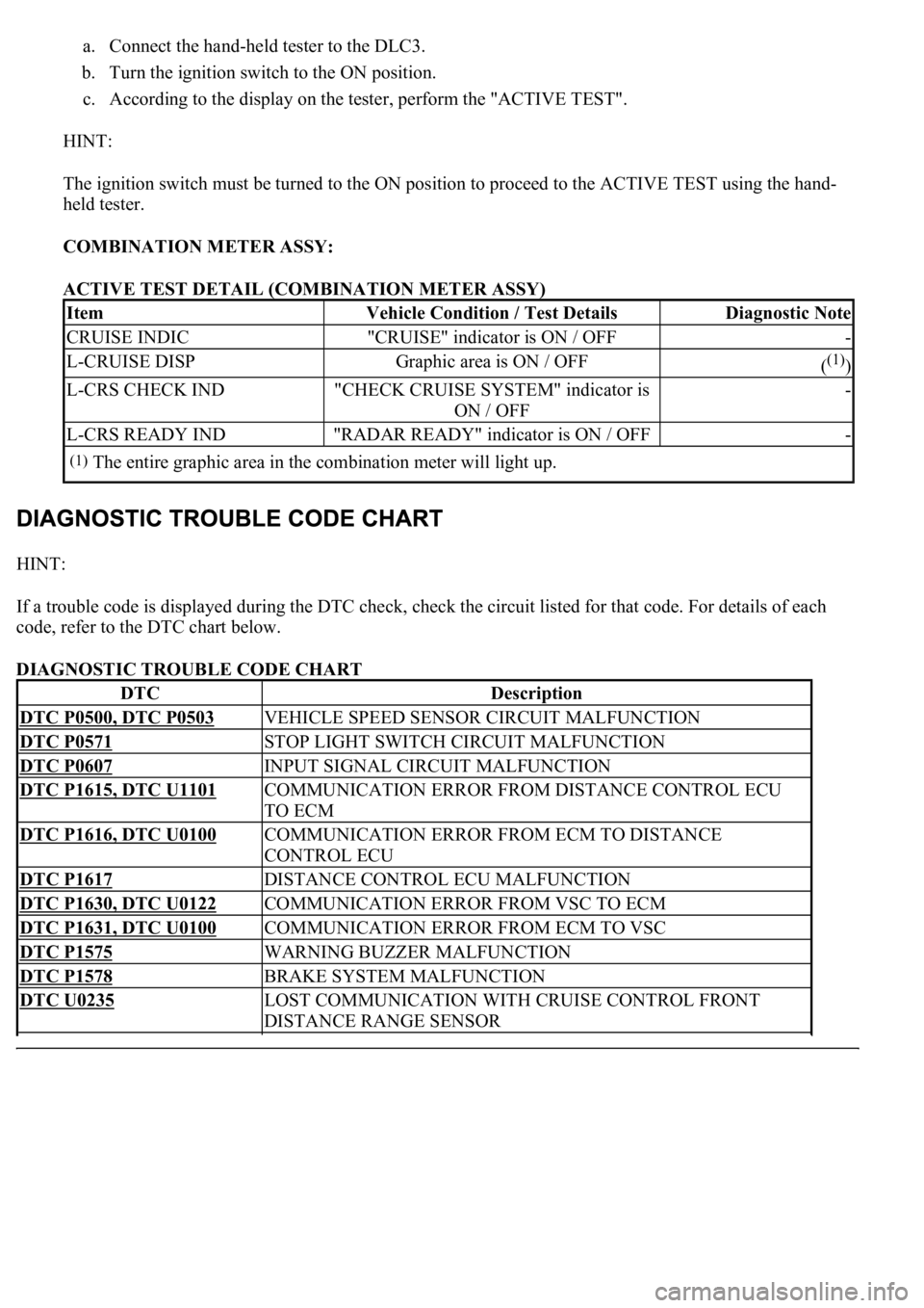
a. Connect the hand-held tester to the DLC3.
b. Turn the ignition switch to the ON position.
c. According to the display on the tester, perform the "ACTIVE TEST".
HINT:
The ignition switch must be turned to the ON position to proceed to the ACTIVE TEST using the hand-
held tester.
COMBINATION METER ASSY:
ACTIVE TEST DETAIL (COMBINATION METER ASSY)
HINT:
If a trouble code is displayed during the DTC check, check the circuit listed for that code. For details of each
code, refer to the DTC chart below.
DIAGNOSTIC TROUBLE CODE CHART
ItemVehicle Condition / Test DetailsDiagnostic Note
CRUISE INDIC"CRUISE" indicator is ON / OFF-
L-CRUISE DISPGraphic area is ON / OFF((1))
L-CRS CHECK IND"CHECK CRUISE SYSTEM" indicator is
ON / OFF-
L-CRS READY IND"RADAR READY" indicator is ON / OFF-
(1)The entire graphic area in the combination meter will light up.
DTCDescription
DTC P0500, DTC P0503VEHICLE SPEED SENSOR CIRCUIT MALFUNCTION
DTC P0571STOP LIGHT SWITCH CIRCUIT MALFUNCTION
DTC P0607INPUT SIGNAL CIRCUIT MALFUNCTION
DTC P1615, DTC U1101COMMUNICATION ERROR FROM DISTANCE CONTROL ECU
TO ECM
DTC P1616, DTC U0100COMMUNICATION ERROR FROM ECM TO DISTANCE
CONTROL ECU
DTC P1617DISTANCE CONTROL ECU MALFUNCTION
DTC P1630, DTC U0122COMMUNICATION ERROR FROM VSC TO ECM
DTC P1631, DTC U0100COMMUNICATION ERROR FROM ECM TO VSC
DTC P1575WARNING BUZZER MALFUNCTION
DTC P1578BRAKE SYSTEM MALFUNCTION
DTC U0235LOST COMMUNICATION WITH CRUISE CONTROL FRONT
DISTANCE RANGE SENSOR
Page 2620 of 4500
CIRCUIT DESCRIPTION
When the cruise control main switch is on, CRUISE main indicator light and READY indicator light come on.
This indicates the control condition (presence or absence of a vehicle in front, vehicle-to-vehicle distance, and
set vehicle speed) and fail-safe state through the multiplex communication system and CAN communication
system.
The master warning light and CRUISE main indicator light come on and vehicle-to-vehicle distance
information is displayed on the combination meter as the alarm buzzer sounds.
Items such as "Clean Radar Sensor", "Cruise not Available", "Check Cruise System" and "Radar Cruise Ready"
are displayed in the multi-information display on the combination meter when the ECM detects signals from
each sensor and actuator and sends them to the combination meter via CAN and BEAN.
HINT:
If the vehicle in front in the same lane significantly decreases vehicle speed or another vehicle pulls in front of
your vehicle, adequate deceleration cannot be applied and the vehicle-to-vehicle distance will shorten. At this
time, the system sounds the buzzer and the master warning light blinks to warn the driver.
Each indicator in the dynamic laser cruise control uses CAN and BEAN for communication. Therefore if there
are any malfunctions in this circuit, check for DTCs in the CAN communication and multiplex communication
systems.
INSPECTION PROCEDURE
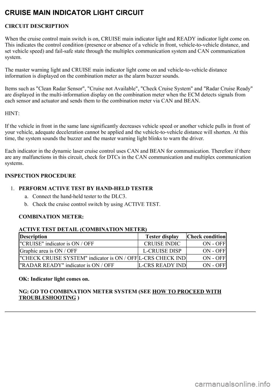
1.PERFORM ACTIVE TEST BY HAND-HELD TESTER
a. Connect the hand-held tester to the DLC3.
b. Check the cruise control switch by using ACTIVE TEST.
COMBINATION METER:
ACTIVE TEST DETAIL (COMBINATION METER)
OK: Indicator light comes on.
NG: GO TO COMBINATION METER SYSTEM (SEE HOW TO PROCEED WITH
TROUBLESHOOTING )
DescriptionTester displayCheck condition
"CRUISE" indicator is ON / OFFCRUISE INDICON - OFF
Graphic area is ON / OFFL-CRUISE DISPON - OFF
"CHECK CRUISE SYSTEM" indicator is ON / OFFL-CRS CHECK INDON - OFF
"RADAR READY" indicator is ON / OFFL-CRS READY INDON - OFF
Page 2622 of 4500
A wiper switch signal is sent to the distance control ECU via CAN and BEAN. Therefore if there are any
malfunctions in this circuit, check for DTCs in the CAN communication and multiplex communication systems.
When the wiper is in the HI mode, the dynamic radar cruise control is automatically cancelled and goes into the
standby mode.
INSPECTION PROCEDURE
1.INSPECT WIPER AND WASHER SYSTEM (SEE INSPECTION
)
OK:
Wiper function is normal.
NG: GO TO WIPER AND WASHER SYSTEM (SEE HOW TO PROCEED WITH
TROUBLESHOOTING )
OK: PROCEED TO NEXT CIRCUIT INSPECTION SHOWN IN DIAGNOSTIC TROUBLE
CODE CHART
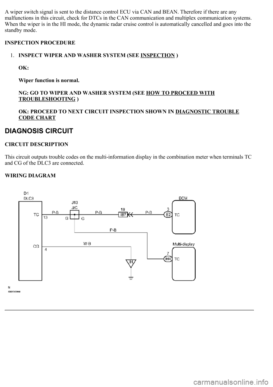
CIRCUIT DESCRIPTION
This circuit outputs trouble codes on the multi-information display in the combination meter when terminals TC
and CG of the DLC3 are connected.
WIRING DIAGRAM
Page 2680 of 4500
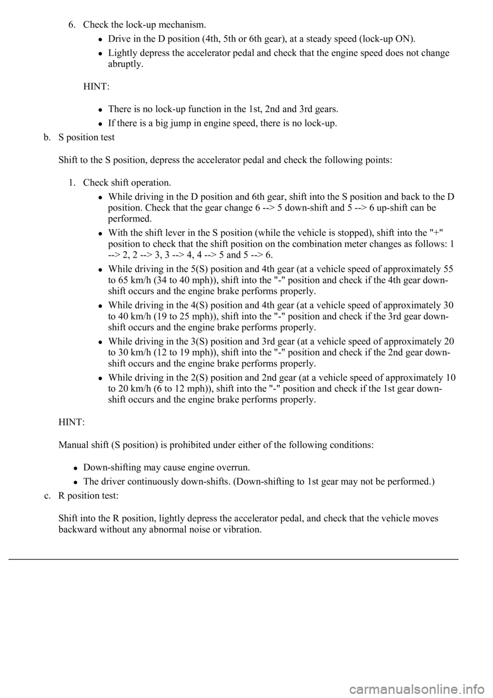
6. Check the lock-up mechanism.
Drive in the D position (4th, 5th or 6th gear), at a steady speed (lock-up ON).
Lightly depress the accelerator pedal and check that the engine speed does not change
abruptly.
HINT:
There is no lock-up function in the 1st, 2nd and 3rd gears.
If there is a big jump in engine speed, there is no lock-up.
b. S position test
Shift to the S position, depress the accelerator pedal and check the following points:
1. Check shift operation.
While driving in the D position and 6th gear, shift into the S position and back to the D
position. Check that the gear change 6 --> 5 down-shift and 5 --> 6 up-shift can be
performed.
With the shift lever in the S position (while the vehicle is stopped), shift into the "+"
position to check that the shift position on the combination meter changes as follows: 1
--> 2, 2 --> 3, 3 --> 4, 4 --> 5 and 5 --> 6.
While driving in the 5(S) position and 4th gear (at a vehicle speed of approximately 55
to 65 km/h (34 to 40 mph)), shift into the "-" position and check if the 4th gear down-
shift occurs and the engine brake performs properly.
While driving in the 4(S) position and 4th gear (at a vehicle speed of approximately 30
to 40 km/h (19 to 25 mph)), shift into the "-" position and check if the 3rd gear down-
shift occurs and the engine brake performs properly.
While driving in the 3(S) position and 3rd gear (at a vehicle speed of approximately 20
to 30 km/h (12 to 19 mph)), shift into the "-" position and check if the 2nd gear down-
shift occurs and the engine brake performs properly.
<003a004b004c004f0048000300470055004c0059004c0051004a0003004c005100030057004b004800030015000b0036000c0003005300520056004c0057004c00520051000300440051004700030015005100470003004a0048004400550003000b004400
5700030044000300590048004b004c0046004f004800030056[peed of approximately 10
to 20 km/h (6 to 12 mph)), shift into the "-" position and check if the 1st gear down-
shift occurs and the engine brake performs properly.
HINT:
Manual shift (S position) is prohibited under either of the following conditions:
Down-shifting may cause engine overrun.
The driver continuously down-shifts. (Down-shifting to 1st gear may not be performed.)
c. R position test:
Shift into the R position, lightly depress the accelerator pedal, and check that the vehicle moves
backward without any abnormal noise or vibration.
Page 2769 of 4500
OK:
Gear position changes in accordance with the tester command
NG: REPAIR OR REPLACE TRANSMISSION VALVE BODY ASSY (See step 6 on
REPLACEMENT
)
OK: Go to next step
3.CLEAR THE DTC AND RUNNING TEST
a. Clear the DTC, and check DTC again after conducting the "MONITOR DRIVE PATTERN FOR
ECT TEST" (see MONITOR DRIVE PATTERN
).
OK:
No DTC code
NG: REPAIR OR REPLACE TRANSMISSION VALVE BODY ASSY (See step 6 on
REPLACEMENT
)
OK: END
DTC P0748: PRESSURE CONTROL SOLENOID "A" ELECTRICAL (SHIFT SOLENOID VALVE
SL1)
CIRCUIT DESCRIPTION
Shifting from 1st to 6th is performed in combination with "ON" and "OFF" operation of the shift solenoid
valves SL1, SL2, S1, S2, S3, S4 and SR which is controlled by the ECM. If an open or short circuit occurs in
either of the shift solenoid valves, the ECM controls the remaining normal shift solenoid valve to allow the
vehicle to be operated smoothly (see FAIL
-SAFE CHART ).
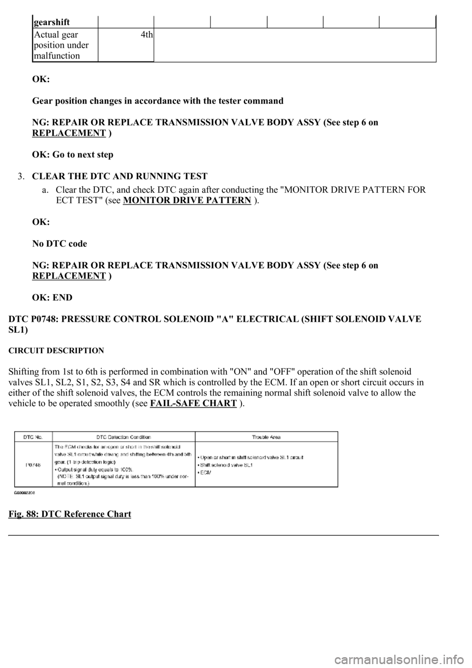
Fig. 88: DTC Reference Chart
gearshift
Actual gear
position under
malfunction4th
Page 2811 of 4500
NG: REPLACE SHIFT SOLENOID VALVE (SL2)
OK: Go to next step
5.INSPECT TRANSMISSION VALVE BODY ASSY (See chapter 2 in PROBLEM SYMPTOMS
TABLE )
OK:
There are no foreign objects on each valve and they operate smoothly.
NG: REPAIR OR REPLACE TRANSMISSION VALVE BODY ASSY (See step 6 on
REPLACEMENT
)
OK: Go to next step
6.INSPECT TORQUE CONVERTER CLUTCH ASSY (See INSPECTION
)
OK:
The torque converter clutch operates normally.
NG: REPLACE TORQUE CONVERTER CLUTCH ASSY
OK: REPAIR OR REPLACE AUTOMATIC TRANSMISSION ASSY (See COMPONENTS
)
DTC P0778: PRESSURE CONTROL SOLENOID "B" ELECTRICAL (SHIFT SOLENOID VALVE
SL2)
CIRCUIT DESCRIPTION
Shifting from 1st to 6th is performed in combination with "ON" and "OFF" operation of the shift solenoid
valves SL1, SL2, S1, S2, S3, S4 and SR which is controlled by the ECM. If an open or short circuit occurs in
either of the shift solenoid valves, the ECM controls the remaining normal shift solenoid valve to allow the
vehicle to be operated smoothly (see FAIL
-SAFE CHART ).
Fig. 119: DTC Reference Chart
Courtesy of TOYOTA MOTOR SALES, U.S.A., INC.
MONITOR DESCRIPTION
Page 2827 of 4500
Shifting from 1st to 6th is performed in combination with "ON" and "OFF" operation of the shift solenoid
valves SL1, SL2, S1, S2, S3, S4 and SR which is controlled by the ECM. If an open or short circuit occurs in
either of the shift solenoid valves, the ECM controls the remaining normal shift solenoid valve to allow the
vehicle to be operated smoothly. (In case of an open or short circuit, the ECM stops sending current to the
circuit.) Fail safe function (see FAIL
-SAFE CHART ).
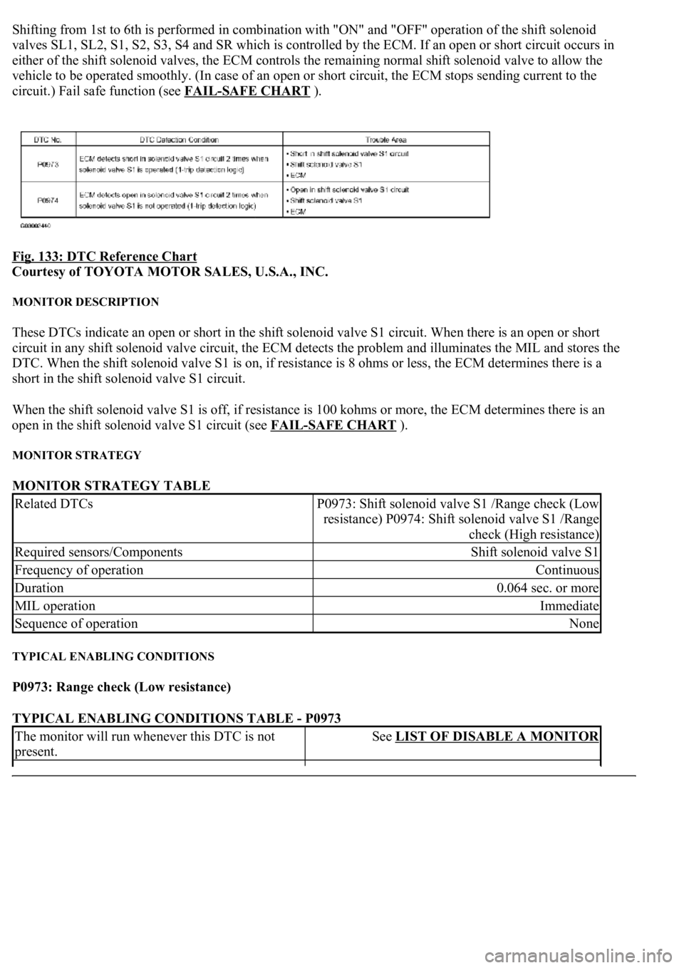
Fig. 133: DTC Reference Chart
Courtesy of TOYOTA MOTOR SALES, U.S.A., INC.
MONITOR DESCRIPTION
These DTCs indicate an open or short in the shift solenoid valve S1 circuit. When there is an open or short
circuit in any shift solenoid valve circuit, the ECM detects the problem and illuminates the MIL and stores the
DTC. When the shift solenoid valve S1 is on, if resistance is 8 ohms or less, the ECM determines there is a
short in the shift solenoid valve S1 circuit.
When the shift solenoid valve S1 is off, if resistance is 100 kohms or more, the ECM determines there is an
open in the shift solenoid valve S1 circuit (see FAIL
-SAFE CHART ).
MONITOR STRATEGY
MONITOR STRATEGY TABLE
TYPICAL ENABLING CONDITIONS
P0973: Range check (Low resistance)
TYPICAL ENABLING CONDITIONS TABLE - P0973
Related DTCsP0973: Shift solenoid valve S1 /Range check (Low
resistance) P0974: Shift solenoid valve S1 /Range
check (High resistance)
Required sensors/ComponentsShift solenoid valve S1
Frequency of operationContinuous
Duration0.064 sec. or more
MIL operationImmediate
Sequence of operationNone
The monitor will run whenever this DTC is not
present.See LIST OF DISABLE A MONITOR
Page 2832 of 4500
CIRCUIT DESCRIPTION
Shifting from 1st to 6th is performed in combination with "ON" and "OFF" operation of the shift solenoid
valves SL1, SL2, S1, S2, S3, S4 and SR which is controlled by the ECM. If an open or short circuit occurs in
either of the shift solenoid valves, the ECM controls the remaining normal shift solenoid valve to allow the
vehicle to be operated smoothly. (In case of an open or short circuit, the ECM stops sending current to the
circuit.) Fail safe function (see FAIL
-SAFE CHART ).
Fig. 138: DTC Reference Chart
Courtesy of TOYOTA MOTOR SALES, U.S.A., INC.
MONITOR DESCRIPTION
These DTCs indicate an open or short in the shift solenoid valve S2 circuit. When there is an open or short
circuit in any shift solenoid valve circuit, the ECM detects the problem and illuminates the MIL and stores the
DTC. When the shift solenoid valve S2 is on, if resistance is 8ohms or less, the ECM determines there is a short
in the shift solenoid valve S2 circuit.
When the shift solenoid valve S2 is off, if resistance is 100 kohms or more, the ECM determines there is an
open in the shift solenoid valve S2 circuit (see FAIL
-SAFE CHART ).
MONITOR STRATEGY
MONITOR STRATEGY TABLE
TYPICAL ENABLING CONDITIONS
P0976: Range check (Low resistance)
TYPICAL ENABLING CONDITIONS TABLE - P0976
Related DTCsP0976: Shift solenoid valve S2/Range check (Low
resistance) P0977: Shift solenoid valve S2/Range
check (High resistance)
Required sensors/ComponentsShift solenoid valve S2
Frequency of operationContinuous
Duration0.064 sec. or more
MIL operationImmediate
Sequence of operationNone