Page 2570 of 4500
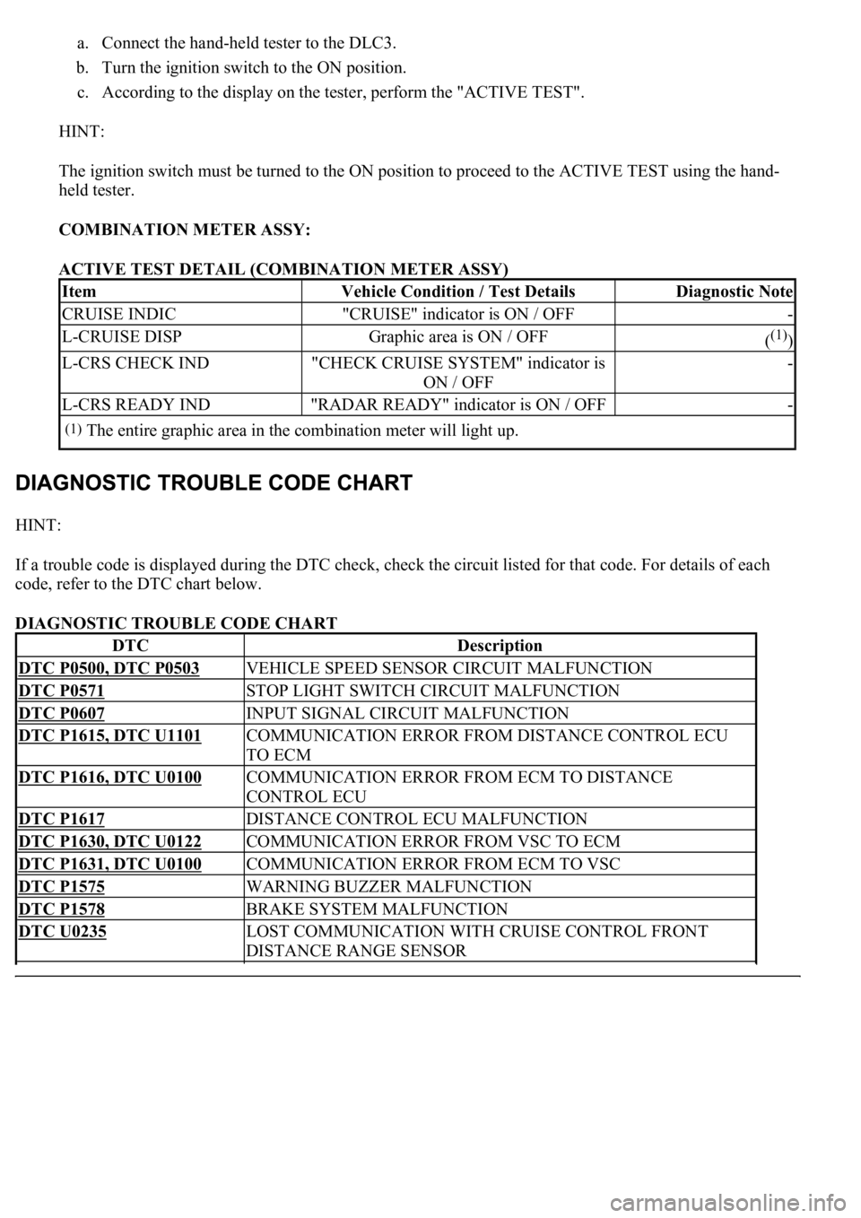
a. Connect the hand-held tester to the DLC3.
b. Turn the ignition switch to the ON position.
c. According to the display on the tester, perform the "ACTIVE TEST".
HINT:
The ignition switch must be turned to the ON position to proceed to the ACTIVE TEST using the hand-
held tester.
COMBINATION METER ASSY:
ACTIVE TEST DETAIL (COMBINATION METER ASSY)
HINT:
If a trouble code is displayed during the DTC check, check the circuit listed for that code. For details of each
code, refer to the DTC chart below.
DIAGNOSTIC TROUBLE CODE CHART
ItemVehicle Condition / Test DetailsDiagnostic Note
CRUISE INDIC"CRUISE" indicator is ON / OFF-
L-CRUISE DISPGraphic area is ON / OFF((1))
L-CRS CHECK IND"CHECK CRUISE SYSTEM" indicator is
ON / OFF-
L-CRS READY IND"RADAR READY" indicator is ON / OFF-
(1)The entire graphic area in the combination meter will light up.
DTCDescription
DTC P0500, DTC P0503VEHICLE SPEED SENSOR CIRCUIT MALFUNCTION
DTC P0571STOP LIGHT SWITCH CIRCUIT MALFUNCTION
DTC P0607INPUT SIGNAL CIRCUIT MALFUNCTION
DTC P1615, DTC U1101COMMUNICATION ERROR FROM DISTANCE CONTROL ECU
TO ECM
DTC P1616, DTC U0100COMMUNICATION ERROR FROM ECM TO DISTANCE
CONTROL ECU
DTC P1617DISTANCE CONTROL ECU MALFUNCTION
DTC P1630, DTC U0122COMMUNICATION ERROR FROM VSC TO ECM
DTC P1631, DTC U0100COMMUNICATION ERROR FROM ECM TO VSC
DTC P1575WARNING BUZZER MALFUNCTION
DTC P1578BRAKE SYSTEM MALFUNCTION
DTC U0235LOST COMMUNICATION WITH CRUISE CONTROL FRONT
DISTANCE RANGE SENSOR
Page 2588 of 4500
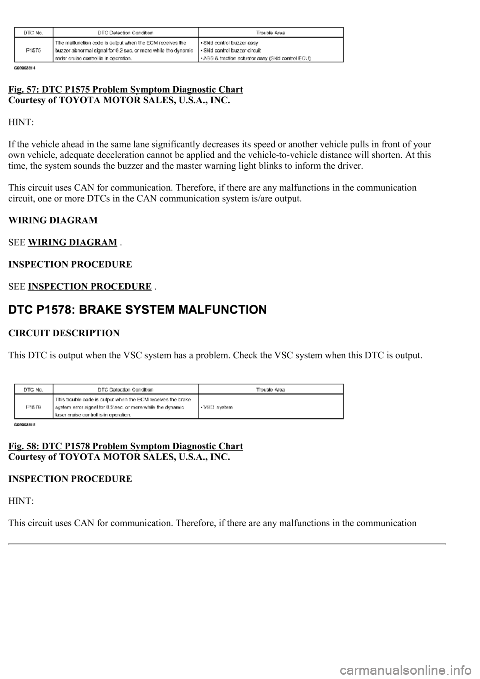
Fig. 57: DTC P1575 Problem Symptom Diagnostic Chart
Courtesy of TOYOTA MOTOR SALES, U.S.A., INC.
HINT:
If the vehicle ahead in the same lane significantly decreases its speed or another vehicle pulls in front of your
own vehicle, adequate deceleration cannot be applied and the vehicle-to-vehicle distance will shorten. At this
time, the system sounds the buzzer and the master warning light blinks to inform the driver.
This circuit uses CAN for communication. Therefore, if there are any malfunctions in the communication
circuit, one or more DTCs in the CAN communication system is/are output.
WIRING DIAGRAM
SEE WIRING DIAGRAM
.
INSPECTION PROCEDURE
SEE INSPECTION PROCEDURE
.
CIRCUIT DESCRIPTION
This DTC is output when the VSC system has a problem. Check the VSC system when this DTC is output.
Fig. 58: DTC P1578 Problem Symptom Diagnostic Chart
Courtesy of TOYOTA MOTOR SALES, U.S.A., INC.
INSPECTION PROCEDURE
HINT:
This circuit uses CAN for communication. Therefore, if there are an
y malfunctions in the communication
Page 2620 of 4500
CIRCUIT DESCRIPTION
When the cruise control main switch is on, CRUISE main indicator light and READY indicator light come on.
This indicates the control condition (presence or absence of a vehicle in front, vehicle-to-vehicle distance, and
set vehicle speed) and fail-safe state through the multiplex communication system and CAN communication
system.
The master warning light and CRUISE main indicator light come on and vehicle-to-vehicle distance
information is displayed on the combination meter as the alarm buzzer sounds.
Items such as "Clean Radar Sensor", "Cruise not Available", "Check Cruise System" and "Radar Cruise Ready"
are displayed in the multi-information display on the combination meter when the ECM detects signals from
each sensor and actuator and sends them to the combination meter via CAN and BEAN.
HINT:
If the vehicle in front in the same lane significantly decreases vehicle speed or another vehicle pulls in front of
your vehicle, adequate deceleration cannot be applied and the vehicle-to-vehicle distance will shorten. At this
time, the system sounds the buzzer and the master warning light blinks to warn the driver.
Each indicator in the dynamic laser cruise control uses CAN and BEAN for communication. Therefore if there
are any malfunctions in this circuit, check for DTCs in the CAN communication and multiplex communication
systems.
INSPECTION PROCEDURE
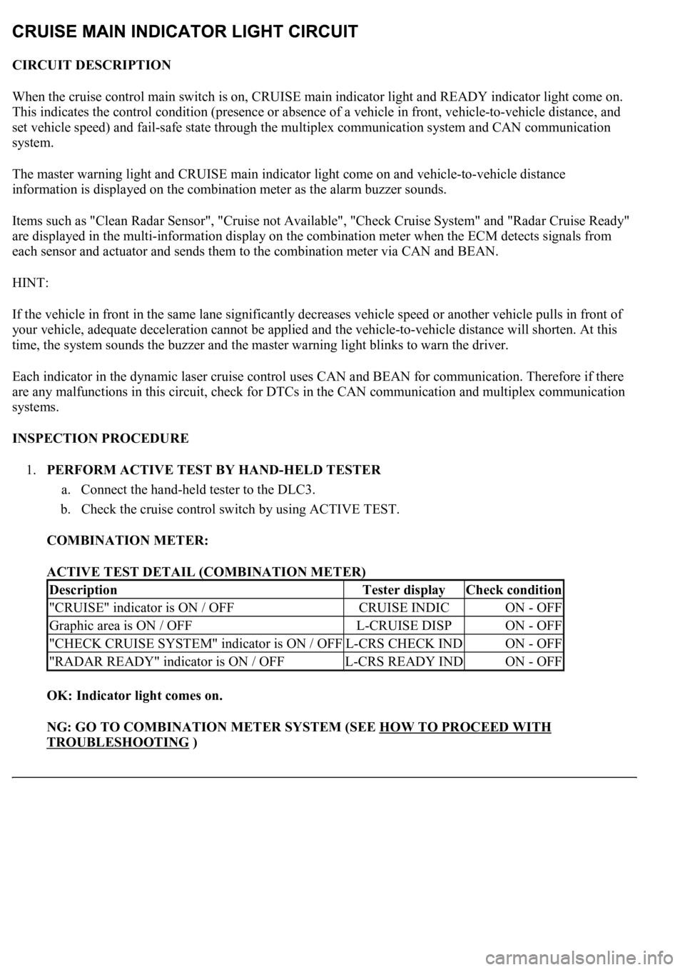
1.PERFORM ACTIVE TEST BY HAND-HELD TESTER
a. Connect the hand-held tester to the DLC3.
b. Check the cruise control switch by using ACTIVE TEST.
COMBINATION METER:
ACTIVE TEST DETAIL (COMBINATION METER)
OK: Indicator light comes on.
NG: GO TO COMBINATION METER SYSTEM (SEE HOW TO PROCEED WITH
TROUBLESHOOTING )
DescriptionTester displayCheck condition
"CRUISE" indicator is ON / OFFCRUISE INDICON - OFF
Graphic area is ON / OFFL-CRUISE DISPON - OFF
"CHECK CRUISE SYSTEM" indicator is ON / OFFL-CRS CHECK INDON - OFF
"RADAR READY" indicator is ON / OFFL-CRS READY INDON - OFF
Page 2623 of 4500
Fig. 89: Wiring Diagram - Diagnosis Circuit
Courtesy of TOYOTA MOTOR SALES, U.S.A., INC.
HINT:
When a particular warning light stays blinking, a ground short in the wiring of terminal TC of the DLC3 or an
internal ground short in the relevant ECU is suspected.
INSPECTION PROCEDURE
1.CHECK HARNESS AND CONNECTOR (TC of DLC3 - ECM)
a. Disconnect the E2 connector from the ECM.
b. Measure the resistance according to the value(s) in the table below.
Standard:
ECM CONNECTOR TERMINALS RESISTANCE
Fig. 90: Identifying DLC3 Connector (TC) Terminals
Courtesy of TOYOTA MOTOR SALES, U.S.A., INC.
Tester connectionConditionSpecified condition
TC (E2-3) - TC (D1 - 13)AlwaysBelow 1 ohms
Page 2627 of 4500
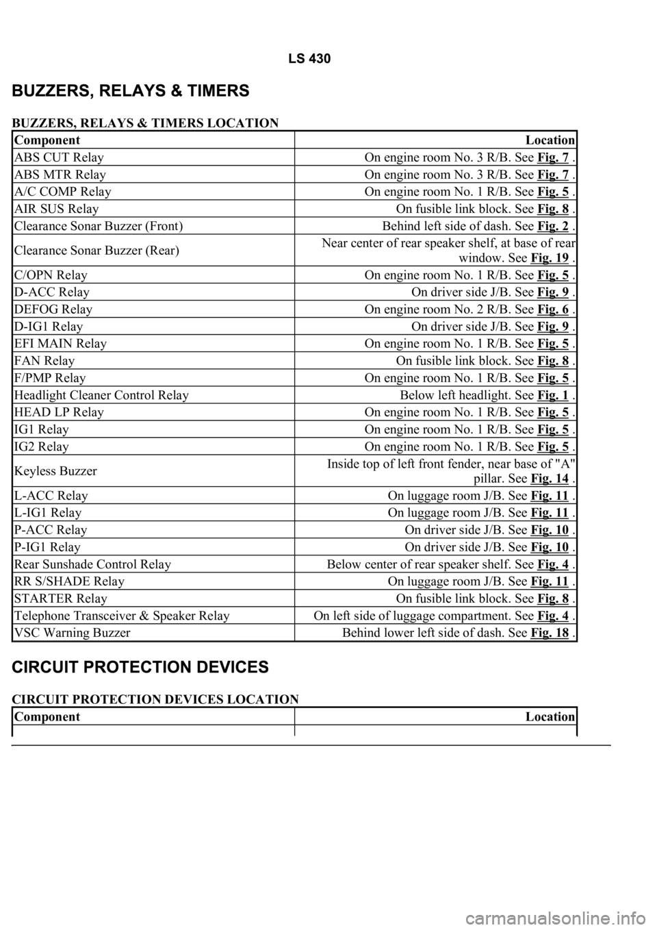
BUZZERS, RELAYS & TIMERS LOCATION
CIRCUIT PROTECTION DEVICES LOCATION
ComponentLocation
ABS CUT RelayOn engine room No. 3 R/B. See Fig. 7 .
ABS MTR RelayOn engine room No. 3 R/B. See Fig. 7 .
A/C COMP RelayOn engine room No. 1 R/B. See Fig. 5 .
AIR SUS RelayOn fusible link block. See Fig. 8 .
Clearance Sonar Buzzer (Front)Behind left side of dash. See Fig. 2 .
Clearance Sonar Buzzer (Rear)Near center of rear speaker shelf, at base of rear
window. See Fig. 19
.
C/OPN RelayOn engine room No. 1 R/B. See Fig. 5 .
D-ACC RelayOn driver side J/B. See Fig. 9 .
DEFOG RelayOn engine room No. 2 R/B. See Fig. 6 .
D-IG1 RelayOn driver side J/B. See Fig. 9 .
EFI MAIN RelayOn engine room No. 1 R/B. See Fig. 5 .
FAN RelayOn fusible link block. See Fig. 8 .
F/PMP RelayOn engine room No. 1 R/B. See Fig. 5 .
Headlight Cleaner Control RelayBelow left headlight. See Fig. 1 .
HEAD LP RelayOn engine room No. 1 R/B. See Fig. 5 .
IG1 RelayOn engine room No. 1 R/B. See Fig. 5 .
IG2 RelayOn engine room No. 1 R/B. See Fig. 5 .
Keyless BuzzerInside top of left front fender, near base of "A"
pillar. See Fig. 14
.
L-ACC RelayOn luggage room J/B. See Fig. 11 .
L-IG1 RelayOn luggage room J/B. See Fig. 11 .
P-ACC RelayOn driver side J/B. See Fig. 10 .
P-IG1 RelayOn driver side J/B. See Fig. 10 .
Rear Sunshade Control RelayBelow center of rear speaker shelf. See Fig. 4 .
RR S/SHADE RelayOn luggage room J/B. See Fig. 11 .
STARTER RelayOn fusible link block. See Fig. 8 .
Telephone Transceiver & Speaker RelayOn left side of luggage compartment. See Fig. 4 .
VSC Warning BuzzerBehind lower left side of dash. See Fig. 18 .
ComponentLocation
Page 2634 of 4500
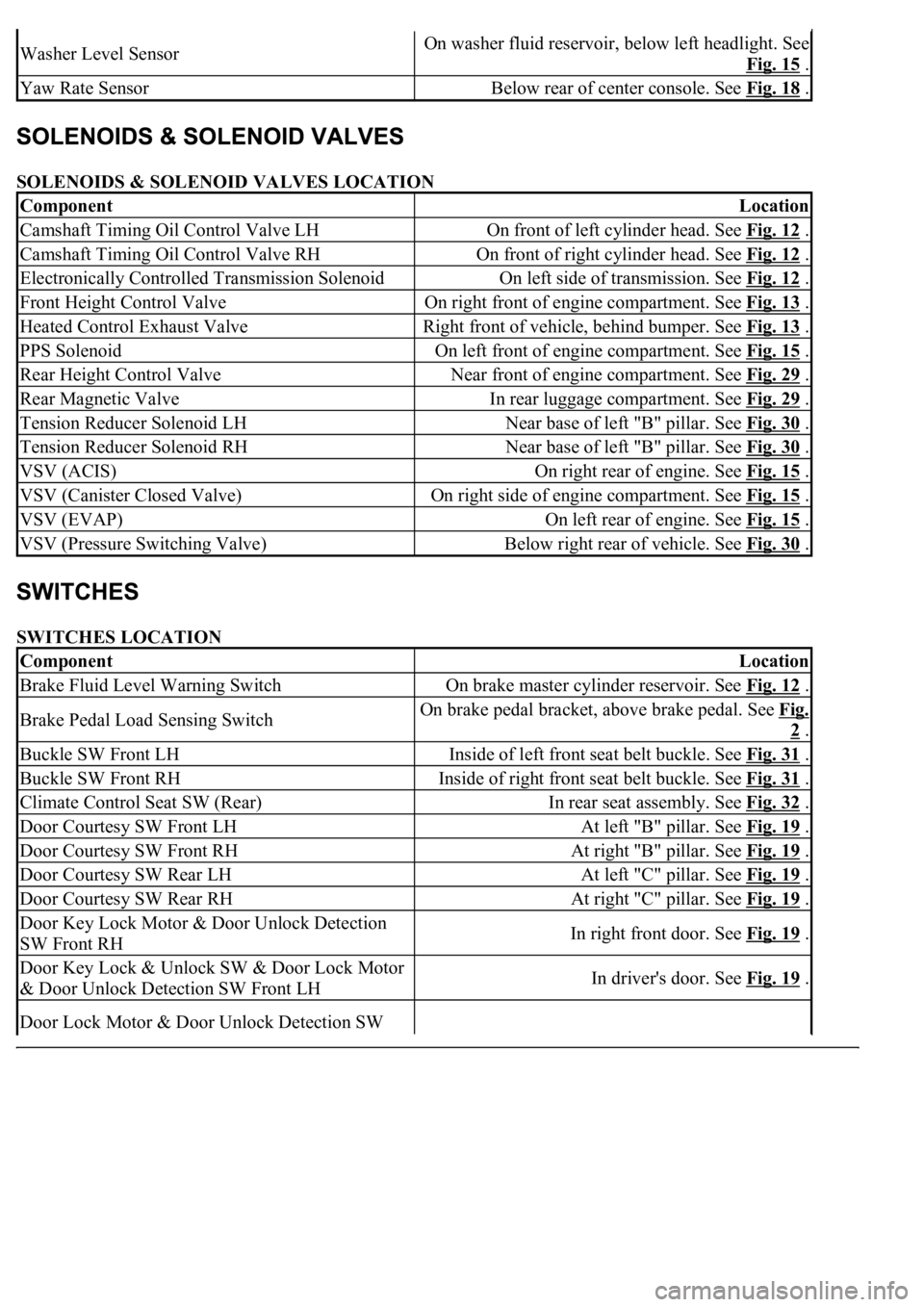
SOLENOIDS & SOLENOID VALVES LOCATION
SWITCHES LOCATION
Washer Level SensorOn washer fluid reservoir, below left headlight. See
Fig. 15
.
Yaw Rate SensorBelow rear of center console. See Fig. 18 .
ComponentLocation
Camshaft Timing Oil Control Valve LHOn front of left cylinder head. See Fig. 12 .
Camshaft Timing Oil Control Valve RHOn front of right cylinder head. See Fig. 12 .
Electronically Controlled Transmission SolenoidOn left side of transmission. See Fig. 12 .
Front Height Control ValveOn right front of engine compartment. See Fig. 13 .
Heated Control Exhaust ValveRight front of vehicle, behind bumper. See Fig. 13 .
PPS SolenoidOn left front of engine compartment. See Fig. 15 .
Rear Height Control ValveNear front of engine compartment. See Fig. 29 .
Rear Magnetic ValveIn rear luggage compartment. See Fig. 29 .
Tension Reducer Solenoid LHNear base of left "B" pillar. See Fig. 30 .
Tension Reducer Solenoid RHNear base of left "B" pillar. See Fig. 30 .
VSV (ACIS)On right rear of engine. See Fig. 15 .
VSV (Canister Closed Valve)On right side of engine compartment. See Fig. 15 .
VSV (EVAP)On left rear of engine. See Fig. 15 .
VSV (Pressure Switching Valve)Below right rear of vehicle. See Fig. 30 .
ComponentLocation
Brake Fluid Level Warning SwitchOn brake master cylinder reservoir. See Fig. 12 .
Brake Pedal Load Sensing SwitchOn brake pedal bracket, above brake pedal. See Fig.
2 .
Buckle SW Front LHInside of left front seat belt buckle. See Fig. 31 .
Buckle SW Front RHInside of right front seat belt buckle. See Fig. 31 .
Climate Control Seat SW (Rear)In rear seat assembly. See Fig. 32 .
Door Courtesy SW Front LHAt left "B" pillar. See Fig. 19 .
Door Courtesy SW Front RHAt right "B" pillar. See Fig. 19 .
Door Courtesy SW Rear LHAt left "C" pillar. See Fig. 19 .
Door Courtesy SW Rear RHAt right "C" pillar. See Fig. 19 .
Door Key Lock Motor & Door Unlock Detection
SW Front RHIn right front door. See Fig. 19 .
Door Key Lock & Unlock SW & Door Lock Motor
& Door Unlock Detection SW Front LHIn driver's door. See Fig. 19 .
Door Lock Motor & Door Unlock Detection SW
Page 3021 of 4500
Fig. 37: Taping Screwdriver Tip Before Use
Courtesy of TOYOTA MOTOR SALES, U.S.A., INC.
g. Adjust the striker position by slightly loosening the striker mounting screws and hitting the striker
with a plastic-faced hammer.
h. Tighten the striker mounting screws after the adjustment.
Torque: 23 N.m (235 kgf.cm, 17 ft.lbf)
i. Connect the negative (-) terminal cable to the battery.
j. Initialize both systems (see INITIALIZATION
).
k. Inspect the SRS warning lamp (see DIAGNOSIS SYSTEM
).
Page 3077 of 4500
Fig. 90: Removing Cover
Courtesy of TOYOTA MOTOR SALES, U.S.A., INC.
k. Adjust the striker position by slightly loosening the striker mounting screws and hitting the striker
with a plastic-faced hammer.
l. Tighten the striker mounting screws after the adjustment.
Torque: 23 N.m (235 kgf.cm, 17 ft.lbf)
m. Connect the negative (-) terminal cable to the battery.
n. Initialize both systems (see INITIALIZATION
).
o. Inspect the SRS warning lamp (see DIAGNOSIS SYSTEM
).