Page 2519 of 4500

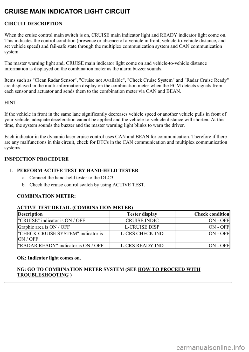
CIRCUIT DESCRIPTION
When the cruise control main switch is on, CRUISE main indicator light and READY indicator light come on.
This indicates the control condition (presence or absence of a vehicle in front, vehicle-to-vehicle distance, and
set vehicle speed) and fail-safe state through the multiplex communication system and CAN communication
system.
The master warning light and, CRUISE main indicator light come on and vehicle-to-vehicle distance
information is displayed on the combination meter as the alarm buzzer sounds.
Items such as "Clean Radar Sensor", "Cruise not Available", "Check Cruise System" and "Radar Cruise Ready"
are displayed in the multi-information display on the combination meter when the ECM detects signals from
each sensor and actuator and sends them to the combination meter via CAN and BEAN.
HINT:
If the vehicle in front in the same lane significantly decreases vehicle speed or another vehicle pulls in front of
your vehicle, adequate deceleration cannot be applied and the vehicle-to-vehicle distance will shorten. At this
time, the system sounds the buzzer and the master warning light blinks to warn the driver.
Each indicator in the dynamic laser cruise control uses CAN and BEAN for communication. Therefore if there
are any malfunctions in this circuit, check for DTCs in the CAN communication and multiplex communication
systems.
INSPECTION PROCEDURE
1.PERFORM ACTIVE TEST BY HAND-HELD TESTER
a. Connect the hand-held tester to the DLC3.
b. Check the cruise control switch by using ACTIVE TEST.
COMBINATION METER:
ACTIVE TEST DETAIL (COMBINATION METER)
OK: Indicator light comes on.
NG: GO TO COMBINATION METER SYSTEM (SEE HOW TO PROCEED WITH
TROUBLESHOOTING )
DescriptionTester displayCheck condition
"CRUISE" indicator is ON / OFFCRUISE INDICON - OFF
Graphic area is ON / OFFL-CRUISE DISPON - OFF
"CHECK CRUISE SYSTEM" indicator is
ON / OFFL-CRS CHECK INDON - OFF
"RADAR READY" indicator is ON / OFFL-CRS READY INDON - OFF
Page 2522 of 4500
Courtesy of TOYOTA MOTOR SALES, U.S.A., INC.
HINT:
When a particular warning light stays blinking, a ground short in the wiring of terminal TC of the DLC3 or an
internal ground short in the relevant ECU is suspected.
INSPECTION PROCEDURE
1.CHECK HARNESS AND CONNECTOR (TC of DLC3 - ECM)
a. Disconnect the E2 connector from the ECM.
b. Measure the resistance according to the value(s) in the table below.
Standard:
ECM CONNECTOR TERMINALS RESISTANCE SPECIFICATION
Fig. 85: Identifying DLC3 Connector (TC) Terminals
Courtesy of TOYOTA MOTOR SALES, U.S.A., INC.
Tester connectionConditionSpecified condition
TC (E2-3) - TC (D1 - 13)AlwaysBelow 1 ohms
Page 2526 of 4500

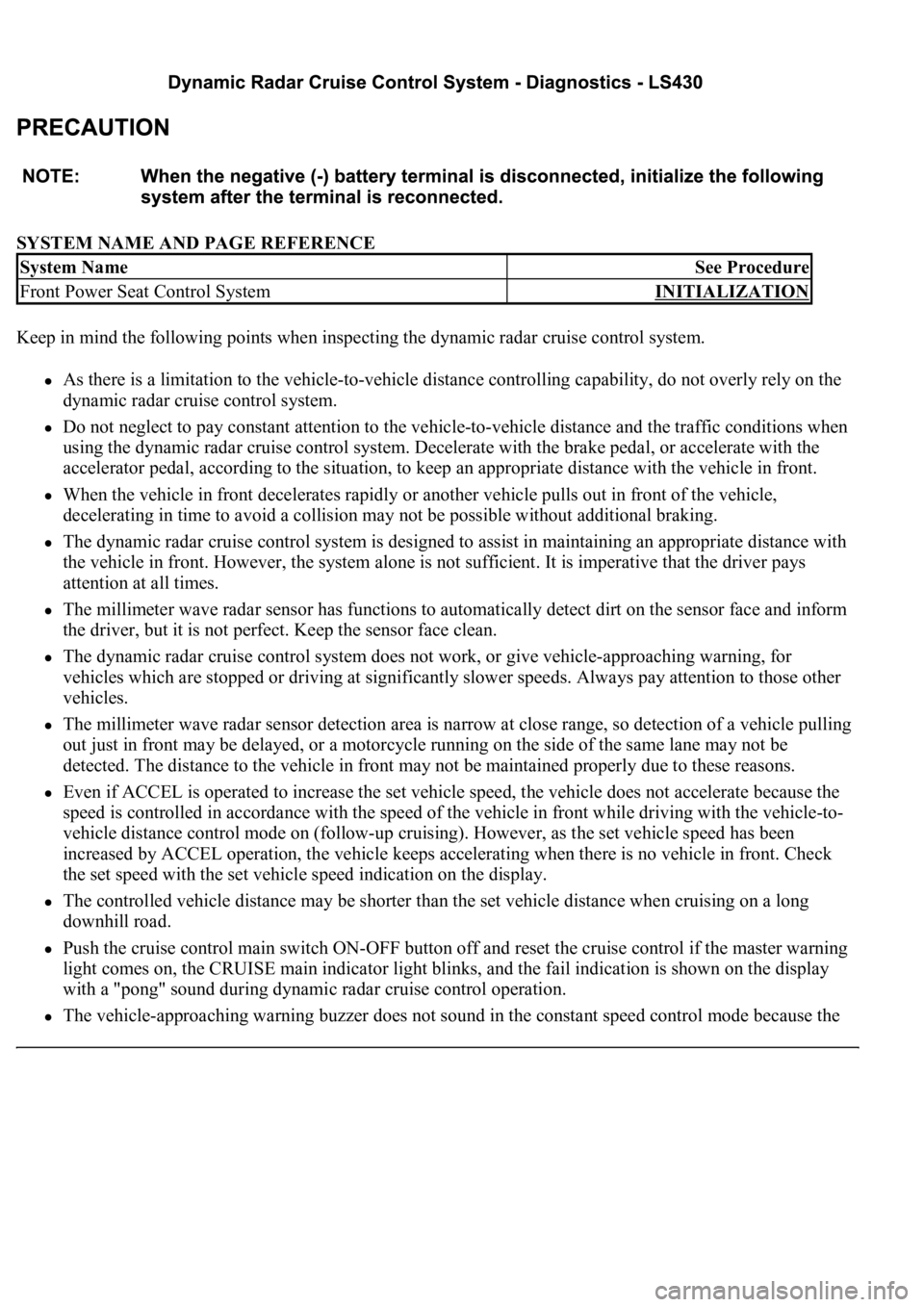
SYSTEM NAME AND PAGE REFERENCE
Keep in mind the following points when inspecting the dynamic radar cruise control system.
As there is a limitation to the vehicle-to-vehicle distance controlling capability, do not overly rely on the
dynamic radar cruise control system.
Do not neglect to pay constant attention to the vehicle-to-vehicle distance and the traffic conditions when
using the dynamic radar cruise control system. Decelerate with the brake pedal, or accelerate with the
accelerator pedal, according to the situation, to keep an appropriate distance with the vehicle in front.
When the vehicle in front decelerates rapidly or another vehicle pulls out in front of the vehicle,
decelerating in time to avoid a collision may not be possible without additional braking.
The dynamic radar cruise control system is designed to assist in maintaining an appropriate distance with
the vehicle in front. However, the system alone is not sufficient. It is imperative that the driver pays
attention at all times.
The millimeter wave radar sensor has functions to automatically detect dirt on the sensor face and inform
the driver, but it is not perfect. Keep the sensor face clean.
The dynamic radar cruise control system does not work, or give vehicle-approaching warning, for
vehicles which are stopped or driving at significantly slower speeds. Always pay attention to those other
vehicles.
The millimeter wave radar sensor detection area is narrow at close range, so detection of a vehicle pulling
out just in front may be delayed, or a motorcycle running on the side of the same lane may not be
detected. The distance to the vehicle in front may not be maintained properly due to these reasons.
Even if ACCEL is operated to increase the set vehicle speed, the vehicle does not accelerate because the
speed is controlled in accordance with the speed of the vehicle in front while driving with the vehicle-to-
vehicle distance control mode on (follow-up cruising). However, as the set vehicle speed has been
increased by ACCEL operation, the vehicle keeps accelerating when there is no vehicle in front. Check
the set speed with the set vehicle speed indication on the display.
The controlled vehicle distance may be shorter than the set vehicle distance when cruising on a long
downhill road.
Push the cruise control main switch ON-OFF button off and reset the cruise control if the master warning
light comes on, the CRUISE main indicator light blinks, and the fail indication is shown on the display
with a "pong" sound during dynamic radar cruise control operation.
The vehicle-approaching warning buzzer does not sound in the constant speed control mode because the
System NameSee Procedure
Front Power Seat Control SystemINITIALIZATION
Page 2558 of 4500
Fig. 27: Signal Waveform Graph (Waveform 2)
Courtesy of TOYOTA MOTOR SALES, U.S.A., INC.
1.DIAGNOSIS FUNCTION
a. The diagnosis function makes the master warning light and the multi-information display come on,
and the CRUISE main indicator light blinks as shown in the illustration. When a malfunction
occurs in the dynamic radar cruise control system, the DTCs are stored in the ECM.
Page 2559 of 4500
Fig. 28: Identifying Master Warning Light And CRUISE Main Indicator Light
Courtesy of TOYOTA MOTOR SALES, U.S.A., INC.
Page 2564 of 4500
Fig. 33: Connecting Hand-Held Tester To DLC3
Courtesy of TOYOTA MOTOR SALES, U.S.A., INC.
1.Constant speed control mode and vehicle-to-vehicle distance control mode:
If the following conditions are detected while the dynamic radar cruise control is in operation, the system
clears the stored vehicle speed in the ECM and cancels the dynamic radar cruise control operation.
Fig. 34: Identifying CRUISE Main Indicator Light And Master Warning Light
Page 2565 of 4500
Courtesy of TOYOTA MOTOR SALES, U.S.A., INC.
Fig. 35: Fail
-Safe Chart
Courtesy of TOYOTA MOTOR SALES, U.S.A., INC.
2.Only in the vehicle-to-vehicle distance control mode:
If the following conditions are detected while the dynamic radar cruise control is in operation, the system
clears the stored vehicle speed in the ECM and cancels the dynamic radar cruise control operation.
Fig. 36: Identifying CRUISE Main Indicator Light And Master Warning Light
Courtesy of TOYOTA MOTOR SALES, U.S.A., INC.
Fig. 37: Fail
-Safe Chart
Courtesy of TOYOTA MOTOR SALES, U.S.A., INC.
3.Only in the vehicle-to-vehicle distance control mode:
If the following conditions are detected while the dynamic radar cruise control is in operation, the system
maintains the stored vehicle speed in the ECM and cancels the d
ynamic radar cruise control operation.
Page 2566 of 4500
Fig. 38: Identifying CRUISE Main Indicator Light And Master Warning Light
Courtesy of TOYOTA MOTOR SALES, U.S.A., INC.
Fig. 39: Fail
-Safe Chart (1 Of 2)
Courtesy of TOYOTA MOTOR SALES, U.S.A., INC.
4.Constant speed control mode and vehicle-to-vehicle distance control mode:
If the following conditions are detected while the dynamic radar cruise control is in operation, the system
clears the stored vehicle speed and cancels the dynamic radar cruise control operation.
HINT:
In the vehicle-to-vehicle distance control mode, the stored vehicle speed in the ECM is maintained.
Fig. 40: Fail
-Safe Chart (2 Of 2)
Courtesy of TOYOTA MOTOR SALES, U.S.A., INC.