Page 495 of 4500

Fig. 17: Diagnostic Trouble Code Information Chart (2 Of 2)
Courtesy of TOYOTA MOTOR SALES, U.S.A., INC.
*1: For codes in the "Indicator Light" column with a "circ" mark, the absorber control indicator lamp blinks at 1
second intervals.
*2: For codes in the "Indicator Light" column with a " (xcirc)" mark, when trouble occurs, "HEIGHT HI" is
displayed on the multi-information display. Also, the master warning light is lit on the combination meter and
an alarm sounds.
*3: Since the relief pressure of the compressed air is 980 kPa (10 kgf/cm
2 , 142 psi), if vehicle height control is
attempted on a steeply sloping road, when the vehicle is overloaded, or when the vehicle height is jacked up
with the engine running, code "C1751" may be output and vehicle height control may be suspended. (This is not
abnormal.) In this case, however, when detecting the first error, approximately 10 minutes after the ignition
switch was turned to the ON position, vehicle height control is resumed. When the following errors are
detected, it takes 70 minutes until the control is resumed.
*4: If vehicle height control is operated while the wheels are removed or the vehicle is jacked up, code "C1752"
may be output, but this is not abnormal. When code "C1752" is output, vehicle height control is not carried out.
However, control is resumed if the ignition switch is turned off, then to the ON position again.
CIRCUIT DESCRIPTION
The height control sensor sub-assy controls the resistance value by following changes in vehicle height. The
suspension control ECU detects the change in vehicle height from the transformed voltage. The suspension
control ECU outputs a constant voltage of 5 V to the SHB terminal of the height control sensor sub-assy.
In the height control sensor, the voltage is changed due to resistance. The changed voltage is output from the
Page 679 of 4500
Fig. 41: Removing Screws
Courtesy of TOYOTA MOTOR SALES, U.S.A., INC.
5.INSTALL HORN BUTTON ASSY (See step 6 on REPLACEMENT
)
6.INSPECT HORN BUTTON ASSY (See ON
-VEHICLE INSPECTION )
7.SRS WARNING LIGHT (See DIAGNOSIS SYSTEM
)
REPLACEMENT
HINT:
See COMPONENTS - FRONT BUMPER , COMPONENTS - REAR BUMPER .
See LOCATION .
Installation is in the reverse order of removal.
1.REMOVE FRONT BUMPER COVER (See step 5 on REPLACEMENT
)
2.REMOVE REAR BUMPER COVER (See step 12 on REPLACEMENT
)
Page 838 of 4500

<0029004c004a001100030014001c001d00030026005200510051004800460057004c0051004a00030029004f00520052005500030036004b004c004900570003002a00480044005500030036004b004c00490057004c0051004a0003003500520047000300
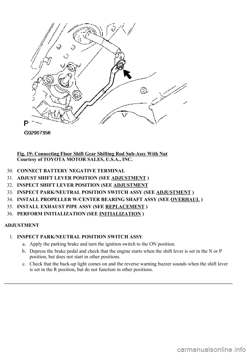
3600580045[-Assy With Nut
Courtesy of TOYOTA MOTOR SALES, U.S.A., INC.
30.CONNECT BATTERY NEGATIVE TERMINAL
31.ADJUST SHIFT LEVER POSITION (SEE ADJUSTMENT
)
32.INSPECT SHIFT LEVER POSITION (SEE ADJUSTMENT
33.INSPECT PARK/NEUTRAL POSITION SWITCH ASSY (SEE ADJUSTMENT
)
34.INSTALL PROPELLER W/CENTER BEARING SHAFT ASSY (SEE OVERHAUL
)
35.INSTALL EXHAUST PIPE ASSY (SEE REPLACEMENT
)
36.PERFORM INITIALIZATION (SEE INITIALIZATION
)
ADJUSTMENT
1.INSPECT PARK/NEUTRAL POSITION SWITCH ASSY
a. Apply the parking brake and turn the ignition switch to the ON position.
b. Depress the brake pedal and check that the engine starts when the shift lever is set in the N or P
position, but does not start in other positions.
c. Check that the back-up light comes on and the reverse warning buzzer sounds when the shift lever
is set in the R position, but do not function in other positions.
Page 1005 of 4500

34.CHECK AND ADJUST BRAKE PEDAL HEIGHT (SEE ON-VEHICLE INSPECTION )
35.CHECK PEDAL FREE PLAY (SEE ON
-VEHICLE INSPECTION )
36.CHECK PEDAL RESERVE DISTANCE (SEE ON
-VEHICLE INSPECTION )
37.INSTALL COMBINATION METER ASSY (SEE OVERHAUL
)
38.INSTALL INSTRUMENT CLUSTER FINISH PANEL (SEE REPLACEMENT
)
39.INSTALL INSTRUMENT PANEL UNDER COVER SUB-ASSY NO.2 (SEE REPLACEMENT
)
40.INSTALL INSTRUMENT PANEL AIR BAG ASSY LOWER NO.1 (SEE REPLACEMENT
)
41.INSTALL INSTRUMENT PANEL SAFETY PAD SUB-ASSY NO.1 (SEE REPLACEMENT
)
42.INSTALL OUTER MIRROR SWITCH ASSY
43.INSTALL COIN BOX ASSY
44.INSTALL INSTRUMENT PANEL UNDER COVER SUB-ASSY NO.1 (SEE REPLACEMENT
)
45.INSTALL INSTRUMENT CLUSTER FINISH PANEL CENTER LOWER
46.INSTALL INSTRUMENT CLUSTER FINISH PANEL END
47.INSTALL TURN SIGNAL SWITCH ASSY (SEE REPLACEMENT
)
48.INSTALL SPIRAL CABLE SUB-ASSY (SEE REPLACEMENT
)
49.INSTALL STEERING COLUMN COVER (SEE OVERHAUL
)
50.INSTALL STEERING WHEEL ASSY (SEE OVERHAUL
)
<00360036003700030013001c001c001800130010001800130013001400160003000b0013001c001c00180014001000130018001300140013000f00030013001c001c00180015001000130018001300140013000f00030013001c001c001800160010001300
18001300150013000f00030013001c001c0018001700100013[5021)
51.INSTALL HORN BUTTON ASSY (SEE OVERHAUL
)
52.INSTALL STEERING WHEEL COVER LOWER NO.2
53.INSTALL SWITCH & VOLUME CASE
54.CONNECT BATTERY NEGATIVE TERMINAL
55.INSPECT SRS WARNING LIGHT (SEE DIAGNOSIS SYSTEM
)
56.PERFORM INITIALIZATION (SEE PRECAUTION
)
OVERHAUL
1.REMOVE ENGINE ROOM SIDE COVER
2.SEPARATE ENGINE ROOM NO.3 R/B
a. Remove the bolt and separate the engine room No.3 R/B.
3.DRAIN BRAKE FLUID
a. Draw out fluid with syringe.
4.REMOVE BRAKE MASTER CYLINDER SUB-ASSY
a. Remove the clamp from the 2 brake tubes.
Page 1014 of 4500
Fig. 47: Installing Snap Ring
Courtesy of TOYOTA MOTOR SALES, U.S.A., INC.
10.INSTALL MASTER CYLINDER RESERVOIR GROMMET
a. Apply lithium soap base glycol grease to the 2 master cylinder reservoir grommets.
b. Install the 2 master cylinder reservoir grommets to the master cylinder reservoir sub-assy.
11.INSTALL BRAKE MASTER CYLINDER RESERVOIR SUB-ASSY
a. Install the master cylinder reservoir sub-assy to the master cylinder sub-assy with the set screw.
b. Install the master cylinder reservoir strainer and master cylinder reservoir filler cap.
c. Connect the brake fluid warning switch connector.
12.INSPECT AND ADJUST BRAKE BOOSTER PUSH ROD
a. Depress the brake pedal several times while the engine is stopped to release the pressure.
b. Set SST on the brake master cylinder sub-assy and lower the pin of the SST until it slightly touches
the piston.
c. Apply chalk to the flat surfaced tip of the SST pin.
SST 09737-00013
Page 1018 of 4500
Using SST, adjust the booster push rod length until the push rod lightly touches the pin head.
SST 09737-00020
Fig. 51: Adjusting Booster Push Rod Length
Courtesy of TOYOTA MOTOR SALES, U.S.A., INC.
13.INSTALL BRAKE MASTER CYLINDER SUB-ASSY
a. Install the brake master cylinder sub-assy and vacuum check valve bracket with 2 nuts.
Torque: 13 N.m (130 kgf.cm, 9 ft.lbf)
b. Connect the brake fluid level warning switch connector to the master cylinder reservoir.
Page 1106 of 4500
Fig. 135: Installing Steering Sensor To Spiral Cable
Courtesy of TOYOTA MOTOR SALES, U.S.A., INC.
10.ADJUST CENTER FRONT WHEEL
11.INSTALL SPIRAL CABLE SUB-ASSY (SEE REPLACEMENT
)
12.CENTER SPIRAL CABLE (SEE REPLACEMENT
)
13.INSTALL STEERING COLUMN COVER
14.INSTALL STEERING WHEEL ASSY (SEE OVERHAUL
)
15.INSTALL HORN BUTTON ASSY (SEE OVERHAUL
)
16.INSPECT STEERING WHEEL CENTER POINT
17.INSPECT HORN BUTTON ASSY (SEE REPLACEMENT
)
18.INSPECT SRS WARNING LIGHT (SEE DIAGNOSIS SYSTEM
)
19.INSPECT ABS WARNING LIGHT AND VSC WARNING LIGHT (SEE DIAGNOSIS SYSTEM
)
PRECAUTION
Page 1128 of 4500
30.INSPECT SRS WARNING LIGHT (SEE DIAGNOSIS SYSTEM )
31.PERFORM INITIALIZATION (SEE INITIALIZATION
)
COMPONENTS
Fig. 156: Exploded View Of Parking Brake Cable Assy No.1
Courtesy of TOYOTA MOTOR SALES, U.S.A., INC.