Page 1782 of 4500
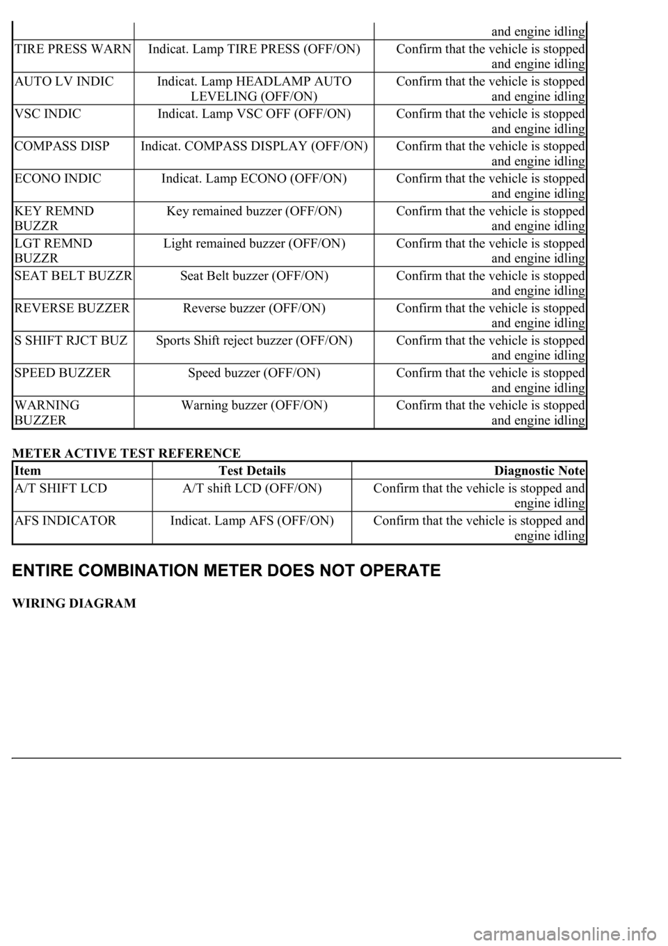
METER ACTIVE TEST REFERENCE
WIRING DIAGRAM
and engine idling
TIRE PRESS WARNIndicat. Lamp TIRE PRESS (OFF/ON)Confirm that the vehicle is stopped
and engine idling
AUTO LV INDICIndicat. Lamp HEADLAMP AUTO
LEVELING (OFF/ON)Confirm that the vehicle is stopped
and engine idling
VSC INDICIndicat. Lamp VSC OFF (OFF/ON)Confirm that the vehicle is stopped
and engine idling
COMPASS DISPIndicat. COMPASS DISPLAY (OFF/ON)Confirm that the vehicle is stopped
and engine idling
ECONO INDICIndicat. Lamp ECONO (OFF/ON)Confirm that the vehicle is stopped
and engine idling
KEY REMND
BUZZRKey remained buzzer (OFF/ON)Confirm that the vehicle is stopped
and engine idling
LGT REMND
BUZZRLight remained buzzer (OFF/ON)Confirm that the vehicle is stopped
and engine idling
SEAT BELT BUZZRSeat Belt buzzer (OFF/ON)Confirm that the vehicle is stopped
and engine idling
REVERSE BUZZERReverse buzzer (OFF/ON)Confirm that the vehicle is stopped
and engine idling
S SHIFT RJCT BUZSports Shift reject buzzer (OFF/ON)Confirm that the vehicle is stopped
and engine idling
SPEED BUZZERSpeed buzzer (OFF/ON)Confirm that the vehicle is stopped
and engine idling
WARNING
BUZZERWarning buzzer (OFF/ON)Confirm that the vehicle is stopped
and engine idling
ItemTest DetailsDiagnostic Note
A/T SHIFT LCDA/T shift LCD (OFF/ON)Confirm that the vehicle is stopped and
engine idling
AFS INDICATORIndicat. Lamp AFS (OFF/ON)Confirm that the vehicle is stopped and
engine idling
Page 1846 of 4500
Fig. 90: Identifying Fuel Sender Gauge Connector Terminals
Courtesy of TOYOTA MOTOR SALES, U.S.A., INC.
OK:
Needle position is on (FULL).
5.INSPECT FUEL LEVEL WARNING
a. Disconnect the connector from the sender gauge.
b. Turn the ignition switch to the ON position, then check that the fuel level needle indicates EMPTY
and the fuel level warning light comes on.
OK:
Fuel level warning light comes on.
Page 1847 of 4500
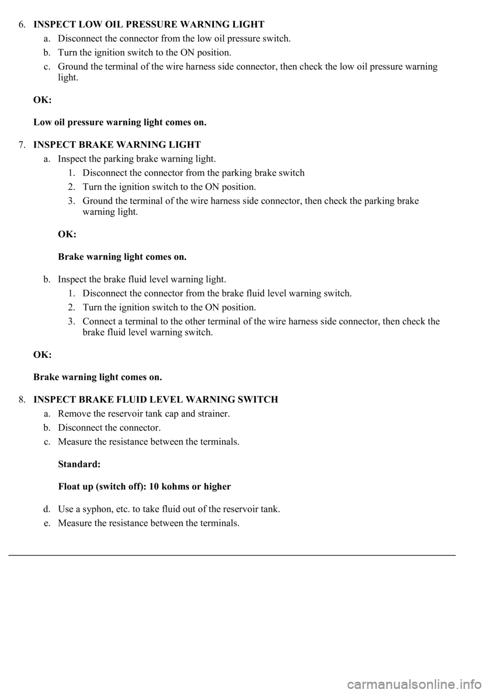
6.INSPECT LOW OIL PRESSURE WARNING LIGHT
a. Disconnect the connector from the low oil pressure switch.
b. Turn the ignition switch to the ON position.
c. Ground the terminal of the wire harness side connector, then check the low oil pressure warning
light.
OK:
Low oil pressure warning light comes on.
7.INSPECT BRAKE WARNING LIGHT
a. Inspect the parking brake warning light.
1. Disconnect the connector from the parking brake switch
2. Turn the ignition switch to the ON position.
3. Ground the terminal of the wire harness side connector, then check the parking brake
warning light.
OK:
Brake warning light comes on.
b. Inspect the brake fluid level warning light.
1. Disconnect the connector from the brake fluid level warning switch.
2. Turn the ignition switch to the ON position.
3. Connect a terminal to the other terminal of the wire harness side connector, then check the
brake fluid level warning switch.
OK:
Brake warning light comes on.
8.INSPECT BRAKE FLUID LEVEL WARNING SWITCH
a. Remove the reservoir tank cap and strainer.
b. Disconnect the connector.
c. Measure the resistance between the terminals.
Standard:
Float up (switch off): 10 kohms or higher
d. Use a syphon, etc. to take fluid out of the reservoir tank.
e. Measure the resistance between the terminals.
Page 1848 of 4500
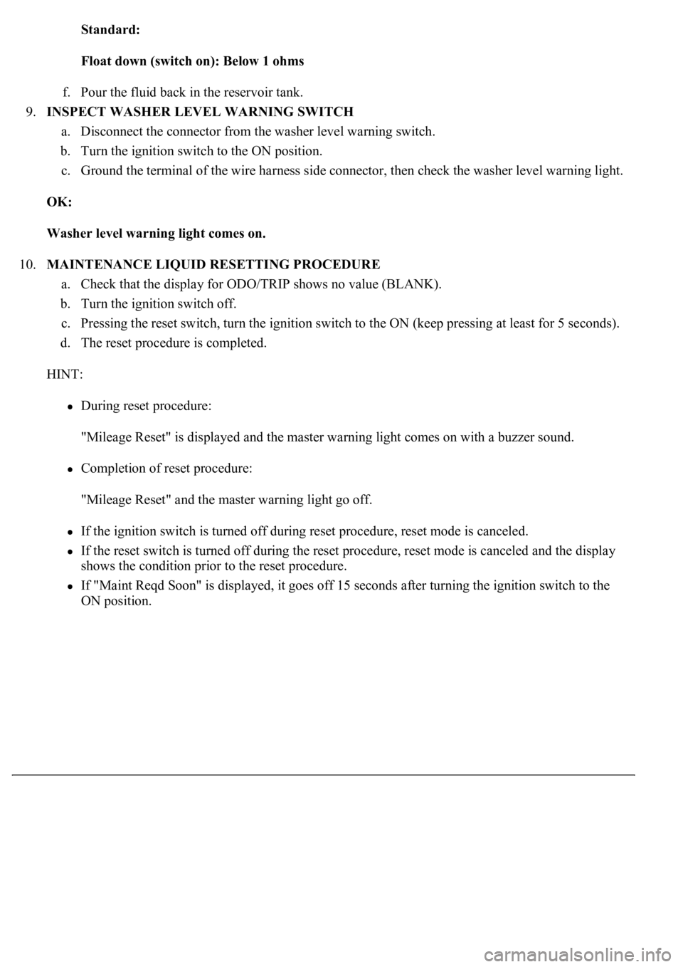
Standard:
Float down (switch on): Below 1 ohms
f. Pour the fluid back in the reservoir tank.
9.INSPECT WASHER LEVEL WARNING SWITCH
a. Disconnect the connector from the washer level warning switch.
b. Turn the ignition switch to the ON position.
c. Ground the terminal of the wire harness side connector, then check the washer level warning light.
OK:
Washer level warning light comes on.
10.MAINTENANCE LIQUID RESETTING PROCEDURE
a. Check that the display for ODO/TRIP shows no value (BLANK).
b. Turn the ignition switch off.
c. Pressing the reset switch, turn the ignition switch to the ON (keep pressing at least for 5 seconds).
d. The reset procedure is completed.
HINT:
During reset procedure:
"Mileage Reset" is displayed and the master warning light comes on with a buzzer sound.
Completion of reset procedure:
"Mileage Reset" and the master warning light go off.
If the ignition switch is turned off during reset procedure, reset mode is canceled.
If the reset switch is turned off during the reset procedure, reset mode is canceled and the display
shows the condition prior to the reset procedure.
If "Maint Reqd Soon" is displayed, it goes off 15 seconds after turning the ignition switch to the
ON position.
Page 1941 of 4500
OK: When cruise control main switch operation is performed the standard values will be above.
NG: REPLACE ECM (SEE REPLACEMENT
)
OK: PROCEED TO NEXT CIRCUIT INSPECTION SHOWN ON PROBLEM SYMPTOMS
TABLE
CIRCUIT DESCRIPTION
Making a short circuit between terminals TC and CG of the DLC3 will output DTCs from the DLC3.
WIRING DIAGRAM
Fig. 32: [Wiring Diagram
- Diagnosis Circuit]
Courtesy of TOYOTA MOTOR SALES, U.S.A., INC.
HINT:
When a particular warning light stays blinking, a ground short in the wiring of terminal TC of the DLC3 or an
internal ground short in the relevant ECU is suspected.
INSPECTION PROCEDURE
CCS
INDICATORSCruise indicator signal (Sub
CPU) /ON or OFFON: "CCS READY" ON OFF:
"CCS READY" OFF-
Page 1988 of 4500
Fig. 44: Removing Cruise Control Main Switch Assy
Courtesy of TOYOTA MOTOR SALES, U.S.A., INC.
7.INSPECT STEERING WHEEL CENTER POINT
8.INSTALL STEERING WHEEL ASSY (See step 96 in OVERHAUL
)
9.INSTALL HORN BUTTON ASSY (See step 6 in REPLACEMENT
)
10.CONNECT BATTERY NEGATIVE TERMINAL
11.INSPECT HORN BUTTON ASSY
12.INSPECT SRS WARNING LIGHT
Page 2416 of 4500
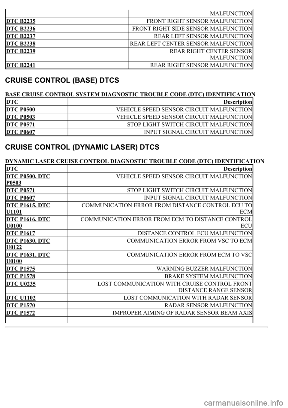
BASE CRUISE CONTROL SYSTEM DIAGNOSTIC TROUBLE CODE (DTC) IDENTIFICATION
DYNAMIC LASER CRUISE CONTROL DIAGNOSTIC TROUBLE CODE (DTC) IDENTIFICATION
MALFUNCTION
DTC B2235 FRONT RIGHT SENSOR MALFUNCTION
DTC B2236 FRONT RIGHT SIDE SENSOR MALFUNCTION
DTC B2237 REAR LEFT SENSOR MALFUNCTION
DTC B2238 REAR LEFT CENTER SENSOR MALFUNCTION
DTC B2239 REAR RIGHT CENTER SENSOR
MALFUNCTION
DTC B2241 REAR RIGHT SENSOR MALFUNCTION
DTCDescription
DTC P0500 VEHICLE SPEED SENSOR CIRCUIT MALFUNCTION
DTC P0503 VEHICLE SPEED SENSOR CIRCUIT MALFUNCTION
DTC P0571 STOP LIGHT SWITCH CIRCUIT MALFUNCTION
DTC P0607 INPUT SIGNAL CIRCUIT MALFUNCTION
DTCDescription
DTC P0500, DTC
P0503
VEHICLE SPEED SENSOR CIRCUIT MALFUNCTION
DTC P0571 STOP LIGHT SWITCH CIRCUIT MALFUNCTION
DTC P0607 INPUT SIGNAL CIRCUIT MALFUNCTION
DTC P1615, DTC
U1101
COMMUNICATION ERROR FROM DISTANCE CONTROL ECU TO
ECM
DTC P1616, DTC
U0100
COMMUNICATION ERROR FROM ECM TO DISTANCE CONTROL
ECU
DTC P1617 DISTANCE CONTROL ECU MALFUNCTION
DTC P1630, DTC
U0122
COMMUNICATION ERROR FROM VSC TO ECM
DTC P1631, DTC
U0100
COMMUNICATION ERROR FROM ECM TO VSC
DTC P1575 WARNING BUZZER MALFUNCTION
DTC P1578 BRAKE SYSTEM MALFUNCTION
DTC U0235 LOST COMMUNICATION WITH CRUISE CONTROL FRONT
DISTANCE RANGE SENSOR
DTC U1102 LOST COMMUNICATION WITH RADAR SENSOR
DTC P1570 RADAR SENSOR MALFUNCTION
DTC P1572 IMPROPER AIMING OF RADAR SENSOR BEAM AXIS
Page 2417 of 4500
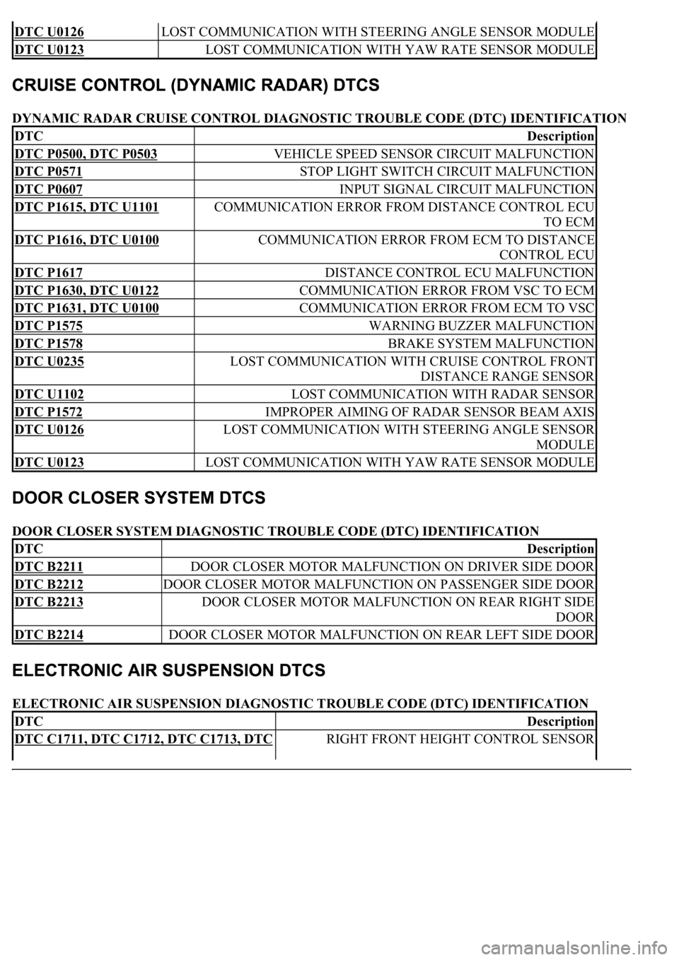
DYNAMIC RADAR CRUISE CONTROL DIAGNOSTIC TROUBLE CODE (DTC) IDENTIFICATION
DOOR CLOSER SYSTEM DIAGNOSTIC TROUBLE CODE (DTC) IDENTIFICATION
ELECTRONIC AIR SUSPENSION DIAGNOSTIC TROUBLE CODE (DTC) IDENTIFICATION
DTC U0126 LOST COMMUNICATION WITH STEERING ANGLE SENSOR MODULE
DTC U0123 LOST COMMUNICATION WITH YAW RATE SENSOR MODULE
DTCDescription
DTC P0500, DTC P0503 VEHICLE SPEED SENSOR CIRCUIT MALFUNCTION
DTC P0571 STOP LIGHT SWITCH CIRCUIT MALFUNCTION
DTC P0607 INPUT SIGNAL CIRCUIT MALFUNCTION
DTC P1615, DTC U1101 COMMUNICATION ERROR FROM DISTANCE CONTROL ECU
TO ECM
DTC P1616, DTC U0100 COMMUNICATION ERROR FROM ECM TO DISTANCE
CONTROL ECU
DTC P1617 DISTANCE CONTROL ECU MALFUNCTION
DTC P1630, DTC U0122 COMMUNICATION ERROR FROM VSC TO ECM
DTC P1631, DTC U0100 COMMUNICATION ERROR FROM ECM TO VSC
DTC P1575 WARNING BUZZER MALFUNCTION
DTC P1578 BRAKE SYSTEM MALFUNCTION
DTC U0235 LOST COMMUNICATION WITH CRUISE CONTROL FRONT
DISTANCE RANGE SENSOR
DTC U1102 LOST COMMUNICATION WITH RADAR SENSOR
DTC P1572 IMPROPER AIMING OF RADAR SENSOR BEAM AXIS
DTC U0126 LOST COMMUNICATION WITH STEERING ANGLE SENSOR
MODULE
DTC U0123 LOST COMMUNICATION WITH YAW RATE SENSOR MODULE
DTCDescription
DTC B2211 DOOR CLOSER MOTOR MALFUNCTION ON DRIVER SIDE DOOR
DTC B2212 DOOR CLOSER MOTOR MALFUNCTION ON PASSENGER SIDE DOOR
DTC B2213 DOOR CLOSER MOTOR MALFUNCTION ON REAR RIGHT SIDE
DOOR
DTC B2214 DOOR CLOSER MOTOR MALFUNCTION ON REAR LEFT SIDE DOOR
DTCDescription
DTC C1711, DTC C1712, DTC C1713, DTC RIGHT FRONT HEIGHT CONTROL SENSOR