Page 239 of 1767
Purpose
The Anti-lock Brake System (ABS) with an integrated Electronic Brake force Distribution (EBD) system con-
sists of electronic and hydraulic components. It allows you to control the braking force so that wheel lock can
be avoided during braking.
The advantages of ABS with EBD
1) Better tracking performance through improved steering wheel control.
2) Improved maneuverability and safer vehicle control.
3) Improved vehicle stability by preventing flat spins.
4) Shorter stopping distance and optimal utilisation of the rear brakes under many different circumstances.
Operation
IABS with EBD has self-test capabilities. The ABS warning lamp is illuminated for 1 second each time the
ignition switch is turned ªONº. After the engine is started, the ABS warning lamp turns off. An ABS self-test
is performed the first time the vehicle reaches 6 km/h (4 MPH) to ensure the system is operational. A
mechanical noise may be heard as the ABS performs this self-test and is a normal part of the self-test
feature. If a malfunction is detected during this check, the ABS warning lamp will stay on.
During the self-test, it also performs a EBD check when it detects a failure the ABS warning light will go
on simultaneously with the brake warning light and an audible sound will sound constantly.
IEBD system will only operate when the ABS is not in active status and it uses the inlet valves of ABS con-
trol unit to limit the pressure to the rear wheels when they tend to go into slip.
IWhen the vehicle speed is less than 10 km/h (6 MPH) the ABS system does not operate.
IWhile driving, a mechanical noise may be heard during ABS operation, this is a normal system condition.
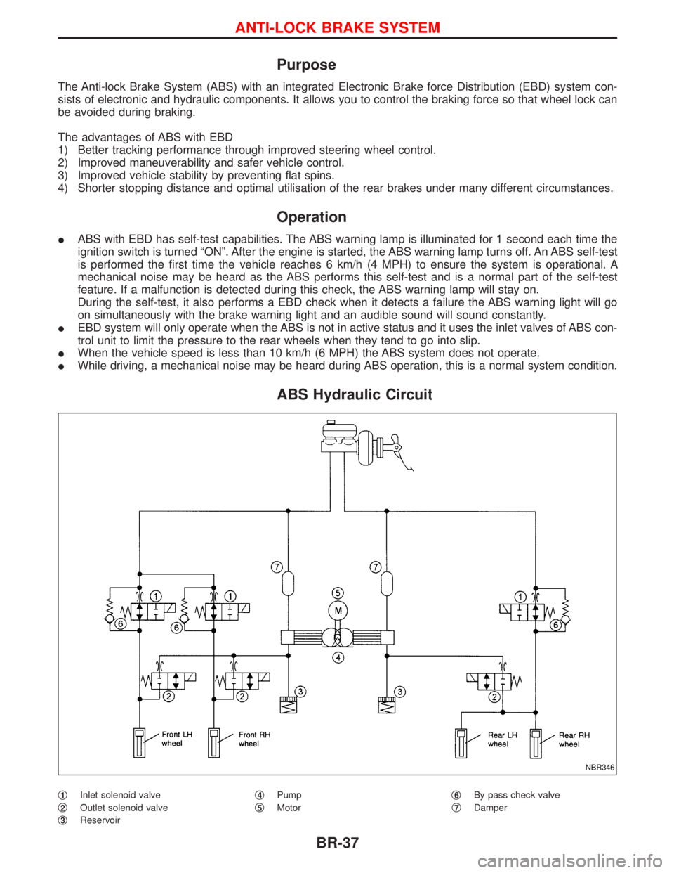
ABS Hydraulic Circuit
q1Inlet solenoid valve
q
2Outlet solenoid valve
q
3Reservoirq
4Pump
q
5Motorq
6By pass check valve
q
7Damper
NBR346
ANTI-LOCK BRAKE SYSTEM
BR-37
Page 261 of 1767
CONSULT-II Inspection Procedure
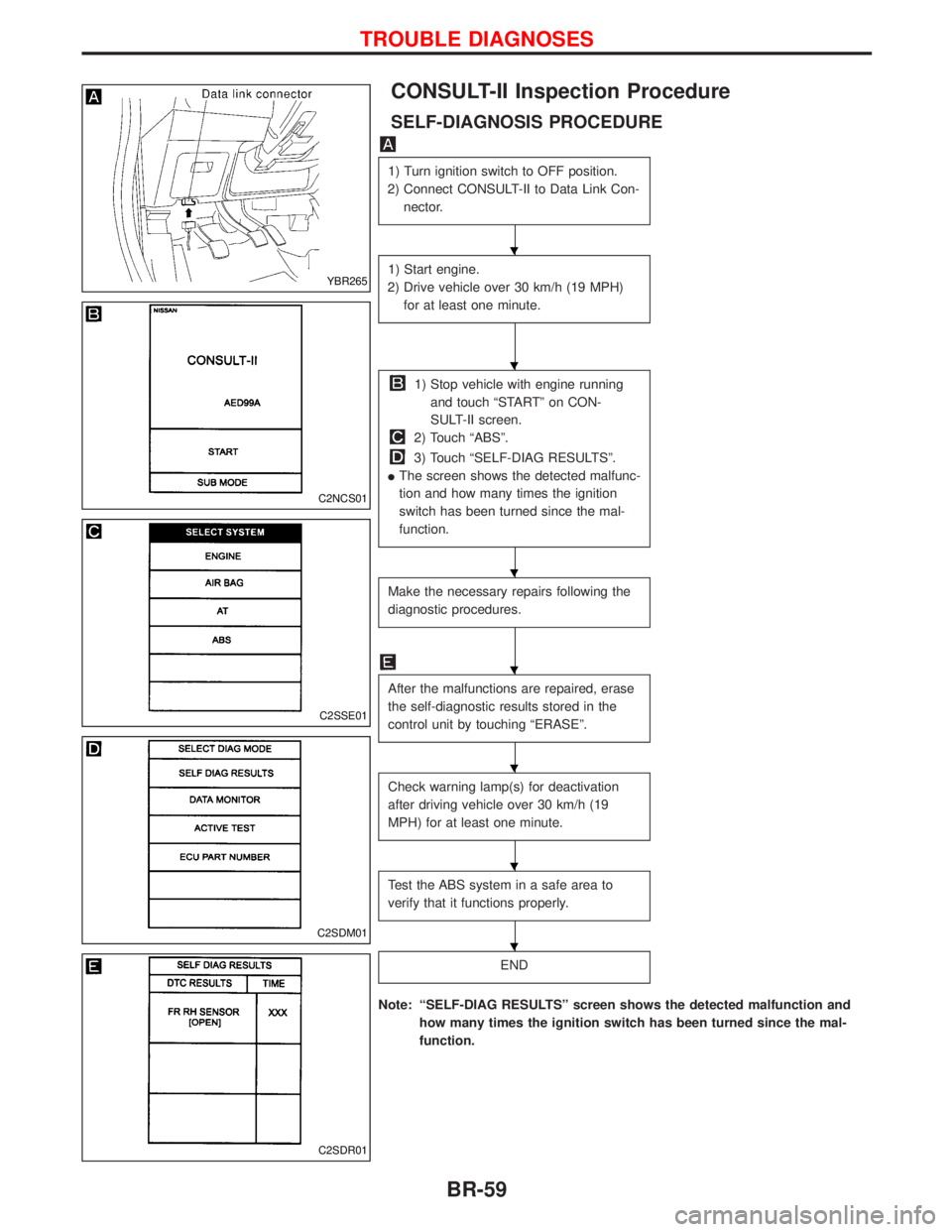
SELF-DIAGNOSIS PROCEDURE
1) Turn ignition switch to OFF position.
2) Connect CONSULT-II to Data Link Con-
nector.
1) Start engine.
2) Drive vehicle over 30 km/h (19 MPH)
for at least one minute.
1) Stop vehicle with engine running
and touch ªSTARTº on CON-
SULT-II screen.
2) Touch ªABSº.
3) Touch ªSELF-DIAG RESULTSº.
IThe screen shows the detected malfunc-
tion and how many times the ignition
switch has been turned since the mal-
function.
Make the necessary repairs following the
diagnostic procedures.
After the malfunctions are repaired, erase
the self-diagnostic results stored in the
control unit by touching ªERASEº.
Check warning lamp(s) for deactivation
after driving vehicle over 30 km/h (19
MPH) for at least one minute.
Test the ABS system in a safe area to
verify that it functions properly.
END
Note: ªSELF-DIAG RESULTSº screen shows the detected malfunction and
how many times the ignition switch has been turned since the mal-
function.
YBR265
C2NCS01
C2SSE01
C2SDM01
C2SDR01
H
H
H
H
H
H
H
TROUBLE DIAGNOSES
BR-59
Page 266 of 1767
ACTIVE TEST MODE
TEST ITEM CONDITION JUDGEMENT
FR RH SOLENOID
FR LH SOLENOID
RR SOLENOID
Engine is running.Brake fluid pressure control operation
IN SOL OUT SOL
UP (Increase):
KEEP (Hold):
DOWN (Decrease):OFF
ON
ONOFF
OFF
ON
ABS MOTORABS actuator motor
ON: Motor runs (ABS motor relay ON)
OFF: Motor stops (ABS motor relay OFF)
G-SWITCHIgnition switch is ON or
engine is running.Check G-switch circuit
OFF: G-switch OFF
ON: G-switch ON
Note: Active test will automatically stop ten seconds after the test starts. (LIMIT SIGNAL monitor shows
ON.)
TROUBLE DIAGNOSES
CONSULT-II Inspection Procedure (Cont'd)
BR-64
Page 282 of 1767

Diagnostic Procedure 10 (Pedal vibration and
noise)
INSPECTION START
1. Apply brake.
2. Start engine.
3. Does the symptom appear only when
engine is started?
No
EYe s
Carry out self-diagnosis.
Refer to BR-59.
CHECK IF SYMPTOM APPEARS.
Does the symptom appear when electrical
equipment switches (such as headlamp)
are operated?
Ye s
ENo
Go toin Diagnostic
Procedure 12, BR-81.
CHECK WHEEL SENSOR.
Check wheel sensor shield ground. For
location of shield ground, refer to wiring
diagram and ªHARNESS LAYOUTº in EL
section.
OK
ENG
Repair wheel sensor.
CHECK HARNESS CONNECTOR.
Check ABS actuator and electric unit pin
terminals for damage or the connection of
ABS actuator and electric unit harness
connector.
Reconnect ABS actuator and electric unit
harness connector. Then retest.
Note: ABS may operate and cause vibration under any of the
following conditions.
Diagnostic Procedure 11 (Long stopping
distance)
CHECK ABS PERFORMANCE
Disconnect ABS actuator and electric unit
connector and check whether stopping
distance is still long.
Ye s
ENo
Go toin Diagnostic
Procedure 12, BR-81.
Perform Preliminary Check and air bleed-
ing.
Note: Stopping distance may be larger than vehicles without
ABS when road condition is slippery.
SAT797AH
H
H
H
TROUBLE DIAGNOSES
BR-80
Page 402 of 1767
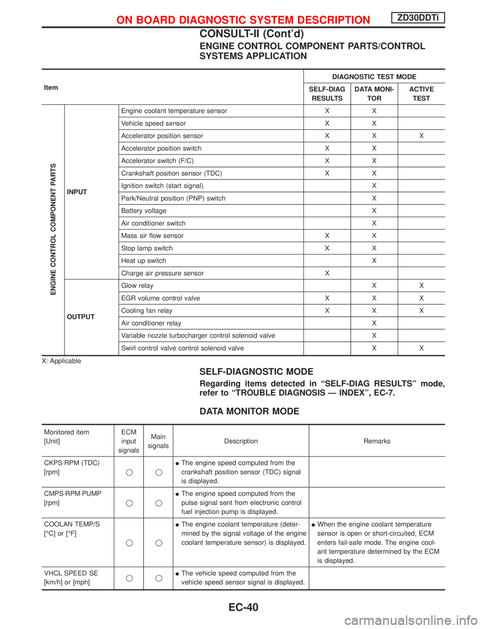
ENGINE CONTROL COMPONENT PARTS/CONTROL
SYSTEMS APPLICATION
ItemDIAGNOSTIC TEST MODE
SELF-DIAG
RESULTSDATA MONI-
TORACTIVE
TEST
ENGINE CONTROL COMPONENT PARTS
INPUTEngine coolant temperature sensor X X
Vehicle speed sensor X X
Accelerator position sensor X X X
Accelerator position switch X X
Accelerator switch (F/C) X X
Crankshaft position sensor (TDC) X X
Ignition switch (start signal) X
Park/Neutral position (PNP) switch X
Battery voltage X
Air conditioner switch X
Mass air flow sensor X X
Stop lamp switch X X
Heat up switch X
Charge air pressure sensor X
OUTPUTGlow relayXX
EGR volume control valve X X X
Cooling fan relay X X X
Air conditioner relay X
Variable nozzle turbocharger control solenoid valve X
Swirl control valve control solenoid valve X X
X: Applicable
SELF-DIAGNOSTIC MODE
Regarding items detected in ªSELF-DIAG RESULTSº mode,
refer to ªTROUBLE DIAGNOSIS Ð INDEXº, EC-7.
DATA MONITOR MODE
Monitored item
[Unit]ECM
input
signalsMain
signalsDescription Remarks
CKPS×RPM (TDC)
[rpm]qqIThe engine speed computed from the
crankshaft position sensor (TDC) signal
is displayed.
CMPS×RPM×PUMP
[rpm]qqIThe engine speed computed from the
pulse signal sent from electronic control
fuel injection pump is displayed.
COOLAN TEMP/S
[ÉC] or [ÉF]
qqIThe engine coolant temperature (deter-
mined by the signal voltage of the engine
coolant temperature sensor) is displayed.IWhen the engine coolant temperature
sensor is open or short-circuited, ECM
enters fail-safe mode. The engine cool-
ant temperature determined by the ECM
is displayed.
VHCL SPEED SE
[km/h] or [mph]qqIThe vehicle speed computed from the
vehicle speed sensor signal is displayed.
ON BOARD DIAGNOSTIC SYSTEM DESCRIPTIONZD30DDTi
CONSULT-II (Cont'd)
EC-40
Page 403 of 1767
![NISSAN TERRANO 2002 Service Repair Manual Monitored item
[Unit]ECM
input
signalsMain
signalsDescription Remarks
FUEL TEMP SEN
[ÉC] or [ÉF]qqIThe fuel temperature (sent from elec-
tronic control fuel injection pump) is dis-
played.
ACCEL POS NISSAN TERRANO 2002 Service Repair Manual Monitored item
[Unit]ECM
input
signalsMain
signalsDescription Remarks
FUEL TEMP SEN
[ÉC] or [ÉF]qqIThe fuel temperature (sent from elec-
tronic control fuel injection pump) is dis-
played.
ACCEL POS](/manual-img/5/57393/w960_57393-402.png)
Monitored item
[Unit]ECM
input
signalsMain
signalsDescription Remarks
FUEL TEMP SEN
[ÉC] or [ÉF]qqIThe fuel temperature (sent from elec-
tronic control fuel injection pump) is dis-
played.
ACCEL POS SEN [V]
qqIThe accelerator position sensor signal
voltage is displayed.
FULL ACCEL SW
[ON/OFF]qqIIndicates [ON/OFF] condition from the
accelerator position switch signal.
ACCEL SW (FC)
[OPEN/CLOSE]qqIIndicates [OPEN/CLOSE] condition from
the accelerator switch (FC) signal.
OFF ACCEL SW
[ON/OFF]qqIIndicates [ON/OFF] condition from the
accelerator position switch signal.
SPILL/V [ÉCA]
qIThe control position of spill valve (sent
from electronic control fuel injection
pump) is displayed.
BATTERY VOLT [V]
qqIThe power supply voltage of ECM is dis-
played.
P/N POSI SW
[ON/OFF]qqIIndicates [ON/OFF] condition from the
park/neutral position switch signal.
START SIGNAL
[ON/OFF]qqIIndicates [ON/OFF] condition from the
starter signal.IAfter starting the engine, [OFF] is dis-
played regardless of the starter signal.
AIR COND SIG
[ON/OFF]qqIIndicates [ON/OFF] condition of the air
conditioner switch as determined by the
air conditioner signal.
BRAKE SW [ON/OFF]
qqIIndicates [ON/OFF] condition from the
stop lamp switch signal.
IGN SW
[ON/OFF]qqIIndicates [ON/OFF] condition from igni-
tion switch signal.
WARM UP SW
[ON/OFF]qIIndicates [ON/OFF] condition from the
heat up switch signal.
MAS AIR/FL SE [V]
qqIThe signal voltage of the mass air flow
sensor is displayed.IWhen the engine is stopped, a certain
value is indicated.
DECELER F/CUT
[ON/OFF]qIThe [ON/OFF] condition from decelera-
tion fuel cut signal (sent from electronic
control fuel injection pump) is displayed.
INJ TIMG C/V [%]
qIThe duty ratio of fuel injection timing
control valve (sent from electronic control
fuel injection pump) is displayed.
AIR COND RLY
[ON/OFF]qIIndicates the control condition of the air
conditioner relay (determined by ECM
according to the input signals).
GLOW RLY [ON/OFF]
qIThe glow relay control condition (deter-
mined by ECM according to the input
signal) is displayed.
COOLING FAN
[ON/OFF]
qIIndicates the control condition of the
cooling fans (determined by ECM
according to the input signal).
ION ... Operates.
OFF ... Stopped.
ON BOARD DIAGNOSTIC SYSTEM DESCRIPTIONZD30DDTi
CONSULT-II (Cont'd)
EC-41
Page 424 of 1767
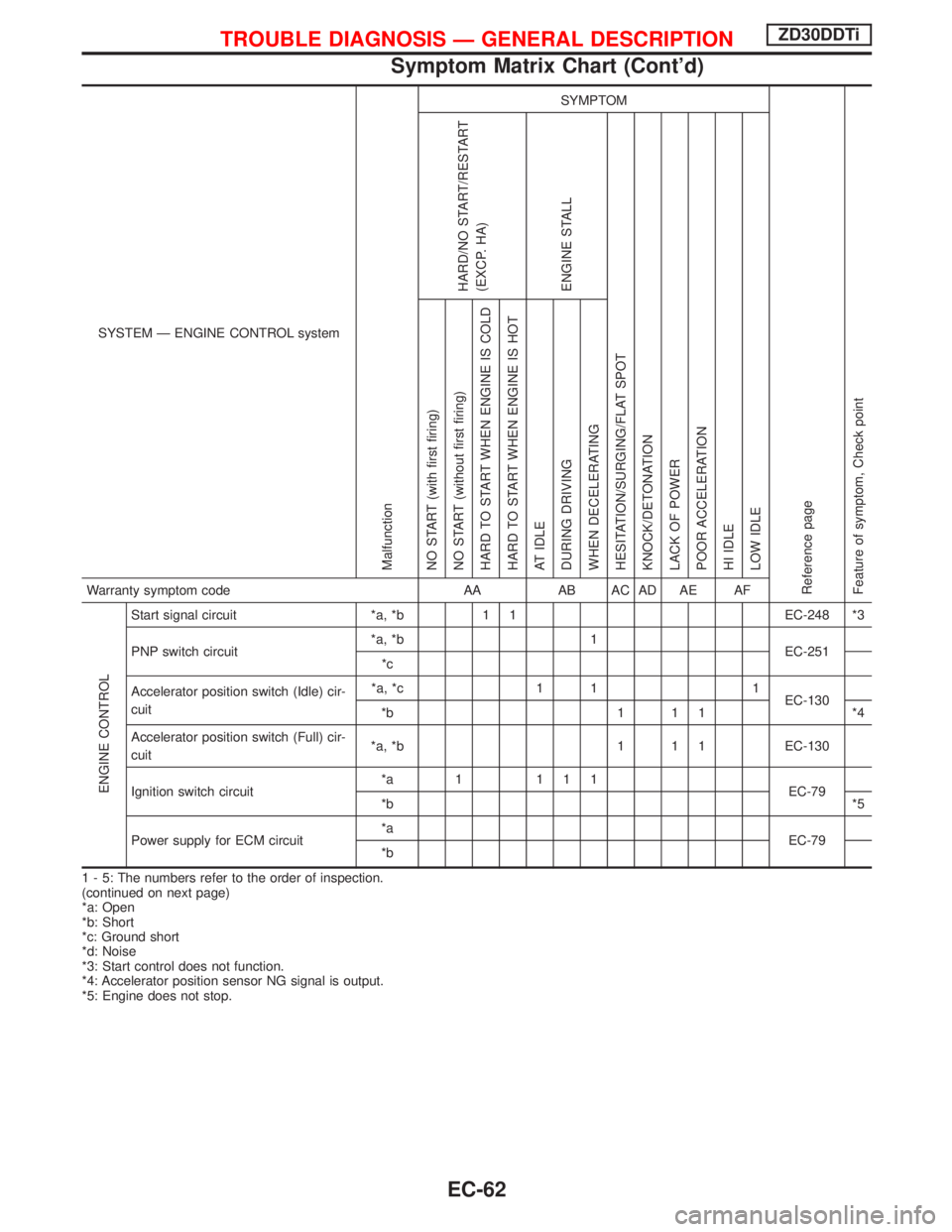
SYSTEM Ð ENGINE CONTROL system
Malfunction
SYMPTOM
Reference page
Feature of symptom, Check pointHARD/NO START/RESTART
(EXCP. HA)
ENGINE STALL
HESITATION/SURGING/FLAT SPOT
KNOCK/DETONATION
LACK OF POWER
POOR ACCELERATION
HI IDLE
LOW IDLE NO START (with first firing)
NO START (without first firing)
HARD TO START WHEN ENGINE IS COLD
HARD TO START WHEN ENGINE IS HOT
AT IDLE
DURING DRIVING
WHEN DECELERATINGWarranty symptom code AA AB AC AD AE AF
ENGINE CONTROL
Start signal circuit *a, *b 1 1 EC-248 *3
PNP switch circuit*a, *b 1
EC-251
*c
Accelerator position switch (Idle) cir-
cuit*a, *c 1 1 1
EC-130
*b 1 1 1 *4
Accelerator position switch (Full) cir-
cuit*a, *b 1 1 1 EC-130
Ignition switch circuit*a 1 111
EC-79
*b*5
Power supply for ECM circuit*a
EC-79
*b
1 - 5: The numbers refer to the order of inspection.
(continued on next page)
*a: Open
*b: Short
*c: Ground short
*d: Noise
*3: Start control does not function.
*4: Accelerator position sensor NG signal is output.
*5: Engine does not stop.
TROUBLE DIAGNOSIS Ð GENERAL DESCRIPTIONZD30DDTi
Symptom Matrix Chart (Cont'd)
EC-62
Page 425 of 1767
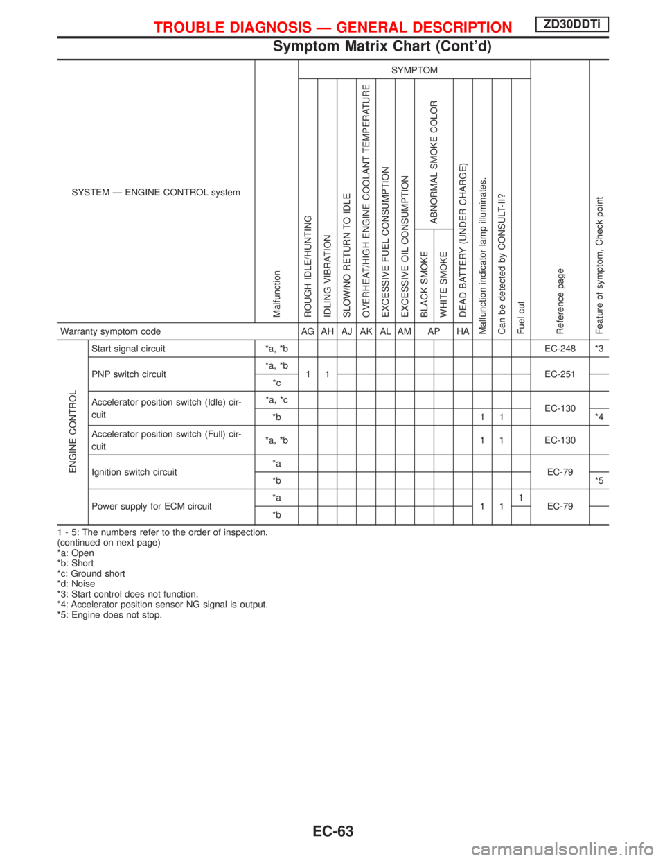
SYSTEM Ð ENGINE CONTROL system
Malfunction
SYMPTOM
Reference page
Feature of symptom, Check pointROUGH IDLE/HUNTING
IDLING VIBRATION
SLOW/NO RETURN TO IDLE
OVERHEAT/HIGH ENGINE COOLANT TEMPERATURE
EXCESSIVE FUEL CONSUMPTION
EXCESSIVE OIL CONSUMPTION
ABNORMAL SMOKE COLOR
DEAD BATTERY (UNDER CHARGE)
Malfunction indicator lamp illuminates.
Can be detected by CONSULT-II?
Fuel cutBLACK SMOKE
WHITE SMOKEWarranty symptom code AG AH AJ AK AL AM AP HA
ENGINE CONTROL
Start signal circuit *a, *b EC-248 *3
PNP switch circuit*a, *b
1 1 EC-251
*c
Accelerator position switch (Idle) cir-
cuit*a, *c
EC-130
*b 1 1 *4
Accelerator position switch (Full) cir-
cuit*a, *b 1 1 EC-130
Ignition switch circuit*a
EC-79
*b*5
Power supply for ECM circuit*a
111
EC-79
*b
1 - 5: The numbers refer to the order of inspection.
(continued on next page)
*a: Open
*b: Short
*c: Ground short
*d: Noise
*3: Start control does not function.
*4: Accelerator position sensor NG signal is output.
*5: Engine does not stop.
TROUBLE DIAGNOSIS Ð GENERAL DESCRIPTIONZD30DDTi
Symptom Matrix Chart (Cont'd)
EC-63