2002 NISSAN TERRANO stop start
[x] Cancel search: stop startPage 1359 of 1767
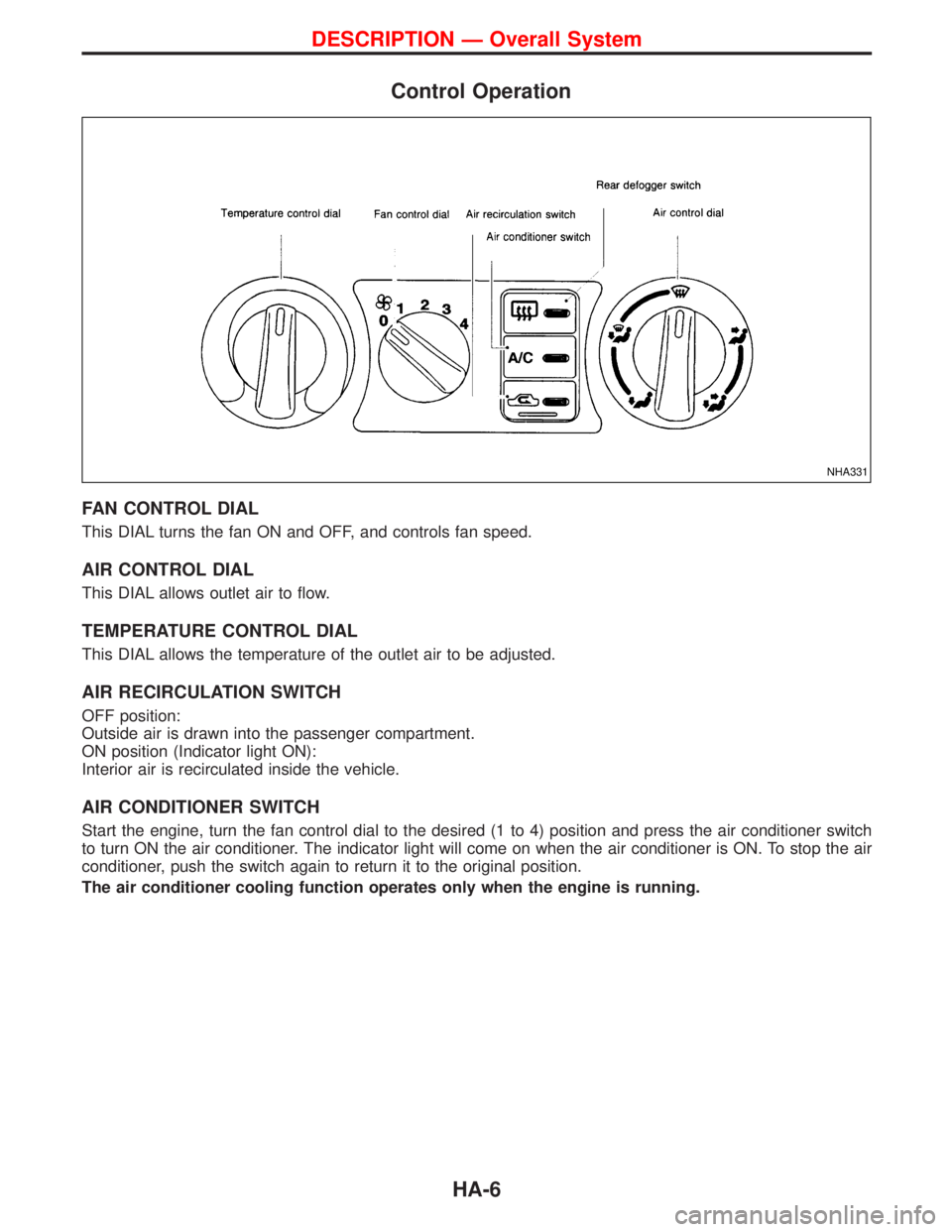
Control Operation
FAN CONTROL DIAL
This DIAL turns the fan ON and OFF, and controls fan speed.
AIR CONTROL DIAL
This DIAL allows outlet air to flow.
TEMPERATURE CONTROL DIAL
This DIAL allows the temperature of the outlet air to be adjusted.
AIR RECIRCULATION SWITCH
OFF position:
Outside air is drawn into the passenger compartment.
ON position (Indicator light ON):
Interior air is recirculated inside the vehicle.
AIR CONDITIONER SWITCH
Start the engine, turn the fan control dial to the desired (1 to 4) position and press the air conditioner switch
to turn ON the air conditioner. The indicator light will come on when the air conditioner is ON. To stop the air
conditioner, push the switch again to return it to the original position.
The air conditioner cooling function operates only when the engine is running.
NHA331
DESCRIPTION Ð Overall System
HA-6
Page 1375 of 1767
Lubrication Oil
Name: Nissan A/C System Oil Type R
Part number: KLH00-PAGR0
Maintenance of Oil Quantity in Compressor
The oil used to lubricate the compressor circulates through the
system with the refrigerant. Whenever any component of the sys-
tem is replaced or a large amount of gas leakage occurs, add oil
to the compressor to maintain the specified amount.
If oil quantity is not maintained properly, the following malfunctions
may result:
ILack of oil: May lead to a seized compressor
IExcessive oil: Inadequate cooling (thermal exchange impeded)
Checking and Adjusting
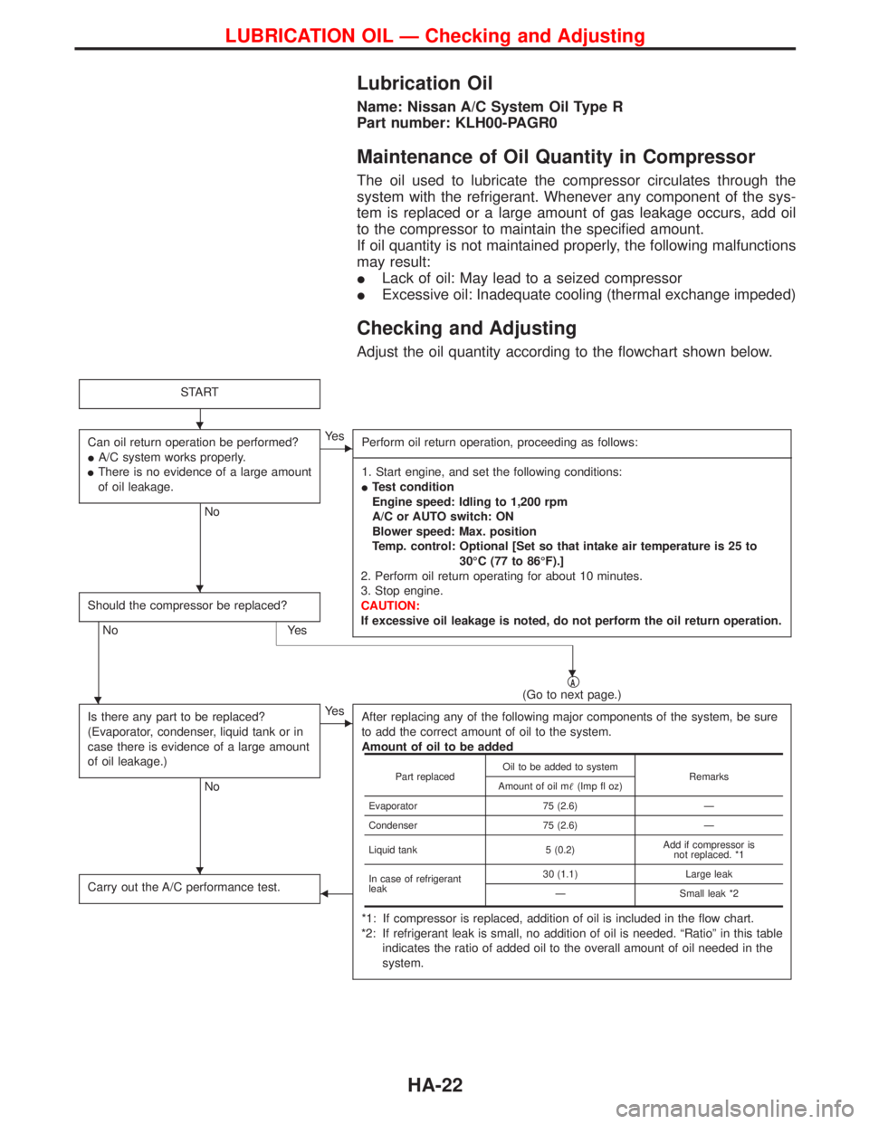
Adjust the oil quantity according to the flowchart shown below.
START
Can oil return operation be performed?
IA/C system works properly.
IThere is no evidence of a large amount
of oil leakage.
No
EYe s
Perform oil return operation, proceeding as follows:
-------------------------------------------------------------------------------------------------------------------------------------------------------------------------------------------------------------------------------------------------------------------------------------------------------------------------------------------------------------------------------------------------------------------------------------------------------------------------------------------------------------------------------------------------------------
1. Start engine, and set the following conditions:
ITest condition
Engine speed: Idling to 1,200 rpm
A/C or AUTO switch: ON
Blower speed: Max. position
Temp. control: Optional [Set so that intake air temperature is 25 to
30ÉC (77 to 86ÉF).]
2. Perform oil return operating for about 10 minutes.
3. Stop engine.
CAUTION:
If excessive oil leakage is noted, do not perform the oil return operation.
Should the compressor be replaced?
No Yes
qA(Go to next page.)
Is there any part to be replaced?
(Evaporator, condenser, liquid tank or in
case there is evidence of a large amount
of oil leakage.)
No
EYe s
After replacing any of the following major components of the system, be sure
to add the correct amount of oil to the system.
Amount of oil to be added
*1: If compressor is replaced, addition of oil is included in the flow chart.
*2: If refrigerant leak is small, no addition of oil is needed. ªRatioº in this table
indicates the ratio of added oil to the overall amount of oil needed in the
system.
Carry out the A/C performance test.F
Part replacedOil to be added to system
Remarks
Amount of oil m(Imp fl oz)
Evaporator 75 (2.6) Ð
Condenser 75 (2.6) Ð
Liquid tank 5 (0.2)Add if compressor is
not replaced. *1
In case of refrigerant
leak30 (1.1) Large leak
Ð Small leak *2
H
H
H
H
H
LUBRICATION OIL Ð Checking and Adjusting
HA-22
Page 1387 of 1767
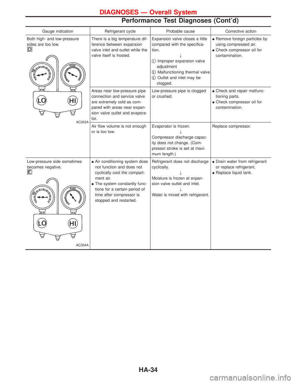
Gauge indication Refrigerant cycle Probable cause Corrective action
Both high- and low-pressure
sides are too low.
AC353A
There is a big temperature dif-
ference between expansion
valve inlet and outlet while the
valve itself is frosted.Expansion valve closes a little
compared with the specifica-
tion.
"
q
1Improper expansion valve
adjustment
q
2Malfunctioning thermal valve
q
3Outlet and inlet may be
clogged.IRemove foreign particles by
using compressed air.
ICheck compressor oil for
contamination.
Areas near low-pressure pipe
connection and service valve
are extremely cold as com-
pared with areas near expan-
sion valve outlet and evapora-
tor.Low-pressure pipe is clogged
or crushed.ICheck and repair malfunc-
tioning parts.
ICheck compressor oil for
contamination.
Air flow volume is not enough
or is too low.Evaporator is frozen.
"
Compressor discharge capac-
ity does not change. (Com-
pressor stroke is set at maxi-
mum length.)Replace compressor.
Low-pressure side sometimes
becomes negative.
AC354A
IAir conditioning system does
not function and does not
cyclically cool the compart-
ment air.
IThe system constantly func-
tions for a certain period of
time after compressor is
stopped and restarted.Refrigerant does not discharge
cyclically.
"
Moisture is frozen at expan-
sion valve outlet and inlet.
"
Water is mixed with refrigerant.IDrain water from refrigerant
or replace refrigerant.
IReplace liquid tank.
DIAGNOSES Ð Overall System
Performance Test Diagnoses (Cont'd)
HA-34
Page 1423 of 1767
Pre-delivery inspection.....................................MA-3
Priming pump .................................................EC-50
Propeller shaft ............................................PD-5, 57
Propeller shaft greasing...........................MA-36, 38
Propeller shaft inspection ........................MA-36, 38
Propeller shaft on vehicle service ....................PD-6
Pump communication line (Electronic
Fuel Injection Pump) ................................EC-175
Pump control module (Electronic Fuel
Injection Pump).........................................EC-189
R
Radiator ....................................................LC-14, 32
Rear axle................................................RA-4, 6, 12
Rear bumper .....................................................BT-8
Rear case (Transfer)...................................TF-9, 24
Rear combination lamp removal and
installation .....................................................BT-8
Rear door ........................................................BT-12
Rear door trim...........................................BT-18, 19
Rear drum brake ............................................BR-31
Rear fog lamp .................................................EL-54
Rear side window .....................................BT-21, 43
Rear suspension ........................................RA-4, 12
Rear window defogger..................EL-107, 109, 110
Refrigerant connection precaution ...................HA-4
Refrigerant general precaution.........................HA-3
Refrigerant lines .............................................HA-17
Refrigeration cycle............................................HA-9
REMOTE - Wiring diagram ...........................EL-122
Removal and installation (A/T) ......................AT-116
Removal and installation (Transfer) ..................TF-7
Reverse clutch ..............................................AT-151
Reverse idler shaft (M/T)................................MT-11
Reverse main gear (M/T) ...............................MT-11
Revolution sensor (A/T) ..........................AT-50, 114
R/FOG - Wiring diagram .................................EL-54
Ring gear diff. inspection .........................PD-20, 42
Rocker cover ..................................................EM-20
Roof trim .........................................................BT-20
Rotor disc (front) .............................................FA-18
S
Screw jack .......................................................GI-32
Seal - See Exterior .........................................BT-21
Seat belt inspection .................................MA-36, 45
Seat belt pre-tensioner.................................RS-2, 9
Seat belt pre-tensioner disposal ....................RS-20
Seat belt, front ..................................................RS-4
Seat, front .......................................................BT-34
Seat, second (2nd) .........................................BT-37
Seat, third (3rd) ...............................................BT-39
Second (2nd) seat ..........................................BT-37
Self-diagnostic results ............................EC-35, 324
Shift control (Transfer) ..............................TF-11, 24Shift control components
(M/T) ............................MT-13, 14, 15, 21, 23, 31
Shift fork (M/T) ...............................................MT-13
Shift schedule................................................AT-196
Shift solenoid valve A (A/T).............................AT-63
Shift solenoid valve B (A/T) ............................AT-66
Shock absorber (front) ....................................FA-30
Shock absorber (rear) ..............................RA-14, 16
Side air bag ....................................................RS-18
Side air bag (satellite) sensor ........................RS-13
Side bearing preload diff. ...............................PD-24
Side trim....................................................BT-18, 21
Side window - See Rear side window ............BT-21
S/LOCK - Wiring diagram .............................EL-150
SMJ (super multiple junction) .......................Foldout
Speedometer...................................................EL-72
Spill valve .....................................................EC-182
Spiral cable.....................................................RS-14
SROOF - Wiring diagram .............................EL-130
SRS - See Supplemental Restraint
System ..........................................................RS-6
SRS - Wiring diagram ....................................RS-32
SRS Trouble diagnoses .................................RS-26
S/SIG - Wiring diagram ................................EC-248
Stabilizer bar (front) ....................................FA-4, 33
Stabilizer bar (rear) ..................................RA-15, 16
Stall test (A/T) .........................................AT-27, 196
Standardized relay ............................................EL-4
START - Wiring diagram ................................SC-14
Start signal ...................................................EC-248
Starter .............................................................SC-17
Starting system...............................................SC-13
Steering gear and linkage inspection ......MA-36, 43
Steering gear oil level ..............................MA-36, 44
Steering gear, linkage and transfer
gear inspection ..............................MA-36, 43, 44
Steering linkage ........................................ST-17, 22
Steering switch................................................EL-25
Steering wheel and column ........................ST-8, 22
Steering wheel play ..........................................ST-4
Steering wheel turning force .............................ST-6
Stop lamp ........................................................EL-48
Stop lamp switch ..................................EC-204, 403
STOP/L - Wiring diagram................................EL-48
Striking rod (M/T) ...........................................MT-13
Sub-gear (M/T) ...............................................MT-11
Sun roof, electric ...........................................EL-130
Sunroof............................................................BT-40
Super lock ............................EL-145, 146, 148, 158
Supplemental Restraint System .......................RS-6
Swirl control valve control solenoid
valve .........................................................EC-263
SWL/V - Wiring diagram ..............................EC-265
Symptom matrix chart ............................EC-56, 340
T
Tachometer .....................................................EL-72
Tail lamp ..........................................................EL-45
ALPHABETICAL INDEX
IDX-6
Page 1480 of 1767
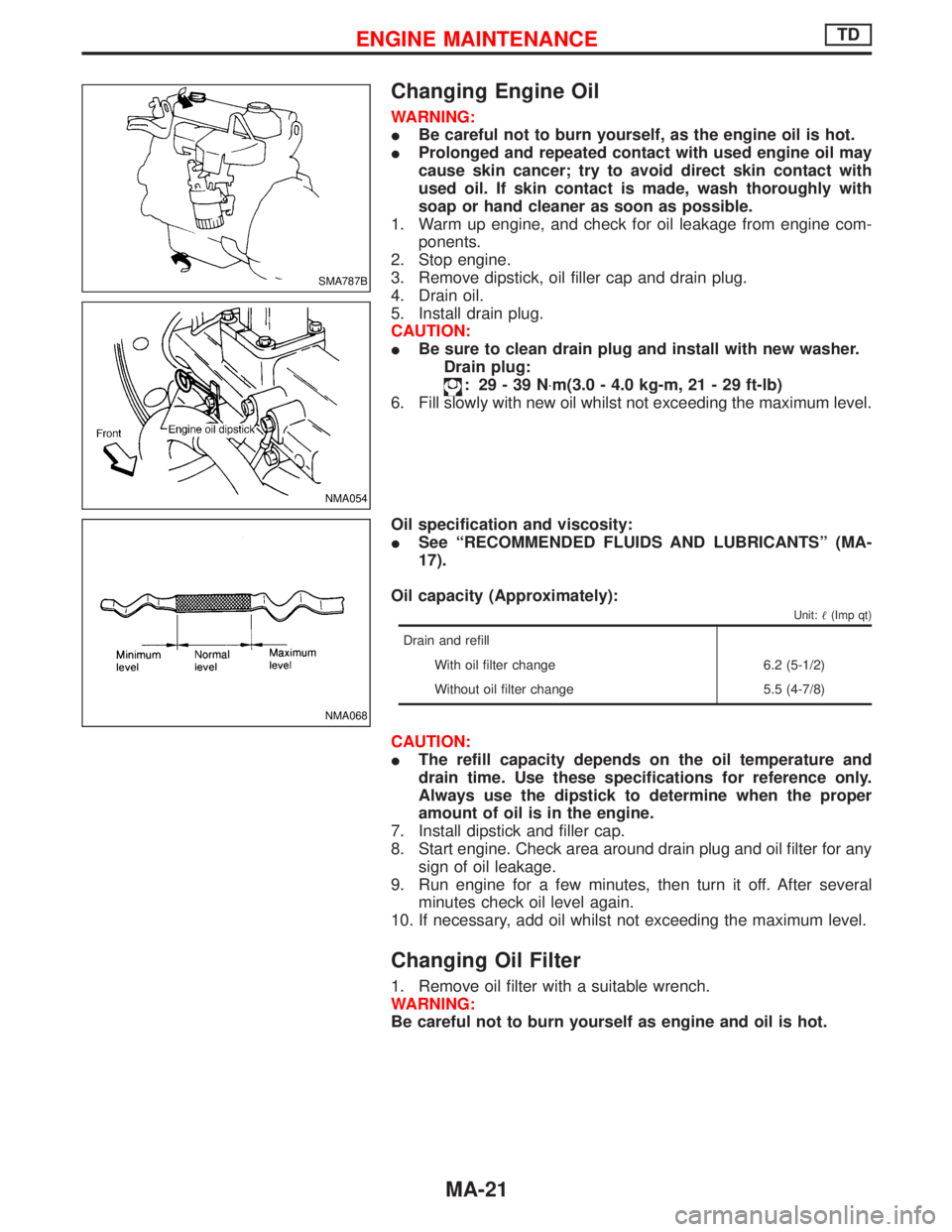
Changing Engine Oil
WARNING:
IBe careful not to burn yourself, as the engine oil is hot.
IProlonged and repeated contact with used engine oil may
cause skin cancer; try to avoid direct skin contact with
used oil. If skin contact is made, wash thoroughly with
soap or hand cleaner as soon as possible.
1. Warm up engine, and check for oil leakage from engine com-
ponents.
2. Stop engine.
3. Remove dipstick, oil filler cap and drain plug.
4. Drain oil.
5. Install drain plug.
CAUTION:
IBe sure to clean drain plug and install with new washer.
Drain plug:
: 29-39N×m(3.0 - 4.0 kg-m, 21 - 29 ft-lb)
6. Fill slowly with new oil whilst not exceeding the maximum level.
Oil specification and viscosity:
ISee ªRECOMMENDED FLUIDS AND LUBRICANTSº (MA-
17).
Oil capacity (Approximately):
Unit:(Imp qt)
Drain and refill
With oil filter change 6.2 (5-1/2)
Without oil filter change 5.5 (4-7/8)
CAUTION:
IThe refill capacity depends on the oil temperature and
drain time. Use these specifications for reference only.
Always use the dipstick to determine when the proper
amount of oil is in the engine.
7. Install dipstick and filler cap.
8. Start engine. Check area around drain plug and oil filter for any
sign of oil leakage.
9. Run engine for a few minutes, then turn it off. After several
minutes check oil level again.
10. If necessary, add oil whilst not exceeding the maximum level.
Changing Oil Filter
1. Remove oil filter with a suitable wrench.
WARNING:
Be careful not to burn yourself as engine and oil is hot.
SMA787B
NMA054
NMA068
ENGINE MAINTENANCETD
MA-21
Page 1488 of 1767
Removal
WATER PUMP, ALTERNATOR AND AIR CONDITIONER
BELT
1. Remove radiator shroud.
2. Contract and hold the auto tensioner using the following proce-
dure.
a. Securely hold the 19 mm (0.75 in) hexagonal portion A of auto
tensioner with a closed wrench.
IPreferably use a tool with a handhold of 500 mm (19.69 in) or
more in length.
INo bolts or nuts are required to be loosened during the opera-
tion.
b. Turn the hexagonal portion A in the direction shown by the
arrow to contract the damper unit of the auto tensioner.
CAUTION:
IBecause the tensioner has a high tension, it shall be
securely held and turned with a closed wrench.
IBecause the hexagonal portion A of the tensioner is made
of aluminum and may be damaged by sudden input, turn
it slowly according to the contraction of the damper unit.
3. Remove the belt from the alternator pulley first, and then
remove it from the other pulleys.
IIf the tensioner is not held firmly, your finger may get caught
between the belt and the pulleys. Confirm the holding of the
tensioner, and then hold the belt side in the place away from
the pulleys to attach or remove the belt, paying attention to
prevent your finger from being caught.
CAUTION:
IWhen handling the belt, pay attention to prevent the oil or
coolant from adhering to the belt.
IDo not distort or bend the belt intensively.
Installation
IInstall the belt in the reverse order of removal.
IAfter installation of the belt, confirm that the belt engages the
pulleys securely.
IDepending on the engagement between the belt and the idler
pulley, noise (belt noise) may be heard when the engine is
started just after installation. This noise will stop with time.
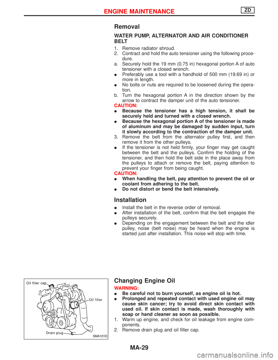
Changing Engine Oil
WARNING:
IBe careful not to burn yourself, as engine oil is hot.
IProlonged and repeated contact with used engine oil may
cause skin cancer; try to avoid direct skin contact with
used oil. If skin contact is made, wash thoroughly with
soap or hand cleaner as soon as possible.
1. Warm up engine, and check for oil leakage from engine com-
ponents.
2. Remove drain plug and oil filler cap.
SMA101D
ENGINE MAINTENANCEZD
MA-29
Page 1690 of 1767
![NISSAN TERRANO 2002 Service Repair Manual Fig. 2 INITIAL CHARGING CURRENT SETTING (Slow charge)
CON-
VERTED
SPECIFIC
GRAVITYBATTERY TYPE
28B19R(L)
34B19R(L)
46B24R(L)
55B24R(L)
50D23R(L)
55D23R(L)
025 [YUASA type code]
027 [YUASA type code]
6 NISSAN TERRANO 2002 Service Repair Manual Fig. 2 INITIAL CHARGING CURRENT SETTING (Slow charge)
CON-
VERTED
SPECIFIC
GRAVITYBATTERY TYPE
28B19R(L)
34B19R(L)
46B24R(L)
55B24R(L)
50D23R(L)
55D23R(L)
025 [YUASA type code]
027 [YUASA type code]
6](/manual-img/5/57393/w960_57393-1689.png)
Fig. 2 INITIAL CHARGING CURRENT SETTING (Slow charge)
CON-
VERTED
SPECIFIC
GRAVITYBATTERY TYPE
28B19R(L)
34B19R(L)
46B24R(L)
55B24R(L)
50D23R(L)
55D23R(L)
025 [YUASA type code]
027 [YUASA type code]
65D26R(L)
80D26R(L)
L2-580 R/L (65 Ah)
063 [YUASA type code]
067 [YUASA type code]
096 [YUASA type code]
75D31R(L)
L3-760 R/L (75 Ah)
95D31R(L)
115D31R(L)
110D26R(L)
95E41R(L)
065 [YUASA type code]
075 [YUASA type code]
096L [YUASA type code]
010S [YUASA type code]
130E41R(L)
Below 1.100 4.0 (A) 5.0 (A) 7.0 (A) 8.0 (A)8.5
(A)9.0 (A) 10.0 (A)11.0
(A)14.0
(A)
ICheck battery type and determine the specified current using the table shown above.
IAfter starting charging, adjustment of charging current is not necessary.
Fig. 3 ADDITIONAL CHARGE (Slow charge)
*: SC-7
CAUTION:
ISet charging current to value specified in Fig. 2. If charger is not capable of producing specified
current value, set its charging current as close to that value as possible.
IKeep battery away from open flame while it is being charged.
IWhen connecting charger, connect leads first, then turn on charger. Do not turn on charger first,
as this may cause a spark.
IIf battery temperature rises above 60ÉC (140ÉF), stop charging. Always charge battery when its
temperature is below 60ÉC (140ÉF).
SEL757W
BATTERY
Battery Test and Charging Chart (Cont'd)
SC-9
Page 1693 of 1767
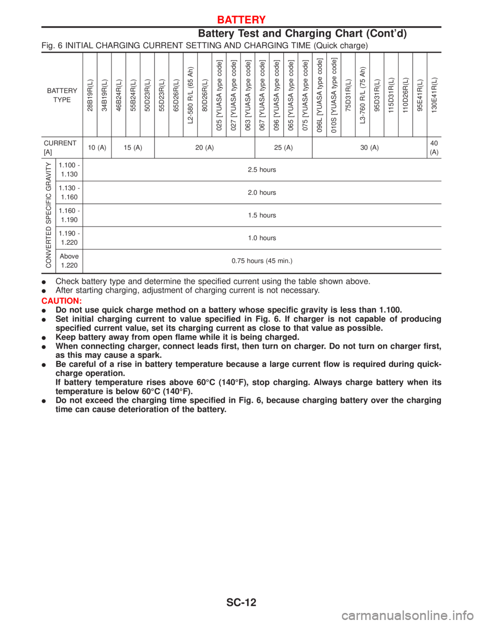
Fig. 6 INITIAL CHARGING CURRENT SETTING AND CHARGING TIME (Quick charge)
BATTERY
TYPE
28B19R(L)
34B19R(L)
46B24R(L)
55B24R(L)
50D23R(L)
55D23R(L)
65D26R(L)
L2-580 R/L (65 Ah)
80D26R(L)
025 [YUASA type code]
027 [YUASA type code]
063 [YUASA type code]
067 [YUASA type code]
096 [YUASA type code]
065 [YUASA type code]
075 [YUASA type code]
096L [YUASA type code]
010S [YUASA type code]
75D31R(L)
L3-760 R/L (75 Ah)
95D31R(L)
115D31R(L)
110D26R(L)
95E41R(L)
130E41R(L)
CURRENT
[A]10 (A) 15 (A) 20 (A) 25 (A) 30 (A)40
(A)
CONVERTED SPECIFIC GRAVITY
1.100 -
1.1302.5 hours
1.130 -
1.1602.0 hours
1.160 -
1.1901.5 hours
1.190 -
1.2201.0 hours
Above
1.2200.75 hours (45 min.)
ICheck battery type and determine the specified current using the table shown above.
IAfter starting charging, adjustment of charging current is not necessary.
CAUTION:
IDo not use quick charge method on a battery whose specific gravity is less than 1.100.
ISet initial charging current to value specified in Fig. 6. If charger is not capable of producing
specified current value, set its charging current as close to that value as possible.
IKeep battery away from open flame while it is being charged.
IWhen connecting charger, connect leads first, then turn on charger. Do not turn on charger first,
as this may cause a spark.
IBe careful of a rise in battery temperature because a large current flow is required during quick-
charge operation.
If battery temperature rises above 60ÉC (140ÉF), stop charging. Always charge battery when its
temperature is below 60ÉC (140ÉF).
IDo not exceed the charging time specified in Fig. 6, because charging battery over the charging
time can cause deterioration of the battery.
BATTERY
Battery Test and Charging Chart (Cont'd)
SC-12