2002 NISSAN TERRANO stop start
[x] Cancel search: stop startPage 764 of 1767
Diagnostic Procedure
INSPECTION START
(Stop lamp switch circuit)
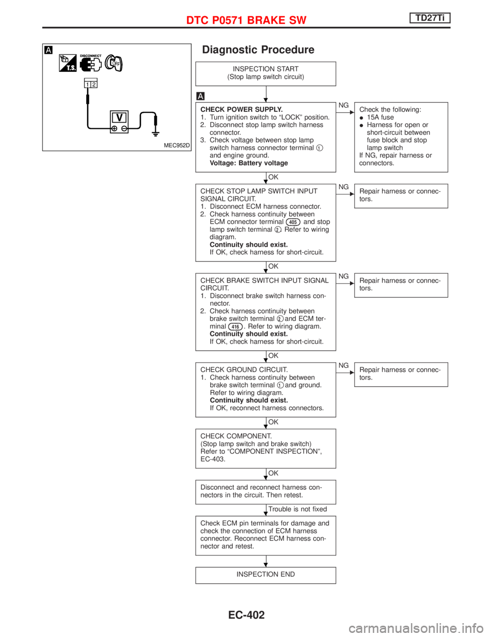
CHECK POWER SUPPLY.
1. Turn ignition switch to ªLOCKº position.
2. Disconnect stop lamp switch harness
connector.
3. Check voltage between stop lamp
switch harness connector terminalq
1and engine ground.
Voltage: Battery voltage
OK
ENG
Check the following:
I15A fuse
IHarness for open or
short-circuit between
fuse block and stop
lamp switch
If NG, repair harness or
connectors.
CHECK STOP LAMP SWITCH INPUT
SIGNAL CIRCUIT.
1. Disconnect ECM harness connector.
2. Check harness continuity between
ECM connector terminal
405and stop
lamp switch terminalq2. Refer to wiring
diagram.
Continuity should exist.
If OK, check harness for short-circuit.
OK
ENG
Repair harness or connec-
tors.
CHECK BRAKE SWITCH INPUT SIGNAL
CIRCUIT.
1. Disconnect brake switch harness con-
nector.
2. Check harness continuity between
brake switch terminalq
2and ECM ter-
minal416. Refer to wiring diagram.
Continuity should exist.
If OK, check harness for short-circuit.
OK
ENG
Repair harness or connec-
tors.
CHECK GROUND CIRCUIT.
1. Check harness continuity between
brake switch terminalq
1and ground.
Refer to wiring diagram.
Continuity should exist.
If OK, reconnect harness connectors.
OK
ENG
Repair harness or connec-
tors.
CHECK COMPONENT.
(Stop lamp switch and brake switch)
Refer to ªCOMPONENT INSPECTIONº,
EC-403.
OK
Disconnect and reconnect harness con-
nectors in the circuit. Then retest.
Trouble is not fixed
Check ECM pin terminals for damage and
check the connection of ECM harness
connector. Reconnect ECM harness con-
nector and retest.
INSPECTION END
MEC952D
H
H
H
H
H
H
H
H
DTC P0571 BRAKE SWTD27Ti
EC-402
Page 793 of 1767
System Description
EGR CONTROL
Camshaft position sensor (TDC)EEngine speed
ECMEEGRC-solenoid valve A
Mass air flow sensorEMass air flowEEGRC-solenoid valve B
Engine coolant temperature sensorEEngine coolant temperatureEThrottle control solenoid valve
Ignition switchEStart signal
Atmospheric pressure sensor
EAtmospheric pressure
Air conditioner switch
EAir conditioner ªONº signal
The ECM receives signals sent from the engine coolant tempera-
ture sensor, crankshaft position sensor (TDC), ignition switch etc.
to determine engine speed and operating conditions. Based on
these signals, the ECM controls EGRC-solenoid valve (A and B)
operation and throttle solenoid valve operation.
The EGR control stops when engine coolant temperature is below
45ÉC (113ÉF), at idling, at starting and when the system compo-
nents and engine speed signals are disordered.
Engine coolant
temperature
ÉC (ÉF)LoadEGRC-solenoid valve
Throttle control
solenoid valveEGR valveThrottle control
valveAmount of EGR
gas
AB
Below 45 (113) AnyOFF
(Closed)OFF
(Closed)OFF
(Closed)Fully closed Fully open Ð
Above 45 (113)Low loadON
(Open)ON
(Open)ON
(Open)Fully open Closed Large
Medium load-1ON
(Open)ON
(Open)OFF
(Closed)Fully open Fully open Medium
Medium load-2ON
(Open)OFF
(Closed)OFF
(Closed)Half open Fully open Small
High loadOFF
(Closed)OFF
(Closed)OFF
(Closed)Fully closed Fully open Ð
Component Description
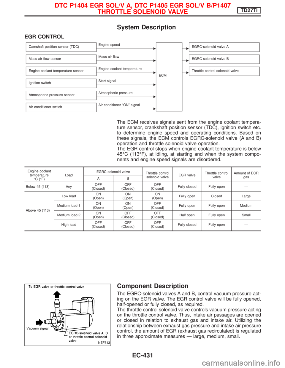
The EGRC-solenoid valves A and B, control vacuum pressure act-
ing on the EGR valve. The EGR control valve will be fully opened,
half-opened or fully closed, as required.
The throttle control solenoid valve controls vacuum pressure acting
on the throttle control valve. Thus, intake air passages are opened
or closed in relation to exhaust gas and intake air. Utilizing the
relationship between exhaust gas pressure and intake air pressure
control, the amount of EGR (exhaust gas recirculated) is regulated
in three approximate measures Ð large, medium, small.
NEF513
DTC P1404 EGR SOL/V A, DTC P1405 EGR SOL/V B/P1407
THROTTLE SOLENOID VALVETD27Ti
EC-431
Page 845 of 1767
Operation
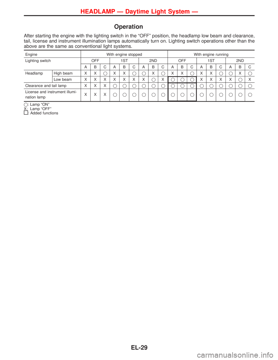
After starting the engine with the lighting switch in the ªOFFº position, the headlamp low beam and clearance,
tail, license and instrument illumination lamps automatically turn on. Lighting switch operations other than the
above are the same as conventional light systems.
Engine With engine stopped With engine running
Lighting switch OFF 1ST 2ND OFF 1ST 2ND
ABCABCABCABCABCABC
Headlamp High beam X XqXXqqXqXXqXXqqXq
Low beamXXXXXXXqXqqqXXXXqX
Clearance and tail lamp X X Xqqqqqqqqqqqqqqq
License and instrument illumi-
nation lampXXXqqqqqqqqqqqqqqq
q: Lamp ªONº
X: Lamp ªOFFº
: Added functions
HEADLAMP Ð Daytime Light System Ð
EL-29
Page 896 of 1767
Fuel Tank Gauge Unit Check
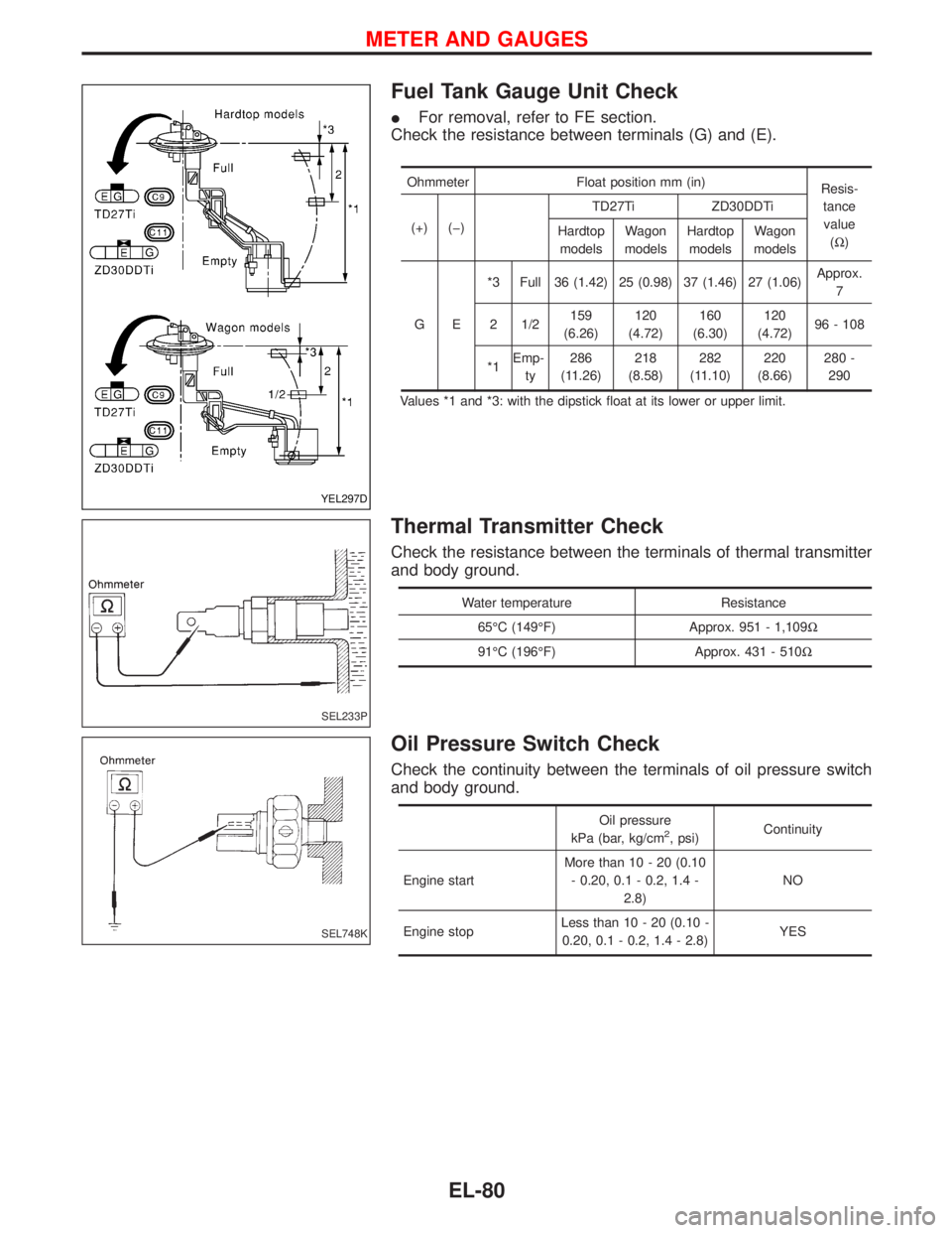
IFor removal, refer to FE section.
Check the resistance between terminals (G) and (E).
Ohmmeter Float position mm (in)
Resis-
tance
value
(W) (+) (þ)TD27Ti ZD30DDTi
Hardtop
modelsWagon
modelsHardtop
modelsWagon
models
GE*3 Full 36 (1.42) 25 (0.98) 37 (1.46) 27 (1.06)Approx.
7
2 1/2159
(6.26)120
(4.72)160
(6.30)120
(4.72)96 - 108
*1Emp-
ty286
(11.26)218
(8.58)282
(11.10)220
(8.66)280 -
290
Values *1 and *3: with the dipstick float at its lower or upper limit.
Thermal Transmitter Check
Check the resistance between the terminals of thermal transmitter
and body ground.
Water temperature Resistance
65ÉC (149ÉF) Approx. 951 - 1,109W
91ÉC (196ÉF) Approx. 431 - 510W
Oil Pressure Switch Check
Check the continuity between the terminals of oil pressure switch
and body ground.
Oil pressure
kPa (bar, kg/cm2, psi)Continuity
Engine startMore than 10 - 20 (0.10
- 0.20, 0.1 - 0.2, 1.4 -
2.8)NO
Engine stopLess than 10 - 20 (0.10 -
0.20, 0.1 - 0.2, 1.4 - 2.8)YES
YEL297D
SEL233P
SEL748K
METER AND GAUGES
EL-80
Page 1047 of 1767
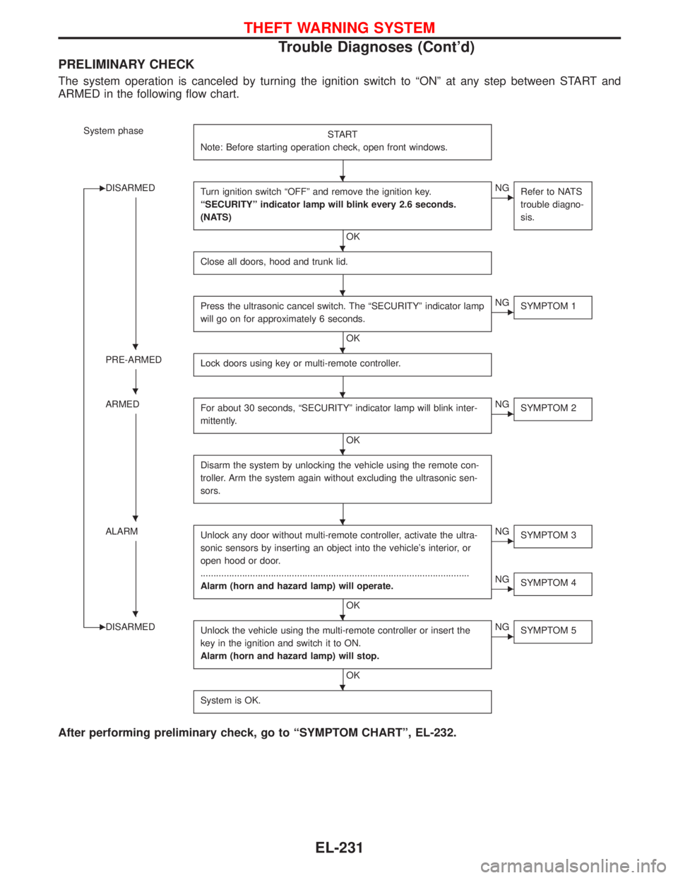
PRELIMINARY CHECK
The system operation is canceled by turning the ignition switch to ªONº at any step between START and
ARMED in the following flow chart.
System phase
START
Note: Before starting operation check, open front windows.
EDISARMED
Turn ignition switch ªOFFº and remove the ignition key.
ªSECURITYº indicator lamp will blink every 2.6 seconds.
(NATS)
OK
ENG
Refer to NATS
trouble diagno-
sis.
Close all doors, hood and trunk lid.
Press the ultrasonic cancel switch. The ªSECURITYº indicator lamp
will go on for approximately 6 seconds.
OK
ENG
SYMPTOM 1
PRE-ARMED
Lock doors using key or multi-remote controller.
ARMED
For about 30 seconds, ªSECURITYº indicator lamp will blink inter-
mittently.
OK
ENG
SYMPTOM 2
Disarm the system by unlocking the vehicle using the remote con-
troller. Arm the system again without excluding the ultrasonic sen-
sors.
ALARM
Unlock any door without multi-remote controller, activate the ultra-
sonic sensors by inserting an object into the vehicle's interior, or
open hood or door.
.......................................................................................................
Alarm (horn and hazard lamp) will operate.
OK
ENG
SYMPTOM 3
ENG
SYMPTOM 4
EDISARMED
Unlock the vehicle using the multi-remote controller or insert the
key in the ignition and switch it to ON.
Alarm (horn and hazard lamp) will stop.
OK
ENG
SYMPTOM 5
System is OK.
After performing preliminary check, go to ªSYMPTOM CHARTº, EL-232.
H
H
H
HH
HH
H
HH
HH
H
THEFT WARNING SYSTEM
Trouble Diagnoses (Cont'd)
EL-231
Page 1108 of 1767
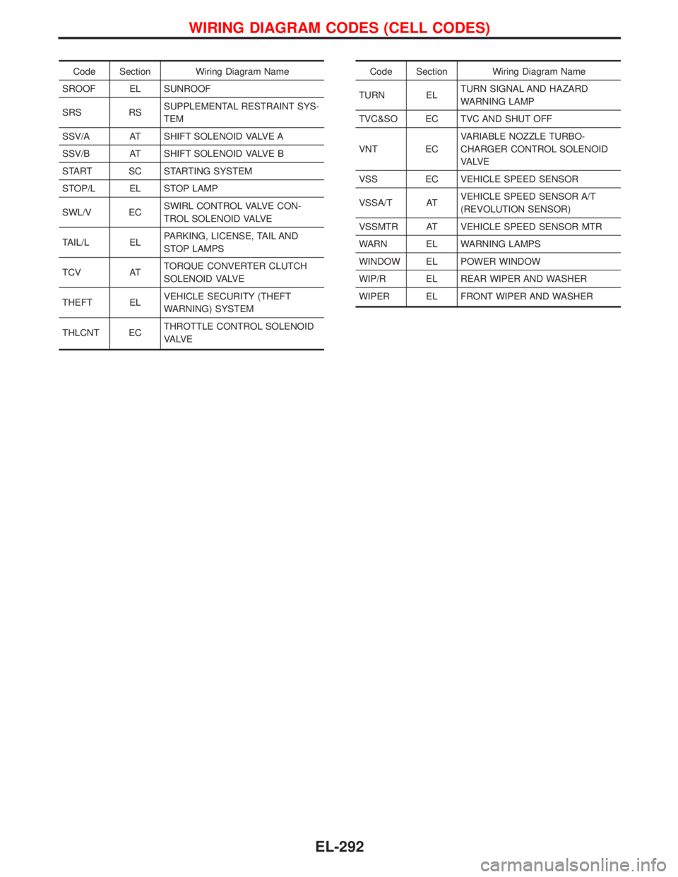
Code Section Wiring Diagram Name
SROOF EL SUNROOF
SRS RSSUPPLEMENTAL RESTRAINT SYS-
TEM
SSV/A AT SHIFT SOLENOID VALVE A
SSV/B AT SHIFT SOLENOID VALVE B
START SC STARTING SYSTEM
STOP/L EL STOP LAMP
SWL/V ECSWIRL CONTROL VALVE CON-
TROL SOLENOID VALVE
TAIL/L ELPARKING, LICENSE, TAIL AND
STOP LAMPS
TCV ATTORQUE CONVERTER CLUTCH
SOLENOID VALVE
THEFT ELVEHICLE SECURITY (THEFT
WARNING) SYSTEM
THLCNT ECTHROTTLE CONTROL SOLENOID
VA LV ECode Section Wiring Diagram Name
TURN ELTURN SIGNAL AND HAZARD
WARNING LAMP
TVC&SO EC TVC AND SHUT OFF
VNT ECVARIABLE NOZZLE TURBO-
CHARGER CONTROL SOLENOID
VA LV E
VSS EC VEHICLE SPEED SENSOR
VSSA/T ATVEHICLE SPEED SENSOR A/T
(REVOLUTION SENSOR)
VSSMTR AT VEHICLE SPEED SENSOR MTR
WARN EL WARNING LAMPS
WINDOW EL POWER WINDOW
WIP/R EL REAR WIPER AND WASHER
WIPER EL FRONT WIPER AND WASHER
WIRING DIAGRAM CODES (CELL CODES)
EL-292
Page 1144 of 1767
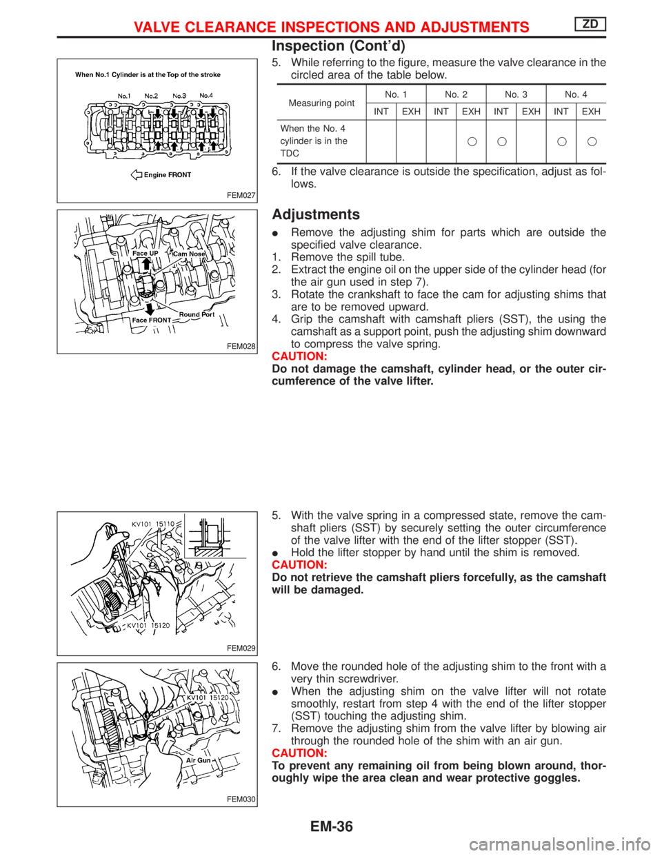
5. While referring to the figure, measure the valve clearance in the
circled area of the table below.
Measuring pointNo. 1 No. 2 No. 3 No. 4
INT EXH INT EXH INT EXH INT EXH
When the No. 4
cylinder is in the
TDCqq qq
6. If the valve clearance is outside the specification, adjust as fol-
lows.
Adjustments
IRemove the adjusting shim for parts which are outside the
specified valve clearance.
1. Remove the spill tube.
2. Extract the engine oil on the upper side of the cylinder head (for
the air gun used in step 7).
3. Rotate the crankshaft to face the cam for adjusting shims that
are to be removed upward.
4. Grip the camshaft with camshaft pliers (SST), the using the
camshaft as a support point, push the adjusting shim downward
to compress the valve spring.
CAUTION:
Do not damage the camshaft, cylinder head, or the outer cir-
cumference of the valve lifter.
5. With the valve spring in a compressed state, remove the cam-
shaft pliers (SST) by securely setting the outer circumference
of the valve lifter with the end of the lifter stopper (SST).
IHold the lifter stopper by hand until the shim is removed.
CAUTION:
Do not retrieve the camshaft pliers forcefully, as the camshaft
will be damaged.
6. Move the rounded hole of the adjusting shim to the front with a
very thin screwdriver.
IWhen the adjusting shim on the valve lifter will not rotate
smoothly, restart from step 4 with the end of the lifter stopper
(SST) touching the adjusting shim.
7. Remove the adjusting shim from the valve lifter by blowing air
through the rounded hole of the shim with an air gun.
CAUTION:
To prevent any remaining oil from being blown around, thor-
oughly wipe the area clean and wear protective goggles.
FEM027
FEM028
FEM029
FEM030
VALVE CLEARANCE INSPECTIONS AND ADJUSTMENTSZD
Inspection (Cont'd)
EM-36
Page 1340 of 1767
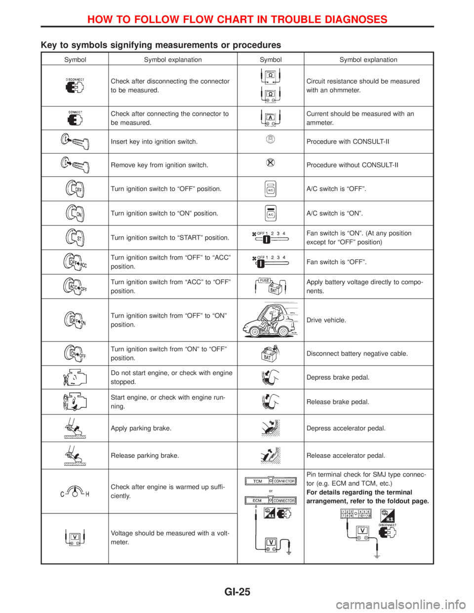
Key to symbols signifying measurements or procedures
Symbol Symbol explanation Symbol Symbol explanation
Check after disconnecting the connector
to be measured.Circuit resistance should be measured
with an ohmmeter.
Check after connecting the connector to
be measured.Current should be measured with an
ammeter.
Insert key into ignition switch.Procedure with CONSULT-II
Remove key from ignition switch.Procedure without CONSULT-II
Turn ignition switch to ªOFFº position.A/C switch is ªOFFº.
Turn ignition switch to ªONº position.A/C switch is ªONº.
Turn ignition switch to ªSTARTº position.Fan switch is ªONº. (At any position
except for ªOFFº position)
Turn ignition switch from ªOFFº to ªACCº
position.Fan switch is ªOFFº.
Turn ignition switch from ªACCº to ªOFFº
position.Apply battery voltage directly to compo-
nents.
Turn ignition switch from ªOFFº to ªONº
position.Drive vehicle.
Turn ignition switch from ªONº to ªOFFº
position.Disconnect battery negative cable.
Do not start engine, or check with engine
stopped.Depress brake pedal.
Start engine, or check with engine run-
ning.Release brake pedal.
Apply parking brake.Depress accelerator pedal.
Release parking brake.Release accelerator pedal.
Check after engine is warmed up suffi-
ciently.
Pin terminal check for SMJ type connec-
tor (e.g. ECM and TCM, etc.)
For details regarding the terminal
arrangement, refer to the foldout page.
Voltage should be measured with a volt-
meter.
HOW TO FOLLOW FLOW CHART IN TROUBLE DIAGNOSES
GI-25