2002 NISSAN TERRANO stop start
[x] Cancel search: stop startPage 12 of 1767
Shift Mechanism
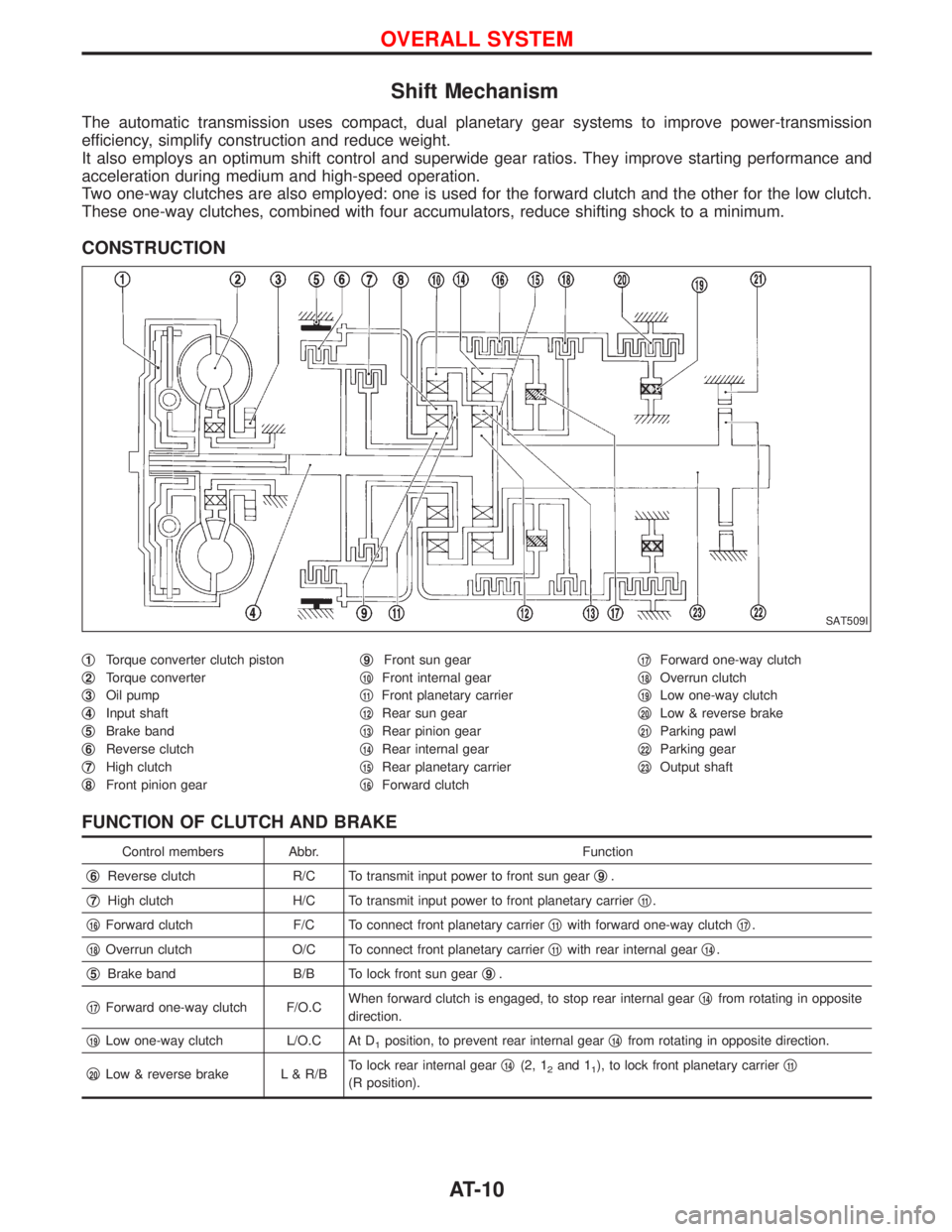
The automatic transmission uses compact, dual planetary gear systems to improve power-transmission
efficiency, simplify construction and reduce weight.
It also employs an optimum shift control and superwide gear ratios. They improve starting performance and
acceleration during medium and high-speed operation.
Two one-way clutches are also employed: one is used for the forward clutch and the other for the low clutch.
These one-way clutches, combined with four accumulators, reduce shifting shock to a minimum.
CONSTRUCTION
q1Torque converter clutch piston
q
2Torque converter
q
3Oil pump
q
4Input shaft
q
5Brake band
q
6Reverse clutch
q
7High clutch
q
8Front pinion gearq
9Front sun gear
q
10Front internal gear
q
11Front planetary carrier
q
12Rear sun gear
q
13Rear pinion gear
q
14Rear internal gear
q
15Rear planetary carrier
q
16Forward clutchq
17Forward one-way clutch
q
18Overrun clutch
q
19Low one-way clutch
q
20Low & reverse brake
q
21Parking pawl
q
22Parking gear
q
23Output shaft
FUNCTION OF CLUTCH AND BRAKE
Control members Abbr. Function
q
6Reverse clutch R/C To transmit input power to front sun gearq9.
q
7High clutch H/C To transmit input power to front planetary carrierq11.
q
16Forward clutch F/C To connect front planetary carrierq11with forward one-way clutchq17.
q
18Overrun clutch O/C To connect front planetary carrierq11with rear internal gearq14.
q
5Brake band B/B To lock front sun gearq9.
q
17Forward one-way clutch F/O.CWhen forward clutch is engaged, to stop rear internal gearq14from rotating in opposite
direction.
q
19Low one-way clutch L/O.C At D1position, to prevent rear internal gearq14from rotating in opposite direction.
q
20Low & reverse brake L & R/BTo lock rear internal gearq14(2, 12and 11), to lock front planetary carrierq11
(R position).
SAT509I
OVERALL SYSTEM
AT-10
Page 29 of 1767
A/T Fluid Check
FLUID LEAKAGE CHECK
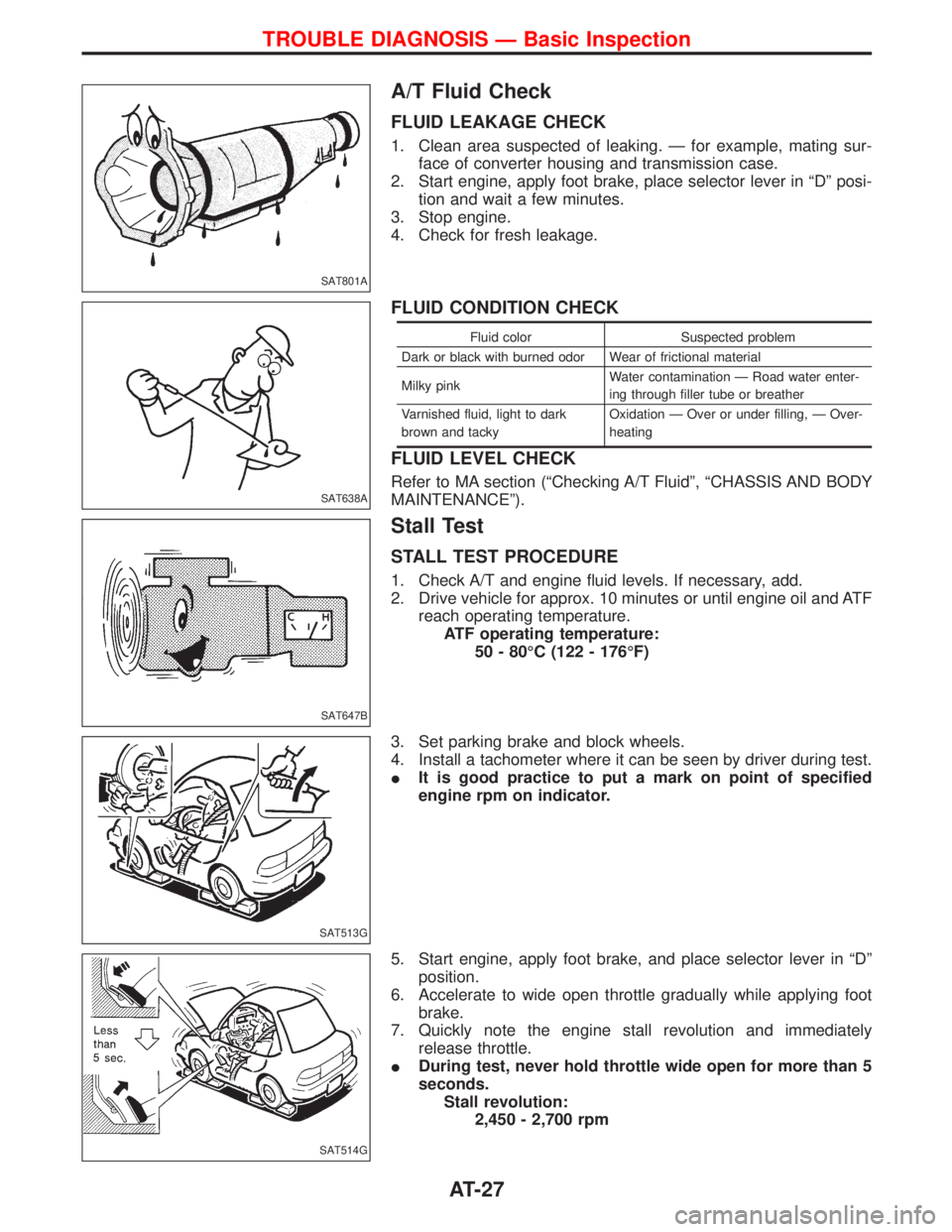
1. Clean area suspected of leaking. Ð for example, mating sur-
face of converter housing and transmission case.
2. Start engine, apply foot brake, place selector lever in ªDº posi-
tion and wait a few minutes.
3. Stop engine.
4. Check for fresh leakage.
FLUID CONDITION CHECK
Fluid color Suspected problem
Dark or black with burned odor Wear of frictional material
Milky pinkWater contamination Ð Road water enter-
ing through filler tube or breather
Varnished fluid, light to dark
brown and tackyOxidation Ð Over or under filling, Ð Over-
heating
FLUID LEVEL CHECK
Refer to MA section (ªChecking A/T Fluidº, ªCHASSIS AND BODY
MAINTENANCEº).
Stall Test
STALL TEST PROCEDURE
1. Check A/T and engine fluid levels. If necessary, add.
2. Drive vehicle for approx. 10 minutes or until engine oil and ATF
reach operating temperature.
ATF operating temperature:
50 - 80ÉC (122 - 176ÉF)
3. Set parking brake and block wheels.
4. Install a tachometer where it can be seen by driver during test.
IIt is good practice to put a mark on point of specified
engine rpm on indicator.
5. Start engine, apply foot brake, and place selector lever in ªDº
position.
6. Accelerate to wide open throttle gradually while applying foot
brake.
7. Quickly note the engine stall revolution and immediately
release throttle.
IDuring test, never hold throttle wide open for more than 5
seconds.
Stall revolution:
2,450 - 2,700 rpm
SAT801A
SAT638A
SAT647B
SAT513G
SAT514G
TROUBLE DIAGNOSIS Ð Basic Inspection
AT-27
Page 39 of 1767
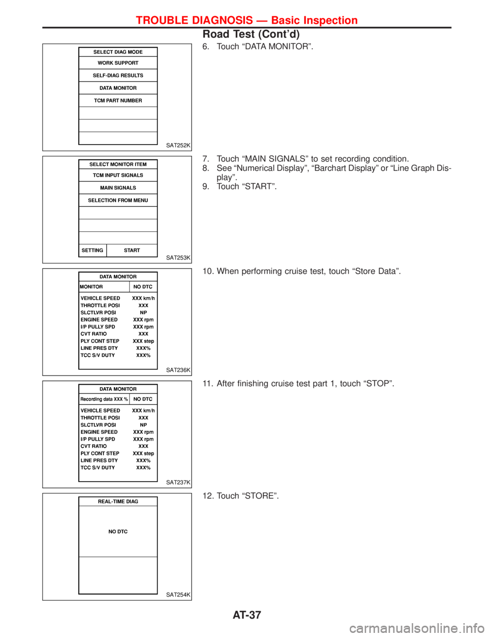
6. Touch ªDATA MONITORº.
7. Touch ªMAIN SIGNALSº to set recording condition.
8. See ªNumerical Displayº, ªBarchart Displayº or ªLine Graph Dis-
playº.
9. Touch ªSTARTº.
10. When performing cruise test, touch ªStore Dataº.
11. After finishing cruise test part 1, touch ªSTOPº.
12. Touch ªSTOREº.
SAT252K
SAT253K
SAT236K
SAT237K
SAT254K
TROUBLE DIAGNOSIS Ð Basic Inspection
Road Test (Cont'd)
AT-37
Page 43 of 1767
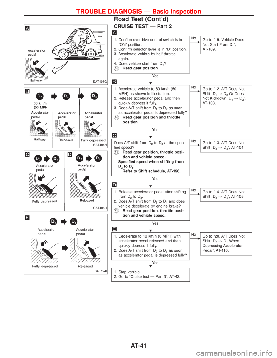
CRUISE TEST Ð Part 2
1. Confirm overdrive control switch is in
ªONº position.
2. Confirm selector lever is in ªDº position.
3. Accelerate vehicle by half throttle
again.
4. Does vehicle start from D
1?
Read gear position.
Ye s
ENo
Go to ª19. Vehicle Does
Not Start From D
1º,
AT-109.
1. Accelerate vehicle to 80 km/h (50
MPH) as shown in illustration.
2. Release accelerator pedal and then
quickly depress it fully.
3. Does A/T shift from D
4to D2as soon
as accelerator pedal is depressed fully?
Read gear position and throttle
position.
Ye s
ENo
Go to ª12. A/T Does Not
Shift: D
1,D2Or Does
Not Kickdown: D
4,D2º,
AT-103.
Does A/T shift from D2to D3at the speci-
fied speed?
Read gear position, throttle posi-
tion and vehicle speed.
Specified speed when shifting from
D
2to D3:
Refer to Shift schedule, AT-196.
Ye s
ENo
Go to ª13. A/T Does Not
Shift: D
2,D3º, AT-104.
1. Release accelerator pedal after shifting
from D
2to D3.
2. Does A/T shift from D
3to D4and does
vehicle decelerate by engine brake?
Read gear position, throttle posi-
tion and vehicle speed.
Ye s
ENo
Go to ª14. A/T Does Not
Shift: D
3,D4º, AT-105.
1. Decelerate to 10 km/h (6 MPH) with
accelerator pedal released and then
quickly depress it fully.
2. Does A/T shift from D
2to D1as soon
as accelerator pedal is depressed fully?
Ye s
ENo
Go to ª20. A/T Does Not
Shift: D
2,D1When
Depressing Accelerator
Pedalº, AT-110.
1. Stop vehicle.
2. Go to ªCruise test Ð Part 3º, AT-42.
SAT495G
SAT404H
SAT405H
SAT124I
H
H
H
H
H
TROUBLE DIAGNOSIS Ð Basic Inspection
Road Test (Cont'd)
AT-41
Page 45 of 1767
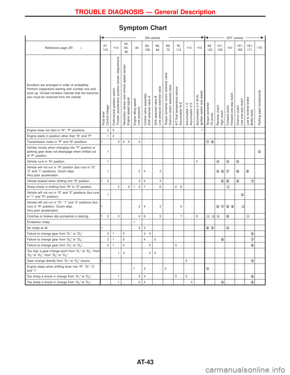
Symptom Chart
FON vehicleEFOFF vehicleE
Reference page (AT- )27,
11 511 454,
60,
803063,
13966,
8469,
7276,
11 311 3 11 369,
123151,
155157157,
165161,
171175
Numbers are arranged in order of probability.
Perform inspections starting with number one and
work up. Circled numbers indicate that the transmis-
sion must be removed from the vehicle.
Fluid level
Control linkage
Park/neutral position switch
Throttle (accelerator) position sensor (Adjustment)
Revolution sensor and vehicle speed sensor
Engine speed signal
Engine idling speed
Line pressure
Control valve assembly
Shift solenoid valve A
Shift solenoid valve B
Line pressure solenoid valve
Torque converter clutch solenoid valve
Overrun clutch solenoid valve
A/T fluid temperature sensor
Accumulator N-D
Accumulator 1-2
Accumulator 2-3
Accumulator 3-4 (N-R)
Ignition switch and starter
Torque converter
Oil pump
Reverse clutch
High clutch
Forward clutch
Forward one-way clutch
Overrun clutch
Low one-way clutch
Low & reverse brake
Brake band
Parking pawl components
Engine does not start in ªNº, ªPº positions. . 2 3................1.......... .
Engine starts in position other than ªNº and ªPº. . 1 2................. .......... .
Transmission noise in ªPº and ªNº positions. 1 . . 3 4 5 . 2............q
7q6........ .
Vehicle moves when changing into ªPº position or
parking gear does not disengage when shifted out
of ªPº position.. 1.................. ..........q
2
Vehicle runs in ªNº position. . 1................2. ..q4.q3.q5... .
Vehicle will not run in ªRº position (but runs in ªDº,
ª2º and ª1º positions). Clutch slips.
Very poor acceleration.. 1.....24..3........ ..q
5q6q7.q8.q9..
Vehicle braked when shifting into ªRº position. 1 2.....35..4........ ...q
6q8.q9..q7.
Sharp shock in shifting from ªNº to ªDº position. . . . 2 .5137 . . 6 . . 48.... ....q
10..... .
Vehicle will not run in ªDº and ª2º positions (but runs
in ª1º and ªRº position).. 1.................. .......q
2.. .
Vehicle will not run in ªDº, ª1º and ª2º positions (but
runs in ªRº position). Clutch slips.
Very poor acceleration.1 ......24..3...5.... ..q
6q7q8q9.q10.. .
Clutches or brakes slip somewhat in starting. 1 2 . 3 . . . 4 6 . . 5 . . . 7 . . 8 .q
13q12q10.q9...q11..
Excessive creep. ......1............. .......... .
No creep at all. 1......23...........q
6q5..q4..... .
Failure to change gear from ªD
1ºtoªD2º. . 21.5...43.......... .........q6.
Failure to change gear from ªD
2ºtoªD3º. . 21.5...4.3......... ...q6.....q7.
Failure to change gear from ªD
3ºtoªD4º. . 21.4....3....5..... .........q6.
Too high a gear change point from ªD
1ºtoªD2º, from
ªD2ºtoªD3º, from ªD3ºtoªD4º.. ..12....34......... .......... .
Gear change directly from ªD
1ºtoªD3º occurs. 1...............2... .........q3.
Engine stops when shifting lever into ªRº, ªDº, ª2º
and ª1º.. .....1.3...2.......q
4......... .
Too sharp a shock in change from ªD
1ºtoªD2º. . ..1...24.....5.3... .........q6.
Too sharp a shock in change from ªD
2ºtoªD3º. . ..1...24........3.. ...q5.....q6.
TROUBLE DIAGNOSIS Ð General Description
AT-43
Page 47 of 1767
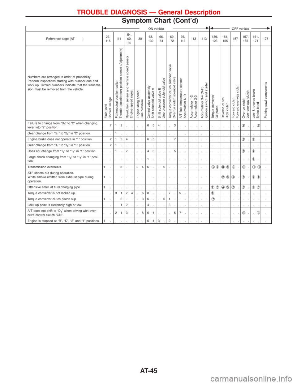
FON vehicleEFOFF vehicleE
Reference page (AT- )27,
11 511 454,
60,
803063,
13966,
8469,
7276,
11 311 3 11 3139,
123151,
155157157,
165161,
171175
Numbers are arranged in order of probability.
Perform inspections starting with number one and
work up. Circled numbers indicate that the transmis-
sion must be removed from the vehicle.
Fluid level
Control linkage
Park/neutral position switch
Throttle (accelerator) position sensor (Adjustment)
Revolution sensor and vehicle speed sensor
Engine speed signal
Engine idling speed
Line pressure
Control valve assembly
Shift solenoid valve A
Shift solenoid valve B
Line pressure solenoid valve
Torque converter clutch solenoid valve
Overrun clutch solenoid valve
A/T fluid temperature sensor
Accumulator N-D
Accumulator 1-2
Accumulator 2-3
Accumulator 3-4 (N-R)
Ignition switch and starter
Torque converter
Oil pump
Reverse clutch
High clutch
Forward clutch
Forward one-way clutch
Overrun clutch
Low one-way clutch
Low & reverse brake
Brake band
Parking pawl components
Failure to change from ªD3º to ª2º when changing
lever into ª2º position.. 712....654..3...... ......q9..q8.
Gear change from ª2
1ºtoª22º in ª2º position. . . 1................. .......... .
Engine brake does not operate in ª1º position. .2134 . . . 65 . . . 7...... ......q
8.q9..
Gear change from ª1
1ºtoª12º in ª1º position. . 2 1................. .......... .
Does not change from ª1
2ºtoª11º in ª1º position. . . 1 . 2 . . . 4 3 . . . 5...... ......q6.q7..
Large shock changing from ª1
2ºtoª11º in ª1º posi-
tion.. .......1........... ........q2..
Transmission overheats. 1 . . 3 . . 2 4 6 . . 5........q
14q7q8q9q11.q12.q13q10.
ATF shoots out during operation.
White smoke emitted from exhaust pipe during
operation.1 ................... ..q
2q3q5.q6.q7q4.
Offensive smell at fluid charging pipe. 1...................q
2q3q4q5q7.q8.q9q6.
Torque converter is not locked up. . .3124 . 68 . . . 7 . 5.....q
9......... .
Torque converter clutch piston slip 1 . . 2 . . . 3 6 . . 5 4.......q
7......... .
Lock-up point is extremely high or low. . . . 1 2 . . . 4 . . . 3....... .......... .
A/T does not shift to ªD
4º when driving with over-
drive control switch ªONº.. .213..864...57..... ......q10..q9.
Engine is stopped at ªRº, ªDº, ª2º and ª1º positions. 1.......543.2....... .......... .
TROUBLE DIAGNOSIS Ð General Description
Symptom Chart (Cont'd)
AT-45
Page 215 of 1767
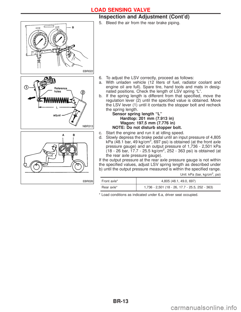
5. Bleed the air from the rear brake piping.
6. To adjust the LSV correctly, proceed as follows:
a. With unladen vehicle (12 liters of fuel, radiator coolant and
engine oil are full). Spare tire, hand tools and mats in desig-
nated positions. Check the length of LSV spring ªLº.
b. If the spring length is different from that specified, move the
regulation lever (2) until the specified value is obtained. Move
the LSV lever (1) until it contacts the stopper bolt and recheck
the spring length.
Sensor spring length ªLº
Hardtop: 201 mm (7.913 in)
Wagon: 197.5 mm (7.776 in)
NOTE: Do not disturb stopper bolt.
c. Start the engine and run it at idling speed.
d. Slowly depress the brake pedal until an input pressure of 4,805
kPa (48.1 bar, 49 kg/cm
2, 697 psi) is obtained (at the front axle
pressure gauge) and an output pressure of 1,736 - 2,501 kPa
(18 - 26 bar, 17.7 - 25.5 kg/cm
2, 252 - 363 psi) is obtained (at
the rear axle pressure gauge).
If the output pressure at the rear axle pressure gauge is not within
the specified values, adjust LSV spring length as described under
b) until the output pressure measured is within the specified range.
Unit: kPa (bar, kg/cm2, psi)
Front axle* 4,805 (48.1, 49.0, 697)
Rear axle* 1,736 - 2,501 (18 - 26, 17.7 - 25.5, 252 - 363)
* Load conditions as indicated under 6.a, driver seat occupied.
EBR022
NBR313
EBR026
LOAD SENSING VALVE
Inspection and Adjustment (Cont'd)
BR-13
Page 219 of 1767
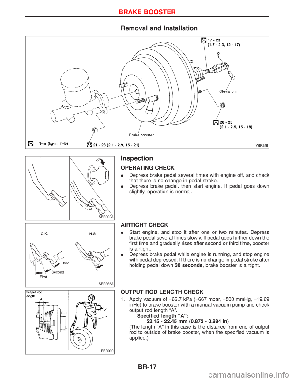
Removal and Installation
Inspection
OPERATING CHECK
IDepress brake pedal several times with engine off, and check
that there is no change in pedal stroke.
IDepress brake pedal, then start engine. If pedal goes down
slightly, operation is normal.
AIRTIGHT CHECK
IStart engine, and stop it after one or two minutes. Depress
brake pedal several times slowly. If pedal goes further down the
first time and gradually rises after second or third time, booster
is airtight.
IDepress brake pedal while engine is running, and stop engine
with pedal depressed. If there is no change in pedal stroke after
holding pedal down30 seconds, brake booster is airtight.
OUTPUT ROD LENGTH CHECK
1. Apply vacuum of þ66.7 kPa (þ667 mbar, þ500 mmHg, þ19.69
inHg) to brake booster with a manual vacuum pump and check
output rod length ªAº.
Specified length ªAº:
22.15 - 22.45 mm (0.872 - 0.884 in)
(The length ªAº in this case is the distance from end of output
rod to outside of brake booster, when the specified vacuum is
applied.)
YBR259
SBR002A
SBR365A
EBR090
BRAKE BOOSTER
BR-17