2002 NISSAN TERRANO stop start
[x] Cancel search: stop startPage 691 of 1767
![NISSAN TERRANO 2002 Service Repair Manual SELF-DIAGNOSTIC MODE
Regarding items detected in ªSELF-DIAG RESULTSº mode, refer to ªTROUBLE DIAGNOSIS Ð INDEXº,
EC-293.
DATA MONITOR MODE
Monitored item
[Unit]ECM
input
signalsMain
signalsDescri NISSAN TERRANO 2002 Service Repair Manual SELF-DIAGNOSTIC MODE
Regarding items detected in ªSELF-DIAG RESULTSº mode, refer to ªTROUBLE DIAGNOSIS Ð INDEXº,
EC-293.
DATA MONITOR MODE
Monitored item
[Unit]ECM
input
signalsMain
signalsDescri](/manual-img/5/57393/w960_57393-690.png)
SELF-DIAGNOSTIC MODE
Regarding items detected in ªSELF-DIAG RESULTSº mode, refer to ªTROUBLE DIAGNOSIS Ð INDEXº,
EC-293.
DATA MONITOR MODE
Monitored item
[Unit]ECM
input
signalsMain
signalsDescription Remarks
CKPS×RPM
(TDC) [rpm]
qq
IThe engine speed computed from the
crankshaft position sensor (TDC) signal
is displayed.
CMPS×RPM -
PUMP [rpm]
qqIThe engine speed computed from the
needle lift sensor signal is displayed.
COOLAN TEMP/S
[ÉC] or [ÉF]
qq
IThe engine coolant temperature (deter-
mined by the signal voltage of the engine
coolant temperature sensor) is displayed.IWhen the engine coolant temperature
sensor is open or short-circuited, ECM
enters fail-safe mode. The same data as
the fuel temperature is displayed.
VHCL SPEED SE
[km/h] or [mph]
qqIThe vehicle speed computed from the
vehicle speed sensor signal is displayed.
FUEL TEMP SEN
[ÉC] or [ÉF]
qq
IThe fuel temperature (determined by the
signal voltage of the fuel temperature
sensor) is displayed.
ACCEL POS SEN [V]
qqIThe accelerator position sensor signal
voltage is displayed.
OFF ACCEL POS
[ON/OFF]
qqIIndicates [ON/OFF] condition from the
accelerator position switch signal.ISignal at approximately 9É opened.
C/SLEEV POS/S [V]
qqIThe control sleeve position sensor signal
voltage is displayed.
BATTERY VOLT [V]
qqIThe power supply voltage of ECM is dis-
played.
START SIGNAL
[ON/OFF]
qqIIndicates [ON/OFF] condition from the
starter signal.IAfter starting the engine, [OFF] is dis-
played regardless of the starter signal.
AIR COND SIG
[ON/OFF]
qq
IIndicates [ON/OFF] condition of the air
conditioner switch as determined by the
air conditioner signal.
BRAKE SW
[ON/OFF]
qIIndicates [ON/OFF] condition of the stop
lamp switch.
BRAKE SW2
[ON/OFF]
qIIndicates [ON/OFF] condition of the
brake switch 2.
IGN SW
[ON/OFF]
qqIIndicates [ON/OFF] condition from igni-
tion switch.
MAS AIR/FL SE [V]
qqIThe signal voltage of the mass air flow
sensor is displayed.IWhen the engine is stopped, a certain
value is indicated.
ACT INJ TIMG [É]
q
IThe actual injection timing angle deter-
mined by the ECM (an approximate aver-
age angle between injection start and
end from TDC) is displayed.
TARGET F/INJ
[mm
3/stroke]qIThe target fuel injection quantity (deter-
mined by the ECM according to the input
signal) is indicated.
NOTE:
Any monitored item that does not match the vehicle being diagnosed is deleted from the display automatically.
ON BOARD DIAGNOSTIC SYSTEM DESCRIPTIONTD27Ti
CONSULT-II (Cont'd)
EC-329
Page 697 of 1767
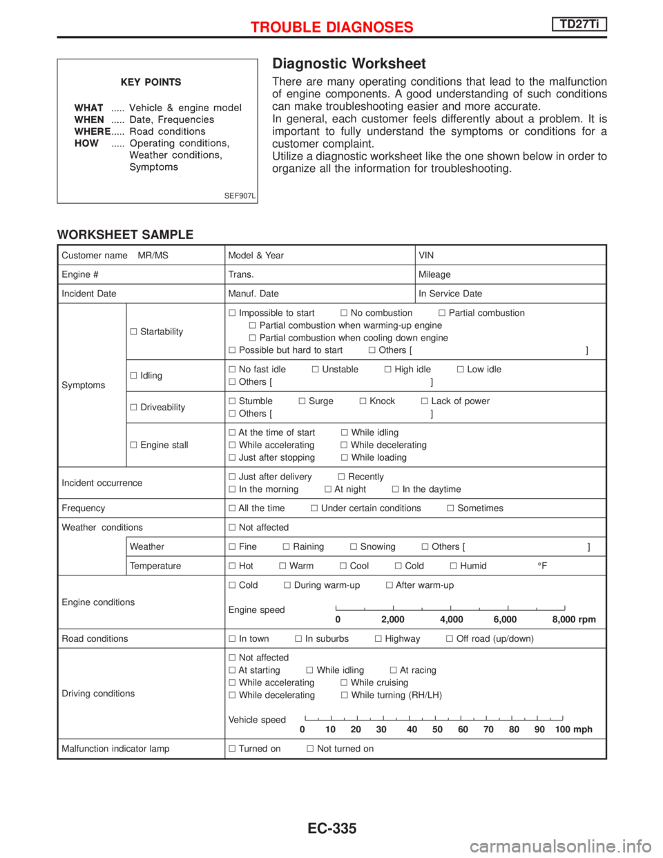
Diagnostic Worksheet
There are many operating conditions that lead to the malfunction
of engine components. A good understanding of such conditions
can make troubleshooting easier and more accurate.
In general, each customer feels differently about a problem. It is
important to fully understand the symptoms or conditions for a
customer complaint.
Utilize a diagnostic worksheet like the one shown below in order to
organize all the information for troubleshooting.
WORKSHEET SAMPLE
Customer name MR/MS Model & Year VIN
Engine # Trans. Mileage
Incident Date Manuf. Date In Service Date
SymptomslStartabilitylImpossible to startlNo combustionlPartial combustion
lPartial combustion when warming-up engine
lPartial combustion when cooling down engine
lPossible but hard to startlOthers [ ]
lIdlinglNo fast idlelUnstablelHigh idlelLow idle
lOthers [ ]
lDriveabilitylStumblelSurgelKnocklLack of power
lOthers [ ]
lEngine stalllAt the time of startlWhile idling
lWhile acceleratinglWhile decelerating
lJust after stoppinglWhile loading
Incident occurrencelJust after deliverylRecently
lIn the morninglAt nightlIn the daytime
FrequencylAll the timelUnder certain conditionslSometimes
Weather conditionslNot affected
WeatherlFinelRaininglSnowinglOthers [ ]
TemperaturelHotlWarmlCoollColdlHumid ÉF
Engine conditionslColdlDuring warm-uplAfter warm-up
Engine speed
0 2,000 4,000 6,000 8,000 rpm
Road conditionslIn townlIn suburbslHighwaylOff road (up/down)
Driving conditionslNot affected
lAt startinglWhile idlinglAt racing
lWhile acceleratinglWhile cruising
lWhile deceleratinglWhile turning (RH/LH)
Vehicle speed
0 102030 405060708090100mph
Malfunction indicator lamplTurned onlNot turned on
SEF907L
TROUBLE DIAGNOSESTD27Ti
EC-335
Page 701 of 1767
qA
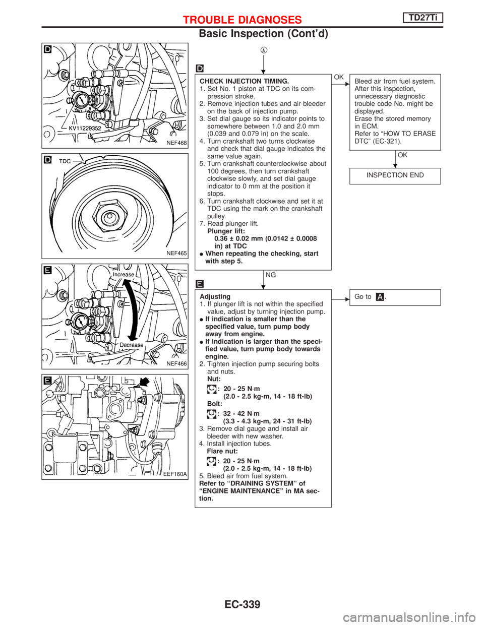
CHECK INJECTION TIMING.
1. Set No. 1 piston at TDC on its com-
pression stroke.
2. Remove injection tubes and air bleeder
on the back of injection pump.
3. Set dial gauge so its indicator points to
somewhere between 1.0 and 2.0 mm
(0.039 and 0.079 in) on the scale.
4. Turn crankshaft two turns clockwise
and check that dial gauge indicates the
same value again.
5. Turn crankshaft counterclockwise about
100 degrees, then turn crankshaft
clockwise slowly, and set dial gauge
indicator to 0 mm at the position it
stops.
6. Turn crankshaft clockwise and set it at
TDC using the mark on the crankshaft
pulley.
7. Read plunger lift.
Plunger lift:
0.36 0.02 mm (0.0142 0.0008
in) at TDC
IWhen repeating the checking, start
with step 5.
NG
EOK
Bleed air from fuel system.
After this inspection,
unnecessary diagnostic
trouble code No. might be
displayed.
Erase the stored memory
in ECM.
Refer to ªHOW TO ERASE
DTCº (EC-321).
OK
INSPECTION END
Adjusting
1. If plunger lift is not within the specified
value, adjust by turning injection pump.
IIf indication is smaller than the
specified value, turn pump body
away from engine.
IIf indication is larger than the speci-
fied value, turn pump body towards
engine.
2. Tighten injection pump securing bolts
and nuts.
Nut:
: 20-25N×m
(2.0 - 2.5 kg-m, 14 - 18 ft-lb)
Bolt:
: 32-42N×m
(3.3 - 4.3 kg-m, 24 - 31 ft-lb)
3. Remove dial gauge and install air
bleeder with new washer.
4. Install injection tubes.
Flare nut:
: 20-25N×m
(2.0 - 2.5 kg-m, 14 - 18 ft-lb)
5. Bleed air from fuel system.
Refer to ªDRAINING SYSTEMº of
ªENGINE MAINTENANCEº in MA sec-
tion.
EGo to.
NEF468
NEF465
NEF466
EEF160A
H
H
H
TROUBLE DIAGNOSESTD27Ti
Basic Inspection (Cont'd)
EC-339
Page 704 of 1767
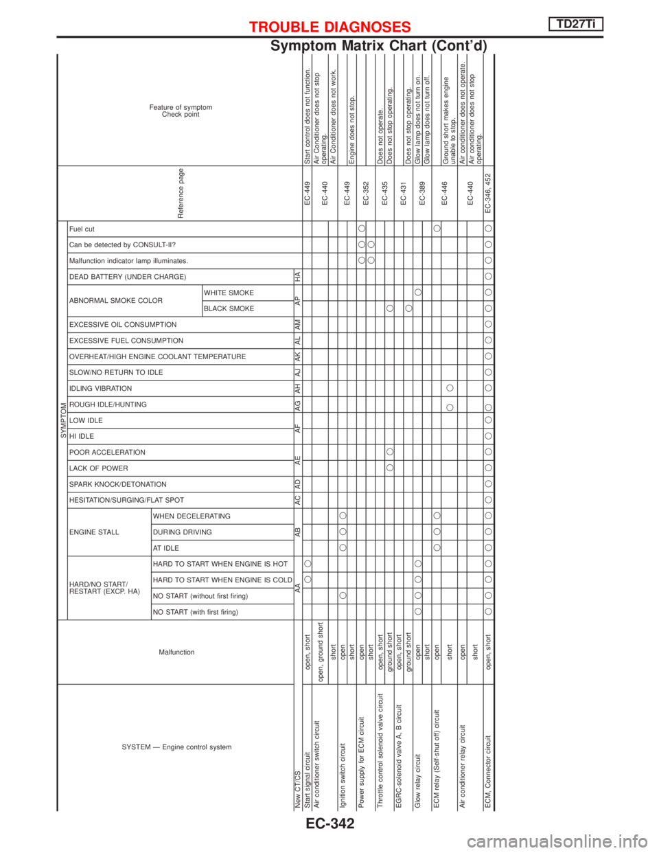
SYSTEM Ð Engine control systemMalfunction
SYMPTOM
Reference page
Feature of symptom
Check point
HARD/NO START/
RESTART (EXCP. HA) ENGINE STALL HESITATION/SURGING/FLAT SPOT SPARK KNOCK/DETONATION
LACK OF POWER
POOR ACCELERATION
HI IDLE
LOW IDLE
ROUGH IDLE/HUNTING
IDLING VIBRATION
SLOW/NO RETURN TO IDLE
OVERHEAT/HIGH ENGINE COOLANT TEMPERATURE
EXCESSIVE FUEL CONSUMPTION
EXCESSIVE OIL CONSUMPTION ABNORMAL SMOKE COLOR
DEAD BATTERY (UNDER CHARGE) Malfunction indicator lamp illuminates.
Can be detected by CONSULT-II?
Fuel cut
NO START (with first firing) NO START (without first firing)
HARD TO START WHEN ENGINE IS COLD
HARD TO START WHEN ENGINE IS HOT
AT IDLE
DURING DRIVING
WHEN DECELERATINGBLACK SMOKE WHITE SMOKE
New CT/CS AA AB AC AD AE AF AG AH AJ AK AL AM AP HA
Start signal circuit open, shortqqEC-449 Start control does not function.
Air conditioner switch circuit
open, ground short
EC-440Air Conditioner does not stop
operating.
shortAir Conditioner does not work.
Ignition switch circuit openq qqq
EC-449
shortEngine does not stop.
Power supply for ECM circuit openqqq
EC-352
shortqq
Throttle control solenoid valve circuit open, short
EC-435Does not operate.
ground shortqq qDoes not stop operating.
EGRC-solenoid valve A, B circuit open, short
EC-431
ground shortqDoes not stop operating.
Glow relay circuit openqqqqq
EC-389Glow lamp does not turn on.
shortGlow lamp does not turn off.
ECM relay (Self-shut off) circuit openqqqq
EC-446
shortqqGround short makes engine
unable to stop.
Air conditioner relay circuit open
EC-440Air conditioner does not operate.
shortAir conditioner does not stop
operating.
ECM, Connector circuit open, shortqqqqqqqqqqqqqq qqqqqqqqqqqEC-346, 452
TROUBLE DIAGNOSESTD27Ti
Symptom Matrix Chart (Cont'd)
EC-342
Page 705 of 1767
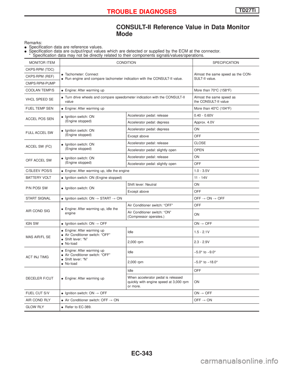
CONSULT-II Reference Value in Data Monitor
Mode
Remarks:
ISpecification data are reference values.
ISpecification data are output/input values which are detected or supplied by the ECM at the connector.
* Specification data may not be directly related to their components signals/values/operations.
MONITOR ITEM CONDITION SPECIFICATION
CKPS×RPM (TDC)
ITachometer: Connect
IRun engine and compare tachometer indication with the CONSULT-II value.Almost the same speed as the CON-
SULT-II value. CKPS×RPM (REF)
CMPS×RPM-PUMP
COOLAN TEMP/SIEngine: After warming up More than 70ÉC (158ÉF)
VHCL SPEED SEITurn drive wheels and compare speedometer indication with the CONSULT-II
valueAlmost the same speed as
the CONSULT-II value
FUEL TEMP SENIEngine: After warming up More than 40ÉC (104ÉF)
ACCEL POS SENIIgnition switch: ON
(Engine stopped)Accelerator pedal: release 0.40 - 0.60V
Accelerator pedal: depress Approx. 4.0V
FULL ACCEL SWIIgnition switch: ON
(Engine stopped)Accelerator pedal: depress ON
Except above OFF
ACCEL SW (FC)IIgnition switch: ON
(Engine stopped)Accelerator pedal: release CLOSE
Accelerator pedal: slightly open OPEN
OFF ACCEL SWIIgnition switch: ON
(Engine stopped)Accelerator pedal: release ON
Accelerator pedal: slightly open OFF
C/SLEEV POS/SIEngine: After warming up, idle the engine 1.0 - 3.5V
BATTERY VOLTIIgnition switch: ON (Engine stopped) 11 - 14V
P/N POSI SWIIgnition switch: ONShift lever: Neutral ON
Except above OFF
START SIGNALIIgnition switch: ON,START,ON OFF,ON,OFF
AIR COND SIGIEngine: After warming up, idle the
engineAir Conditioner switch: ªOFFº OFF
Air Conditioner switch: ªONº
(Compressor operates.)ON
IGN SWIIgnition switch: ON,OFF ON,OFF
MAS AIR/FL SEIEngine: After warming up
IAir Conditioner switch: ªOFFº
IShift lever: ªNº
INo-loadIdle 1.5 - 2.1V
2,000 rpm 2.3 - 2.9V
ACT INJ TIMGIEngine: After warming up
IAir Conditioner switch: ªOFFº
IShift lever: ªNº
INo-loadIdle þ5.0É to þ9.0É
2,000 rpm þ5.0É to þ18.0É
DECELER F/CUTIEngine: After warming upIdle OFF
When accelerator pedal is released
quickly with engine speed at 3,000 rpm
or more.ON
FUEL CUT S/VIIgnition switch: ON,OFF ON,OFF
AIR COND RLYIAir Conditioner switch: OFF,ON OFF,ON
GLOW RLYIRefer to EC-389.
TROUBLE DIAGNOSESTD27Ti
EC-343
Page 712 of 1767
![NISSAN TERRANO 2002 Service Repair Manual TERMI-
NAL
NO.WIRE
COLORITEM CONDITIONDATA (DC Voltage and
Pulse Signal)
347 LG/WEngine coolant tempera-
ture sensor[Engine is running]Approximately 0 - 4.8V
Output voltage varies with
engine coolant NISSAN TERRANO 2002 Service Repair Manual TERMI-
NAL
NO.WIRE
COLORITEM CONDITIONDATA (DC Voltage and
Pulse Signal)
347 LG/WEngine coolant tempera-
ture sensor[Engine is running]Approximately 0 - 4.8V
Output voltage varies with
engine coolant](/manual-img/5/57393/w960_57393-711.png)
TERMI-
NAL
NO.WIRE
COLORITEM CONDITIONDATA (DC Voltage and
Pulse Signal)
347 LG/WEngine coolant tempera-
ture sensor[Engine is running]Approximately 0 - 4.8V
Output voltage varies with
engine coolant tempera-
ture
348 Y/B Fuel temperature sensor[Engine is running]0.6-5V
Output voltage varies with
fuel temperature.
349 G/RInjection timing control
valve ground[Ignition switch ªONº]Approximately 0V
403 G/R Air conditioner switch[Engine is running]
IAir conditioner switch is ªOFFºBATTERY VOLTAGE
(11 - 14V)
[Engine is running]
IBoth air conditioner switch and blower fan switch
are ªONº
(Compressor is operating)Approximately 0.1V
405 G/Y Stop lamp switch[Ignition switch ªONº]
IBrake pedal fully releasedApproximately 0V
[Ignition switch ªONº]
IBrake pedal depressedBATTERY VOLTAGE
(11 - 14V)
416 Y/RBrake pedal position
switch[Ignition switch ªONº]
IBrake pedal fully releasedBATTERY VOLTAGE
(11 - 14V)
[Ignition switch ªONº]
IBrake pedal depressedApproximately 0V
415 OR
Data link connector for
CONSULT-II[Engine is running]
IIdle speed (CONSULT-II is connected and turned
on)Approximately 0V
420 OR/RBATTERY VOLTAGE
(11 - 14V)
417 Y/B Vehicle speed sensor[Engine is running]
ILift up the vehicle
IIn 1st gear position
IVehicle speed is 10 km/h (6 MPH)0 - Approximately 8V
SEF891Y
[Engine is running]
ILift up the vehicle
IIn 2nd gear position
IVehicle speed is 30 km/h (19 MPH)Approximately 6V
SEF892Y
422 PU Start signal[Ignition switch ªONº]Approximately 0V
[Ignition switch ªSTARTº]BATTERY VOLTAGE
(11 - 14V)
425 R/BAccelerator position sen-
sor ground[Engine is running]
IWarm-up condition
IIdle speedApproximately 0V
TROUBLE DIAGNOSESTD27Ti
ECM Terminals and Reference Value (Cont'd)
EC-350
Page 715 of 1767
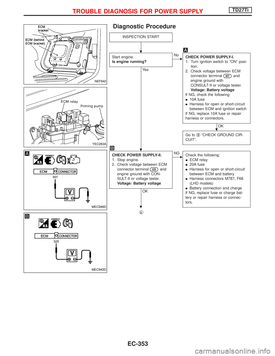
Diagnostic Procedure
INSPECTION START
Start engine.
Is engine running?
Ye s
ENo
CHECK POWER SUPPLY-I.
1. Turn ignition switch to ªONº posi-
tion.
2. Check voltage between ECM
connector terminal
507and
engine ground with
CONSULT-II or voltage tester.
Voltage: Battery voltage
If NG, check the following:
I10A fuse
IHarness for open or short-circuit
between ECM and ignition switch
If NG, replace 10A fuse or repair
harness or connectors.
OK
Go toq
BªCHECK GROUND CIR-
CUITº.
CHECK POWER SUPPLY-II.
1. Stop engine.
2. Check voltage between ECM
connector terminal
325and
engine ground with CON-
SULT-II or voltage tester.
Voltage: Battery voltage
OK
ENG
Check the following:
IECM relay
I20A fuse
IHarness for open or short-circuit
between ECM and battery
IHarness connectors M787, F66
(LHD models)
IBattery connection and charge
If NG, replace fuse or charge bat-
tery or repair harness or connec-
tors.
qA
NEF642
YEC283A
MEC946D
MEC943D
H
H
H
H
TROUBLE DIAGNOSIS FOR POWER SUPPLYTD27Ti
EC-353
Page 722 of 1767
qA
Disconnect and reconnect harness
connectors, then retest.
Trouble is not fixed.
Check ECM pin terminals for damage or
the connection of ECM harness connector.
Reconnect ECM harness connector and
retest.
INSPECTION END
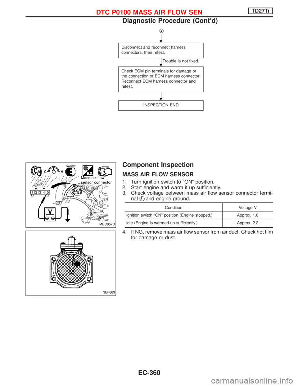
Component Inspection
MASS AIR FLOW SENSOR
1. Turn ignition switch to ªONº position.
2. Start engine and warm it up sufficiently.
3. Check voltage between mass air flow sensor connector termi-
nalq
5and engine ground.
Condition Voltage V
Ignition switch ªONº position (Engine stopped.) Approx. 1.0
Idle (Engine is warmed-up sufficiently.) Approx. 2.2
4. If NG, remove mass air flow sensor from air duct. Check hot film
for damage or dust.
MEC957D
NEF669
H
H
H
DTC P0100 MASS AIR FLOW SENTD27Ti
Diagnostic Procedure (Cont'd)
EC-360