2002 NISSAN TERRANO air condition
[x] Cancel search: air conditionPage 818 of 1767
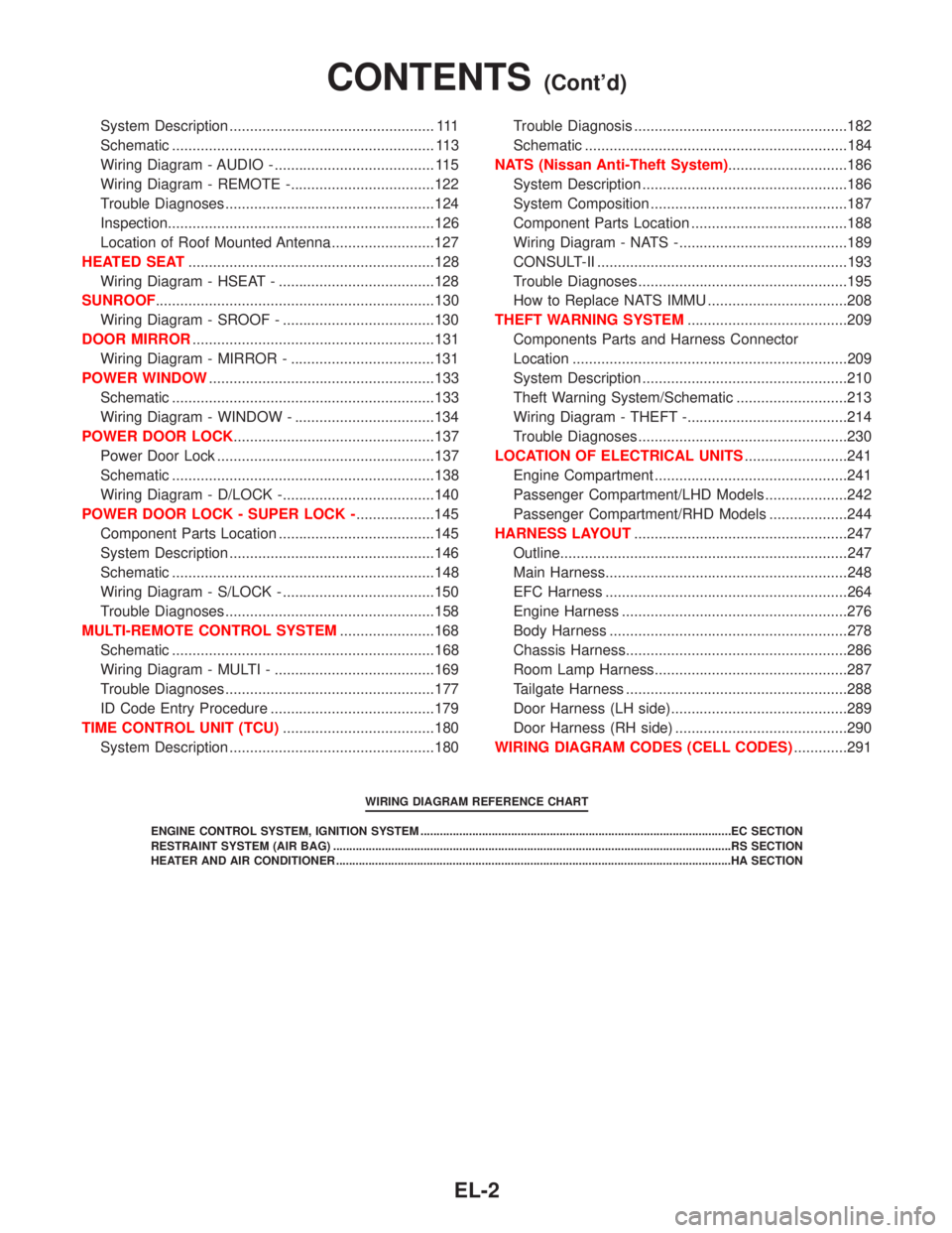
System Description .................................................. 111
Schematic ................................................................ 113
Wiring Diagram - AUDIO - ....................................... 115
Wiring Diagram - REMOTE -...................................122
Trouble Diagnoses...................................................124
Inspection.................................................................126
Location of Roof Mounted Antenna .........................127
HEATED SEAT............................................................128
Wiring Diagram - HSEAT - ......................................128
SUNROOF....................................................................130
Wiring Diagram - SROOF - .....................................130
DOOR MIRROR...........................................................131
Wiring Diagram - MIRROR - ...................................131
POWER WINDOW.......................................................133
Schematic ................................................................133
Wiring Diagram - WINDOW - ..................................134
POWER DOOR LOCK.................................................137
Power Door Lock .....................................................137
Schematic ................................................................138
Wiring Diagram - D/LOCK -.....................................140
POWER DOOR LOCK - SUPER LOCK -...................145
Component Parts Location ......................................145
System Description ..................................................146
Schematic ................................................................148
Wiring Diagram - S/LOCK - .....................................150
Trouble Diagnoses...................................................158
MULTI-REMOTE CONTROL SYSTEM.......................168
Schematic ................................................................168
Wiring Diagram - MULTI - .......................................169
Trouble Diagnoses...................................................177
ID Code Entry Procedure ........................................179
TIME CONTROL UNIT (TCU).....................................180
System Description ..................................................180Trouble Diagnosis ....................................................182
Schematic ................................................................184
NATS (Nissan Anti-Theft System).............................186
System Description ..................................................186
System Composition ................................................187
Component Parts Location ......................................188
Wiring Diagram - NATS -.........................................189
CONSULT-II .............................................................193
Trouble Diagnoses...................................................195
How to Replace NATS IMMU ..................................208
THEFT WARNING SYSTEM.......................................209
Components Parts and Harness Connector
Location ...................................................................209
System Description ..................................................210
Theft Warning System/Schematic ...........................213
Wiring Diagram - THEFT -.......................................214
Trouble Diagnoses...................................................230
LOCATION OF ELECTRICAL UNITS.........................241
Engine Compartment ...............................................241
Passenger Compartment/LHD Models ....................242
Passenger Compartment/RHD Models ...................244
HARNESS LAYOUT....................................................247
Outline......................................................................247
Main Harness...........................................................248
EFC Harness ...........................................................264
Engine Harness .......................................................276
Body Harness ..........................................................278
Chassis Harness......................................................286
Room Lamp Harness...............................................287
Tailgate Harness ......................................................288
Door Harness (LH side)...........................................289
Door Harness (RH side) ..........................................290
WIRING DIAGRAM CODES (CELL CODES).............291
WIRING DIAGRAM REFERENCE CHART
ENGINE CONTROL SYSTEM, IGNITION SYSTEM ................................................................................................EC SECTION
RESTRAINT SYSTEM (AIR BAG) ...........................................................................................................................RS SECTION
HEATER AND AIR CONDITIONER ..........................................................................................................................HA SECTION
CONTENTS(Cont'd)
EL-2
Page 858 of 1767
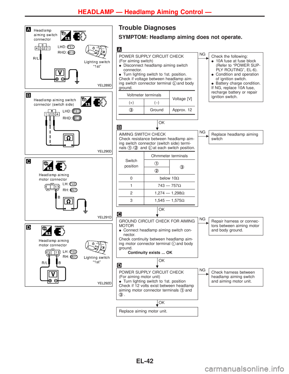
Trouble Diagnoses
SYMPTOM: Headlamp aiming does not operate.
POWER SUPPLY CIRCUIT CHECK
(For aiming switch)
IDisconnect headlamp aiming switch
connector.
ITurn lighting switch to 1st. position.
Check if voltage between headlamp aim-
ing switch connector terminalq
3and body
ground.
OK
ENG
Check the following:
I10A fuse at fuse block
(Refer to ªPOWER SUP-
PLY ROUTINGº, EL-6).
ICondition and operation
of ignition switch.
IBattery charge condition.
If NG, replace 10A fuse,
recharge battery or repair
ignition switch.
AIMING SWITCH CHECK
Check resistance between headlamp aim-
ing switch connector (switch side) termi-
nalsq
1/q2andq3at each switch position.
OK
ENG
Replace headlamp aiming
switch
GROUND CIRCUIT CHECK FOR AIMING
MOTOR
IConnect headlamp aiming switch con-
nector.
Check continuity between headlamp aim-
ing motor connector terminalq
1and body
ground.
Continuity exists ... OK
OK
ENG
Repair harness or connec-
tors between aiming motor
and body ground.
POWER SUPPLY CIRCUIT CHECK
(For aiming motor unit)
ITurn lighting switch to 1st. position
Check if 12 volts exist between headlamp
aiming motor connector terminalsq
1and
q3.
OK
ENG
Check harness between
headlamp aiming switch
and aiming motor unit.
Replace aiming motor unit.
Voltmeter terminals
Voltage [V]
(+) (þ)
q
3Ground Approx. 12
Switch
positionOhmmeter terminals
q1q3q2
0 below 10W
1 743 Ð 757W
2 1,274 Ð 1,298W
3 1,545 Ð 1,575W
YEL289D
YEL290D
YEL291D
YEL292D
H
H
H
H
HEADLAMP Ð Headlamp Aiming Control Ð
EL-42
Page 893 of 1767
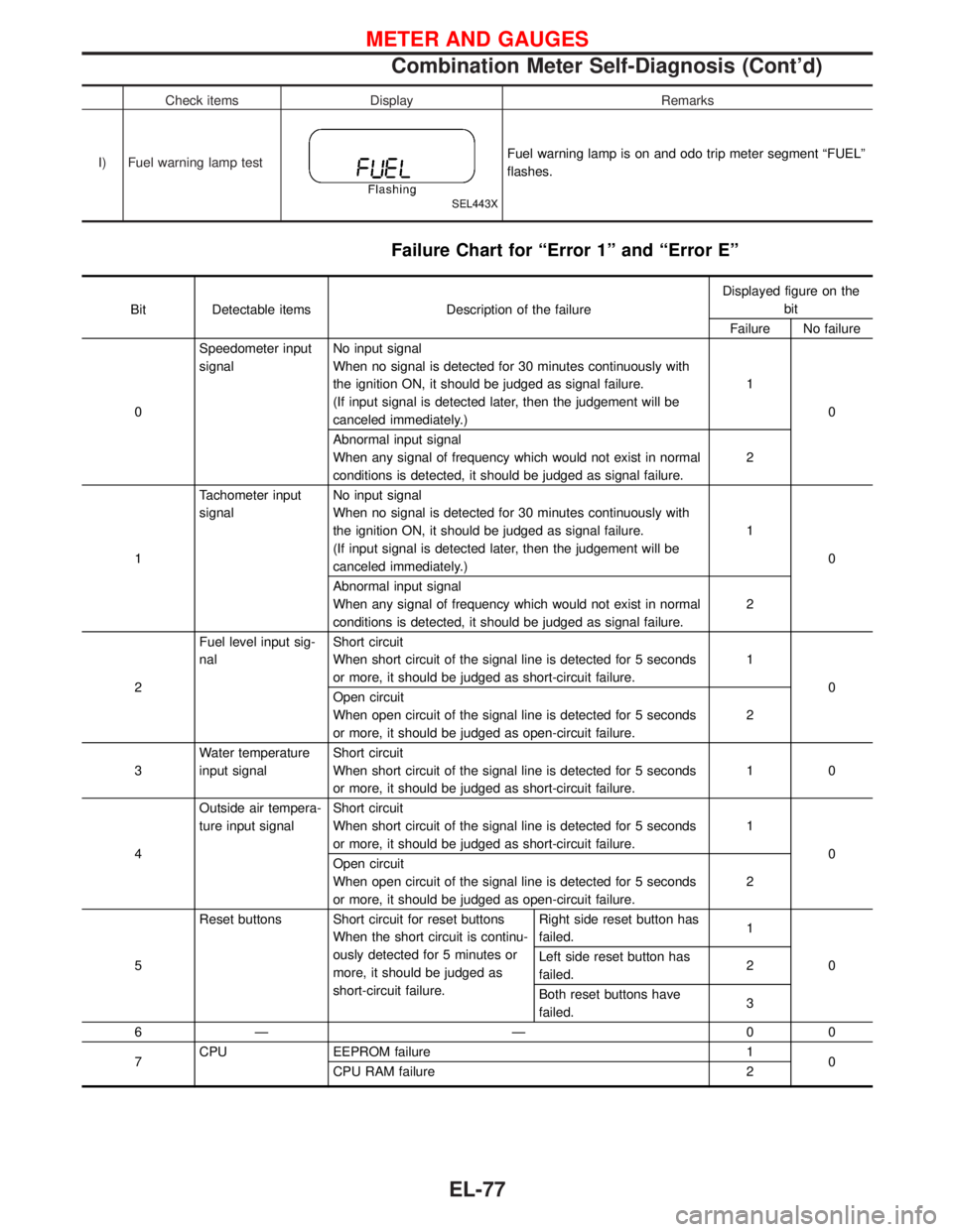
Check items Display Remarks
I) Fuel warning lamp test
SEL443X
Fuel warning lamp is on and odo trip meter segment ªFUELº
flashes.
Failure Chart for ªError 1º and ªError Eº
Bit Detectable items Description of the failureDisplayed figure on the
bit
Failure No failure
0Speedometer input
signalNo input signal
When no signal is detected for 30 minutes continuously with
the ignition ON, it should be judged as signal failure.
(If input signal is detected later, then the judgement will be
canceled immediately.)1
0
Abnormal input signal
When any signal of frequency which would not exist in normal
conditions is detected, it should be judged as signal failure.2
1Tachometer input
signalNo input signal
When no signal is detected for 30 minutes continuously with
the ignition ON, it should be judged as signal failure.
(If input signal is detected later, then the judgement will be
canceled immediately.)1
0
Abnormal input signal
When any signal of frequency which would not exist in normal
conditions is detected, it should be judged as signal failure.2
2Fuel level input sig-
nalShort circuit
When short circuit of the signal line is detected for 5 seconds
or more, it should be judged as short-circuit failure.1
0
Open circuit
When open circuit of the signal line is detected for 5 seconds
or more, it should be judged as open-circuit failure.2
3Water temperature
input signalShort circuit
When short circuit of the signal line is detected for 5 seconds
or more, it should be judged as short-circuit failure.10
4Outside air tempera-
ture input signalShort circuit
When short circuit of the signal line is detected for 5 seconds
or more, it should be judged as short-circuit failure.1
0
Open circuit
When open circuit of the signal line is detected for 5 seconds
or more, it should be judged as open-circuit failure.2
5Reset buttons Short circuit for reset buttons
When the short circuit is continu-
ously detected for 5 minutes or
more, it should be judged as
short-circuit failure.Right side reset button has
failed.1
0 Left side reset button has
failed.2
Both reset buttons have
failed.3
6Ð Ð 00
7CPU EEPROM failure 1
0
CPU RAM failure 2
METER AND GAUGES
Combination Meter Self-Diagnosis (Cont'd)
EL-77
Page 941 of 1767
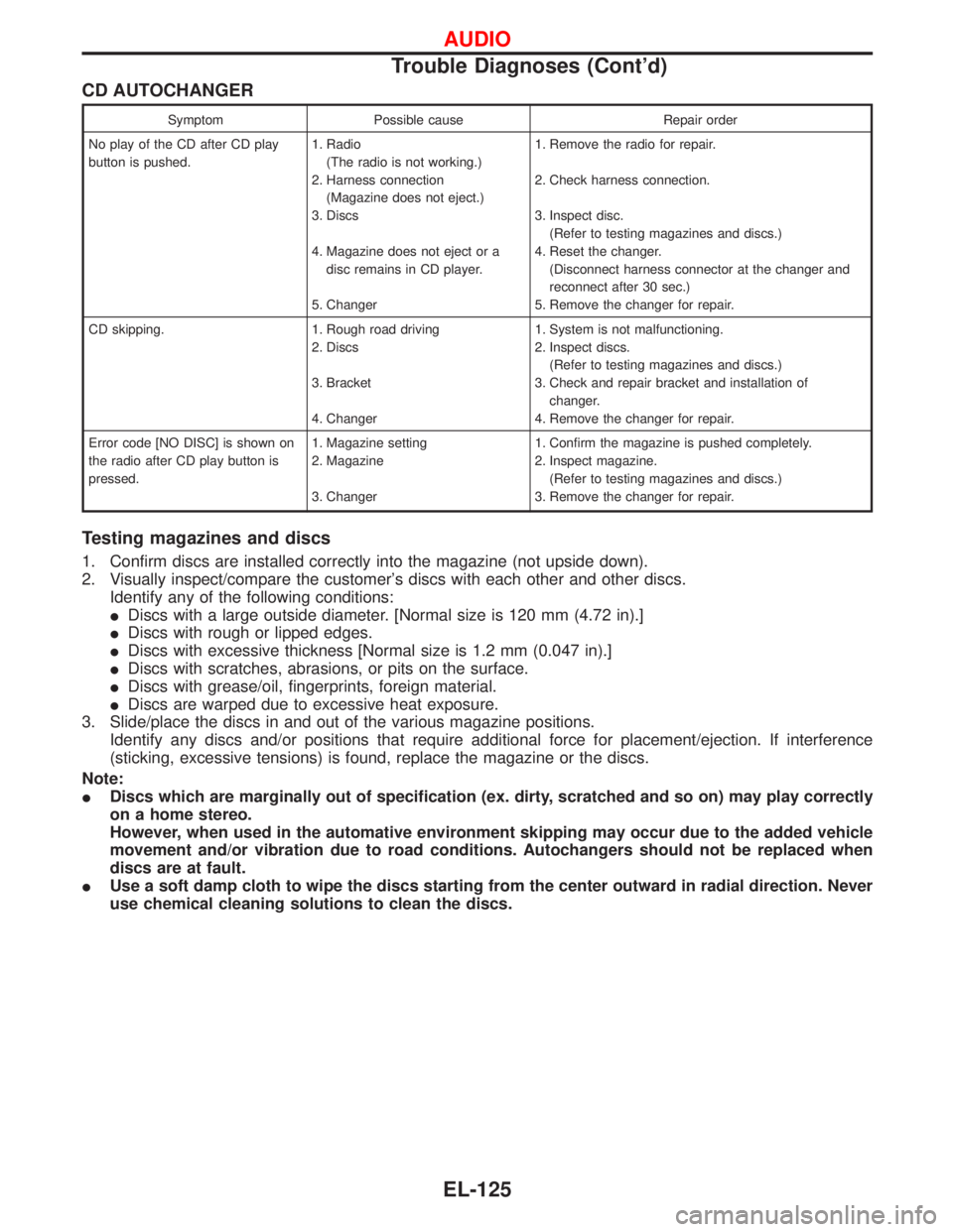
CD AUTOCHANGER
Symptom Possible cause Repair order
No play of the CD after CD play
button is pushed.1. Radio
(The radio is not working.)
2. Harness connection
(Magazine does not eject.)
3. Discs
4. Magazine does not eject or a
disc remains in CD player.
5. Changer1. Remove the radio for repair.
2. Check harness connection.
3. Inspect disc.
(Refer to testing magazines and discs.)
4. Reset the changer.
(Disconnect harness connector at the changer and
reconnect after 30 sec.)
5. Remove the changer for repair.
CD skipping. 1. Rough road driving
2. Discs
3. Bracket
4. Changer1. System is not malfunctioning.
2. Inspect discs.
(Refer to testing magazines and discs.)
3. Check and repair bracket and installation of
changer.
4. Remove the changer for repair.
Error code [NO DISC] is shown on
the radio after CD play button is
pressed.1. Magazine setting
2. Magazine
3. Changer1. Confirm the magazine is pushed completely.
2. Inspect magazine.
(Refer to testing magazines and discs.)
3. Remove the changer for repair.
Testing magazines and discs
1. Confirm discs are installed correctly into the magazine (not upside down).
2. Visually inspect/compare the customer's discs with each other and other discs.
Identify any of the following conditions:
IDiscs with a large outside diameter. [Normal size is 120 mm (4.72 in).]
IDiscs with rough or lipped edges.
IDiscs with excessive thickness [Normal size is 1.2 mm (0.047 in).]
IDiscs with scratches, abrasions, or pits on the surface.
IDiscs with grease/oil, fingerprints, foreign material.
IDiscs are warped due to excessive heat exposure.
3. Slide/place the discs in and out of the various magazine positions.
Identify any discs and/or positions that require additional force for placement/ejection. If interference
(sticking, excessive tensions) is found, replace the magazine or the discs.
Note:
IDiscs which are marginally out of specification (ex. dirty, scratched and so on) may play correctly
on a home stereo.
However, when used in the automative environment skipping may occur due to the added vehicle
movement and/or vibration due to road conditions. Autochangers should not be replaced when
discs are at fault.
IUse a soft damp cloth to wipe the discs starting from the center outward in radial direction. Never
use chemical cleaning solutions to clean the discs.
AUDIO
Trouble Diagnoses (Cont'd)
EL-125
Page 982 of 1767
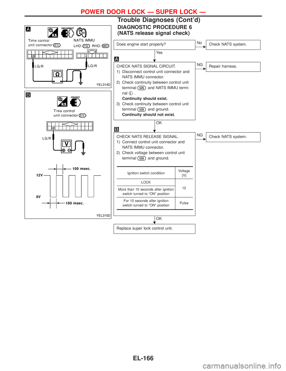
DIAGNOSTIC PROCEDURE 6
(NATS release signal check)
Does engine start properly?
Ye s
ENo
Check NATS system.
CHECK NATS SIGNAL CIRCUIT.
1) Disconnect control unit connector and
NATS IMMU connector.
2) Check continuity between control unit
terminal
U26and NATS IMMU termi-
nalq
3.
Continuity should exist.
3) Check continuity between control unit
terminal
U26and ground.
Continuity should not exist.
OK
ENG
Repair harness.
CHECK NATS RELEASE SIGNAL.
1) Connect control unit connector and
NATS IMMU connector.
2) Check voltage between control unit
terminal
U26and ground.
OK
ENG
Check NATS system.
Replace super lock control unit.
Ignition switch conditionVoltage
[V]
LOCK
12
More than 10 seconds after ignition
switch turned to ªONº position
For 10 seconds after ignition
switch turned to ªONº positionPulse
YEL314D
YEL315D
H
H
H
POWER DOOR LOCK Ð SUPER LOCK Ð
Trouble Diagnoses (Cont'd)
EL-166
Page 1107 of 1767
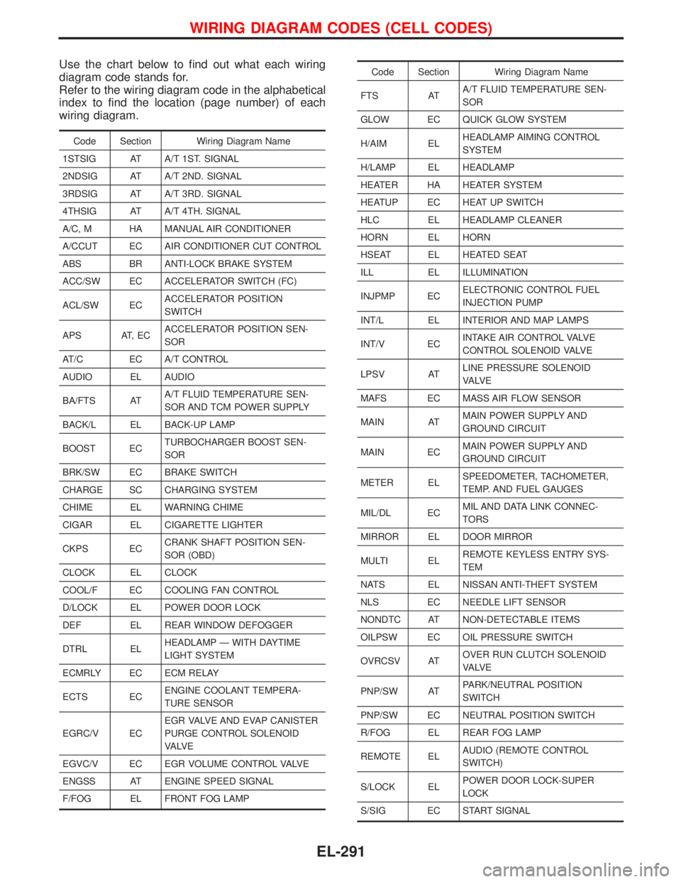
Use the chart below to find out what each wiring
diagram code stands for.
Refer to the wiring diagram code in the alphabetical
index to find the location (page number) of each
wiring diagram.
Code Section Wiring Diagram Name
1STSIG AT A/T 1ST. SIGNAL
2NDSIG AT A/T 2ND. SIGNAL
3RDSIG AT A/T 3RD. SIGNAL
4THSIG AT A/T 4TH. SIGNAL
A/C, M HA MANUAL AIR CONDITIONER
A/CCUT EC AIR CONDITIONER CUT CONTROL
ABS BR ANTI-LOCK BRAKE SYSTEM
ACC/SW EC ACCELERATOR SWITCH (FC)
ACL/SW ECACCELERATOR POSITION
SWITCH
APS AT, ECACCELERATOR POSITION SEN-
SOR
AT/C EC A/T CONTROL
AUDIO EL AUDIO
BA/FTS ATA/T FLUID TEMPERATURE SEN-
SOR AND TCM POWER SUPPLY
BACK/L EL BACK-UP LAMP
BOOST ECTURBOCHARGER BOOST SEN-
SOR
BRK/SW EC BRAKE SWITCH
CHARGE SC CHARGING SYSTEM
CHIME EL WARNING CHIME
CIGAR EL CIGARETTE LIGHTER
CKPS ECCRANK SHAFT POSITION SEN-
SOR (OBD)
CLOCK EL CLOCK
COOL/F EC COOLING FAN CONTROL
D/LOCK EL POWER DOOR LOCK
DEF EL REAR WINDOW DEFOGGER
DTRL ELHEADLAMP Ð WITH DAYTIME
LIGHT SYSTEM
ECMRLY EC ECM RELAY
ECTS ECENGINE COOLANT TEMPERA-
TURE SENSOR
EGRC/V ECEGR VALVE AND EVAP CANISTER
PURGE CONTROL SOLENOID
VA LV E
EGVC/V EC EGR VOLUME CONTROL VALVE
ENGSS AT ENGINE SPEED SIGNAL
F/FOG EL FRONT FOG LAMP
Code Section Wiring Diagram Name
FTS ATA/T FLUID TEMPERATURE SEN-
SOR
GLOW EC QUICK GLOW SYSTEM
H/AIM ELHEADLAMP AIMING CONTROL
SYSTEM
H/LAMP EL HEADLAMP
HEATER HA HEATER SYSTEM
HEATUP EC HEAT UP SWITCH
HLC EL HEADLAMP CLEANER
HORN EL HORN
HSEAT EL HEATED SEAT
ILL EL ILLUMINATION
INJPMP ECELECTRONIC CONTROL FUEL
INJECTION PUMP
INT/L EL INTERIOR AND MAP LAMPS
INT/V ECINTAKE AIR CONTROL VALVE
CONTROL SOLENOID VALVE
LPSV ATLINE PRESSURE SOLENOID
VA LV E
MAFS EC MASS AIR FLOW SENSOR
MAIN ATMAIN POWER SUPPLY AND
GROUND CIRCUIT
MAIN ECMAIN POWER SUPPLY AND
GROUND CIRCUIT
METER ELSPEEDOMETER, TACHOMETER,
TEMP. AND FUEL GAUGES
MIL/DL ECMIL AND DATA LINK CONNEC-
TORS
MIRROR EL DOOR MIRROR
MULTI ELREMOTE KEYLESS ENTRY SYS-
TEM
NATS EL NISSAN ANTI-THEFT SYSTEM
NLS EC NEEDLE LIFT SENSOR
NONDTC AT NON-DETECTABLE ITEMS
OILPSW EC OIL PRESSURE SWITCH
OVRCSV ATOVER RUN CLUTCH SOLENOID
VA LV E
PNP/SW ATPARK/NEUTRAL POSITION
SWITCH
PNP/SW EC NEUTRAL POSITION SWITCH
R/FOG EL REAR FOG LAMP
REMOTE ELAUDIO (REMOTE CONTROL
SWITCH)
S/LOCK ELPOWER DOOR LOCK-SUPER
LOCK
S/SIG EC START SIGNAL
WIRING DIAGRAM CODES (CELL CODES)
EL-291
Page 1117 of 1767
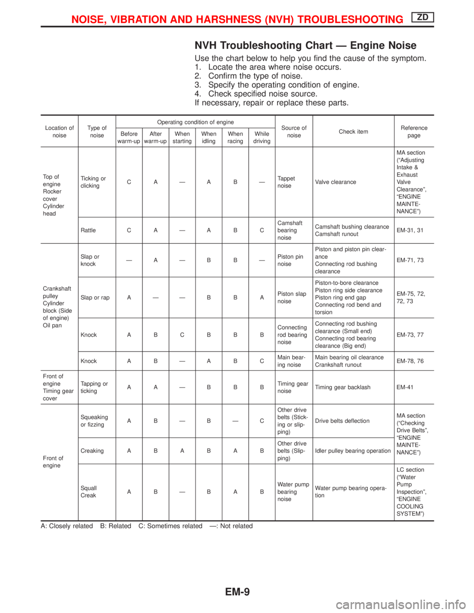
NVH Troubleshooting Chart Ð Engine Noise
Use the chart below to help you find the cause of the symptom.
1. Locate the area where noise occurs.
2. Confirm the type of noise.
3. Specify the operating condition of engine.
4. Check specified noise source.
If necessary, repair or replace these parts.
Location of
noiseType of
noiseOperating condition of engine
Source of
noiseCheck itemReference
page Before
warm-upAfter
warm-upWhen
startingWhen
idlingWhen
racingWhile
driving
To p o f
engine
Rocker
cover
Cylinder
headTicking or
clickingC AÐA BÐTappet
noiseValve clearanceMA section
(ªAdjusting
Intake &
Exhaust
Valve
Clearanceº,
ªENGINE
MAINTE-
NANCEº)
Rattle C A Ð A B CCamshaft
bearing
noiseCamshaft bushing clearance
Camshaft runoutEM-31, 31
Crankshaft
pulley
Cylinder
block (Side
of engine)
Oil panSlap or
knockÐAÐB BÐPiston pin
noisePiston and piston pin clear-
ance
Connecting rod bushing
clearanceEM-71, 73
Slap or rap A Ð Ð B B APiston slap
noisePiston-to-bore clearance
Piston ring side clearance
Piston ring end gap
Connecting rod bend and
torsionEM-75, 72,
72, 73
Knock A B C B B BConnecting
rod bearing
noiseConnecting rod bushing
clearance (Small end)
Connecting rod bearing
clearance (Big end)EM-73, 77
Knock A B Ð A B CMain bear-
ing noiseMain bearing oil clearance
Crankshaft runoutEM-78, 76
Front of
engine
Timing gear
coverTapping or
tickingAAÐBBBTiming gear
noiseTiming gear backlash EM-41
Front of
engineSqueaking
or fizzingA BÐBÐCOther drive
belts (Stick-
ing or slip-
ping)Drive belts deflectionMA section
(ªChecking
Drive Beltsº,
ªENGINE
MAINTE-
NANCEº) CreakingABABABOther drive
belts (Slip-
ping)Idler pulley bearing operation
Squall
CreakABÐBABWater pump
bearing
noiseWater pump bearing opera-
tionLC section
(ªWater
Pump
Inspectionº,
ªENGINE
COOLING
SYSTEMº)
A: Closely related B: Related C: Sometimes related Ð: Not related
NOISE, VIBRATION AND HARSHNESS (NVH) TROUBLESHOOTINGZD
EM-9
Page 1147 of 1767
Removal
1. Remove the engine assembly.
Refer to ªENGINE REMOVALº, EM-63.
2. Place the engine on an engine stand (SST).
Refer to ªCYLINDER BLOCKº, EM-67.
3. Remove the following.
IAuto tensioner bracket
IAir conditioner bracket
IAlternator bracket
IOil tube
IVacuum pump
IRocker cover
IOil pan (upper, lower)
IInjection tube
ISpill tube
IHigh pressure nozzle assembly
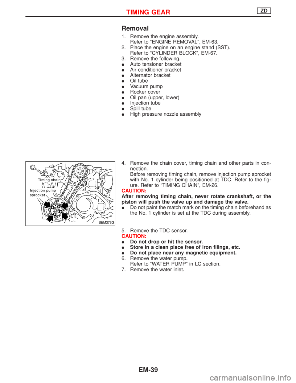
4. Remove the chain cover, timing chain and other parts in con-
nection.
Before removing timing chain, remove injection pump sprocket
with No. 1 cylinder being positioned at TDC. Refer to the fig-
ure. Refer to ªTIMING CHAINº, EM-26.
CAUTION:
After removing timing chain, never rotate crankshaft, or the
piston will push the valve up and damage the valve.
IDo not paint the match mark on the timing chain beforehand as
the No. 1 cylinder is set at the TDC during assembly.
5. Remove the TDC sensor.
CAUTION:
IDo not drop or hit the sensor.
IStore in a clean place free of iron filings, etc.
IDo not place near any magnetic equipment.
6. Remove the water pump.
Refer to ªWATER PUMPº in LC section.
7. Remove the water inlet.
SEM376G
TIMING GEARZD
EM-39