2002 NISSAN TERRANO air condition
[x] Cancel search: air conditionPage 1172 of 1767
Engine room (Left)
3. Remove air duct and air cleaner case.
4. Disconnect vacuum hose to the vehicle on the engine.
5. Disconnect harness connectors from alternator and air com-
pressor.
6. Remove alternator.
7. After removing refrigerant, remove pipes of air compressor and
inlet/outlet.
8. Disconnect heating hose, install blank cap to hose to prevent
coolant from leaking.
9. Remove heating pipe.
10. Remove heat insulator.
11. Remove catalytic converter.
Engine room (Right)
12. Remove power steering reservoir tank from bracket, and fix it
to the vehicle with a rope.
CAUTION:
Keep the reservoir tank level when fixing to prevent oil leak.
13. Remove fuel feed and return hoses.
CAUTION:
Install blank caps immediately to avoid fuel leakage.
14. Remove all harness connectors on the engine, and move har-
nesses to the side of the vehicle.
Vehicle underfloor
15. Remove starter motor.
16. Detach A/T oil cooler pipes from oil pan. (A/T model)
17. Remove rear propeller shaft.
18. Remove mounting bolts to secure the engine to transmission.
1) Remove torque converter installation bolt. (A/T model)
2) Lift transmission bottom with transmission jack, and remove
rear mount members from the vehicle.
3) Lower transmission with the jack, and remove upper mounting
bolts securing the engine to transmission.
4) Lift transmission with the jack, and reinstall rear mount mem-
bers to the vehicle.
5) Position the jack to the front side of transmission.
6) Remove remaining mounting bolts securing the engine to trans-
mission.
Removal operation
19. Remove air conditioner high pressure pipes at the rear of the
engine room.
IThis is due to some inconvenience in the rear slinger installa-
tion.
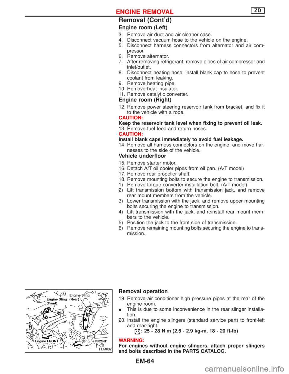
20. Install the engine slingers (standard service part) to front-left
and rear-right.
:25-28N×m (2.5 - 2.9 kg-m, 18 - 20 ft-lb)
WARNING:
For engines without engine slingers, attach proper slingers
and bolts described in the PARTS CATALOG.
FEM082
ENGINE REMOVALZD
Removal (Cont'd)
EM-64
Page 1208 of 1767
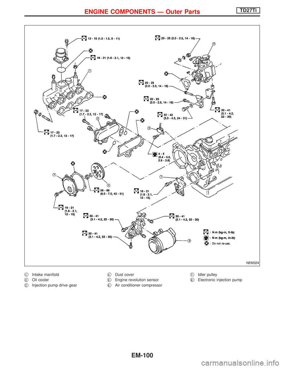
q1Intake manifold
q
2Oil cooler
q
3Injection pump drive gearq
4Dust cover
q
5Engine revolution sensor
q
6Air conditioner compressorq
7Idler pulley
q
8Electronic injection pump
NEM324
ENGINE COMPONENTS Ð Outer PartsTD27Ti
EM-100
Page 1227 of 1767
Removal and Installation
Turbocharger should not be disassembled.
1. Drain engine coolant.
2. Remove the following:
IAir duct and intercooler components
IHeat shield plates
IExhaust front tube
IOil tubes
IWater tubes
3. Remove turbocharger from exhaust manifold.
4. Remove turbocharger bracket bolts.
Inspection
Condition 1: Low engine power
Probable cause Corrective action
Air leak at the connection of compressor housing and suc-
tion hose/inlet tube, or inlet and intake manifold.
ECorrect the connection.
Exhaust gas leak at the connection of turbine housing and
exhaust manifold, connecting tube or exhaust outlet.
ECorrect the connection or replace gasket.
By-pass valve is stuck in open position.E
Replace turbocharger assembly.
Stuck or worn journal or bearing.E
Broken shaft.E
Sludge on back of turbine wheel.E
Broken turbine wheel.E
Condition 2: Excessively high engine power
Probable cause Corrective action
Disconnected or cracked rubber hose of by-pass valve
controller.
ECorrect or replace rubber hose.
By-pass valve is stuck in closed position.E
Replace turbocharger assembly.
Controller diaphragm is broken.E
TURBOCHARGERTD27Ti
EM-119
Page 1272 of 1767
Removal and Installation
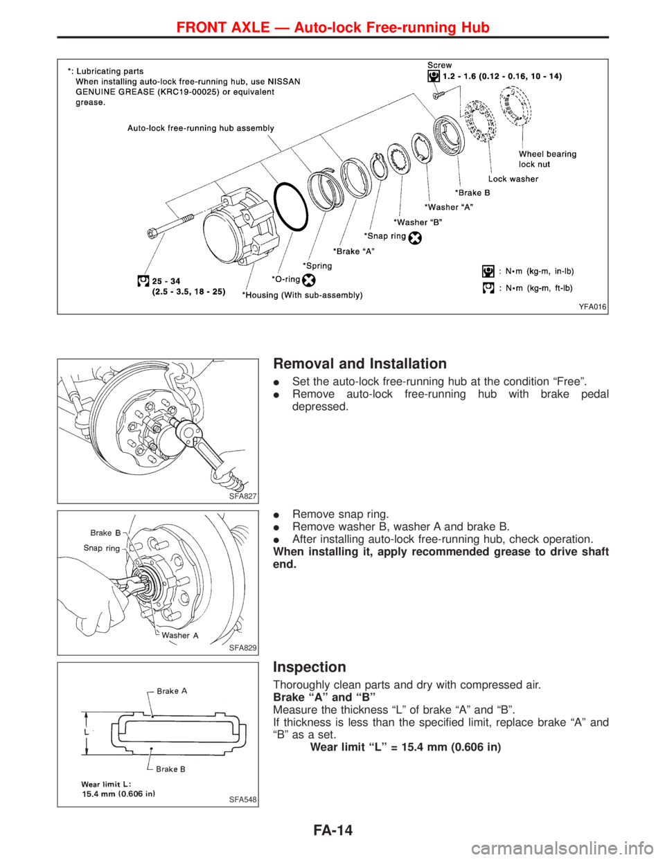
ISet the auto-lock free-running hub at the condition ªFreeº.
IRemove auto-lock free-running hub with brake pedal
depressed.
IRemove snap ring.
IRemove washer B, washer A and brake B.
IAfter installing auto-lock free-running hub, check operation.
When installing it, apply recommended grease to drive shaft
end.
Inspection
Thoroughly clean parts and dry with compressed air.
Brake ªAº and ªBº
Measure the thickness ªLº of brake ªAº and ªBº.
If thickness is less than the specified limit, replace brake ªAº and
ªBº as a set.
Wear limit ªLº = 15.4 mm (0.606 in)
YFA016
SFA827
SFA829
SFA548
FRONT AXLE Ð Auto-lock Free-running Hub
FA-14
Page 1324 of 1767
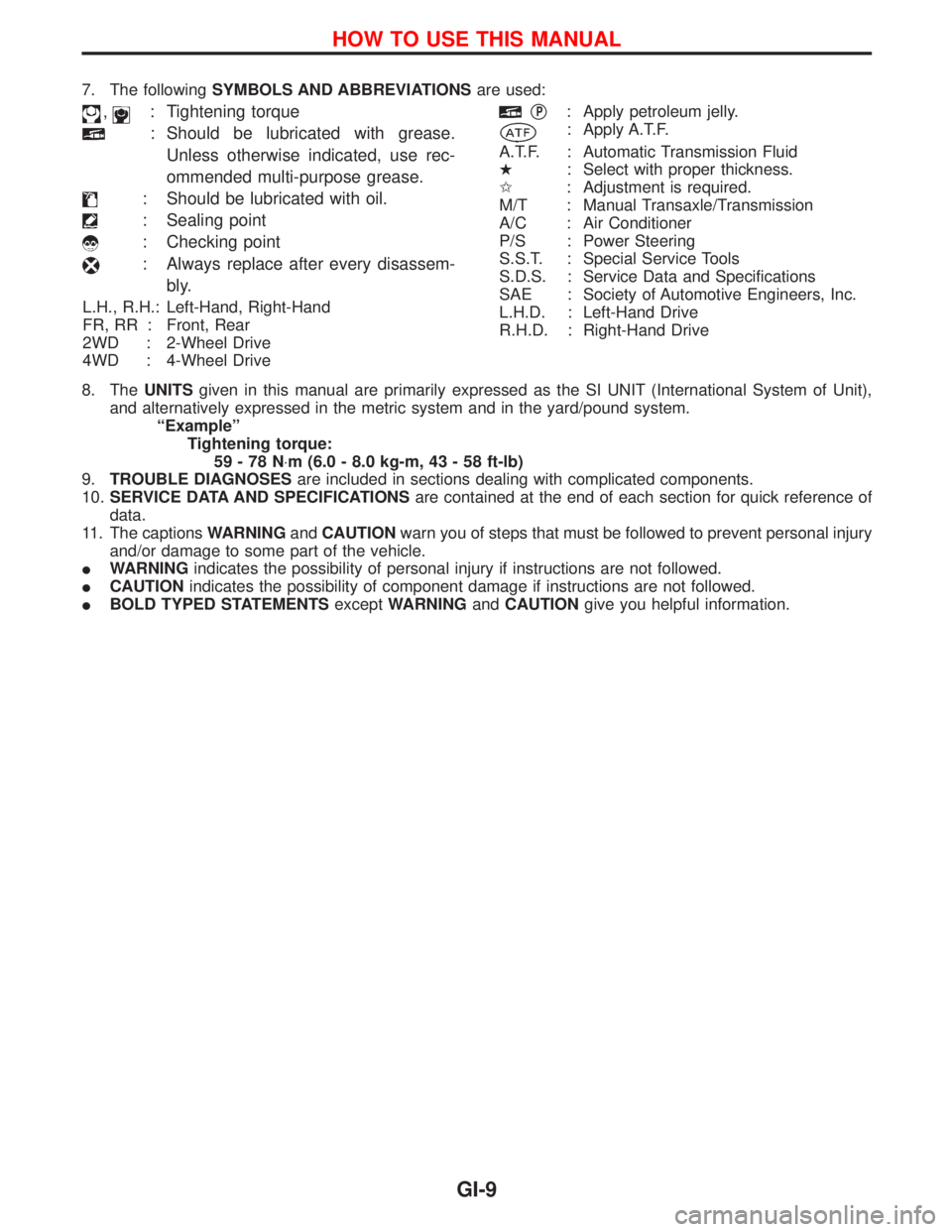
7. The followingSYMBOLS AND ABBREVIATIONSare used:
,: Tightening torque
: Should be lubricated with grease.
Unless otherwise indicated, use rec-
ommended multi-purpose grease.
: Should be lubricated with oil.
: Sealing point
: Checking point
: Always replace after every disassem-
bly.
L.H., R.H.: Left-Hand, Right-Hand
FR, RR : Front, Rear
2WD : 2-Wheel Drive
4WD : 4-Wheel Drive
qP: Apply petroleum jelly.
: Apply A.T.F.
A.T.F. : Automatic Transmission Fluid
H: Select with proper thickness.
I: Adjustment is required.
M/T : Manual Transaxle/Transmission
A/C : Air Conditioner
P/S : Power Steering
S.S.T. : Special Service Tools
S.D.S. : Service Data and Specifications
SAE : Society of Automotive Engineers, Inc.
L.H.D. : Left-Hand Drive
R.H.D. : Right-Hand Drive
8. TheUNITSgiven in this manual are primarily expressed as the SI UNIT (International System of Unit),
and alternatively expressed in the metric system and in the yard/pound system.
ªExampleº
Tightening torque:
59-78N×m (6.0 - 8.0 kg-m, 43 - 58 ft-lb)
9.TROUBLE DIAGNOSESare included in sections dealing with complicated components.
10.SERVICE DATA AND SPECIFICATIONSare contained at the end of each section for quick reference of
data.
11. The captionsWARNINGandCAUTIONwarn you of steps that must be followed to prevent personal injury
and/or damage to some part of the vehicle.
IWARNINGindicates the possibility of personal injury if instructions are not followed.
ICAUTIONindicates the possibility of component damage if instructions are not followed.
IBOLD TYPED STATEMENTSexceptWARNINGandCAUTIONgive you helpful information.
HOW TO USE THIS MANUAL
GI-9
Page 1337 of 1767
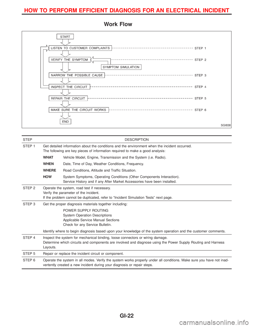
Work Flow
STEP DESCRIPTION
STEP 1 Get detailed information about the conditions and the environment when the incident occurred.
The following are key pieces of information required to make a good analysis:
WHATVehicle Model, Engine, Transmission and the System (i.e. Radio).
WHENDate, Time of Day, Weather Conditions, Frequency.
WHERERoad Conditions, Altitude and Traffic Situation.
HOWSystem Symptoms, Operating Conditions (Other Components Interaction).
Service History and if any After Market Accessories have been installed.
STEP 2 Operate the system, road test if necessary.
Verify the parameter of the incident.
If the problem cannot be duplicated, refer to ªIncident Simulation Testsº next page.
STEP 3 Get the proper diagnosis materials together including:
POWER SUPPLY ROUTING
System Operation Descriptions
Applicable Service Manual Sections
Check for any Service Bulletin.
Identify where to begin diagnosis based upon your knowledge of the system operation and the customer comments.
STEP 4 Inspect the system for mechanical binding, loose connectors or wiring damage.
Determine which circuits and components are involved and diagnose using the Power Supply Routing and Harness
Layouts.
STEP 5 Repair or replace the incident circuit or component.
STEP 6 Operate the system in all modes. Verify the system works properly under all conditions. Make sure you have not inad-
vertently created a new incident during your diagnosis or repair steps.
SGI838
HOW TO PERFORM EFFICIENT DIAGNOSIS FOR AN ELECTRICAL INCIDENT
GI-22
Page 1354 of 1767
HEATER & AIR CONDITIONER
SECTION
HA
CONTENTS
PRECAUTIONS...............................................................2
Introduction ..................................................................2
Identification .................................................................2
Precautions for Working with HFC-134a (R-134a) .....3
General Refrigerant Precautions .................................3
Precautions for Refrigerant Connection ......................4
Precautions for Servicing Compressor ........................5
DESCRIPTION - Overall System...................................6
Control Operation ........................................................6
Component Layout ......................................................7
Air Flow ........................................................................8
DESCRIPTION - Refrigeration System.........................9
Refrigeration Cycle ......................................................9
PREPARATION..............................................................10
Special Service Tools ................................................10
HFC-134a (R-134a) Service Tools and
Equipment .................................................................. 11
Precautions for Service Equipment ...........................13
SERVICE PROCEDURES.............................................15
HFC-134a (R-134a) Service Procedure ....................15
Refrigerant Lines .......................................................17
Compressor Mounting ...............................................21
Belt Tension ...............................................................21
LUBRICATION OIL - Checking and Adjusting...........22
Lubrication Oil ............................................................22Maintenance of Oil Quantity in Compressor .............22
Checking and Adjusting .............................................22
COMPRESSOR - Model DKV-14C (ZEXEL make)......24
Compressor Clutch ....................................................24
DIAGNOSES - Overall System....................................27
How to Perform Trouble Diagnoses for Quick
and Accurate Repair ..................................................27
Operation Check ........................................................28
Performance Chart ....................................................30
Performance Test Diagnoses ....................................31
TROUBLE DIAGNOSES...............................................36
Symptom Chart ..........................................................36
Preliminary Check......................................................37
Harness Layout for A/C System ................................39
Wiring Diagram - Heater............................................41
Wiring Diagram ..........................................................43
Main Power Supply and Ground Circuit Check ........51
Diagnostic Procedure 1 .............................................52
Diagnostic Procedure 2 .............................................54
Diagnostic Procedure 3 .............................................59
Electrical Components Inspection .............................60
Control Linkage Adjustment.......................................61
SERVICE DATA AND SPECIFICATIONS (SDS)..........64
General Specifications ...............................................64
Inspection and Adjustment ........................................64
When you read wiring diagrams:
IRead GI section, ªHOW TO READ WIRING DIAGRAMSº.
ISee EL section, ªPOWER SUPPLY ROUTINGº for power distribution circuit.
When you perform trouble diagnoses, read GI section, ªHOW TO FOLLOW FLOW CHART IN
TROUBLE DIAGNOSESº.
Page 1355 of 1767
Introduction
To prevent the ozone layer from being destroyed, the HFC-134a (R-134a) refrigerant has replaced the previ-
ously used CFC-12 (R-12).
The new and previous service tools, refrigerant, lubricant, etc. are not interchangeable due to differences in
their physical properties and characteristics.
Always service the HFC-134a (R-134a) air conditioning system using the specified tools, lubricant and
refrigerant, observing the following precautions:
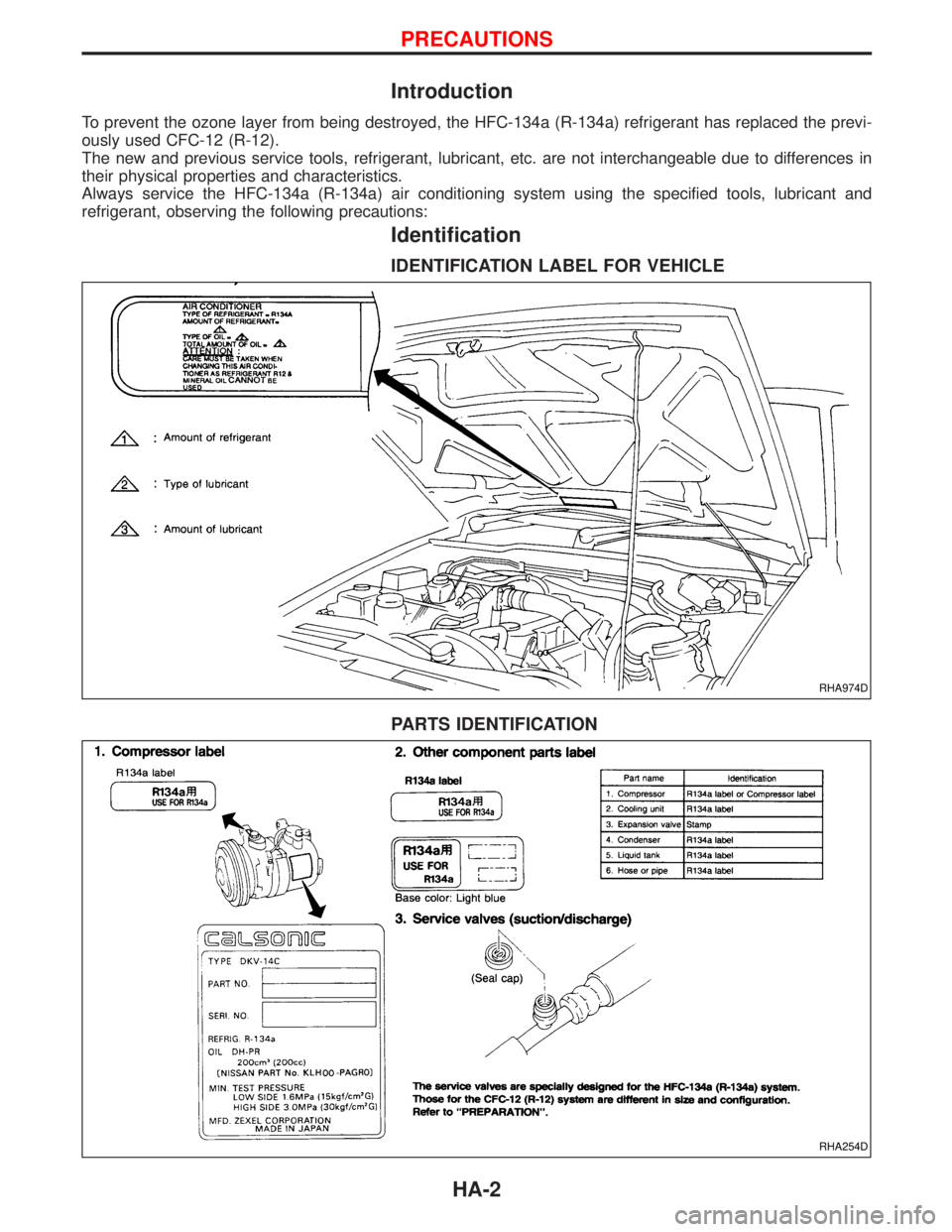
Identification
IDENTIFICATION LABEL FOR VEHICLE
PARTS IDENTIFICATION
RHA974D
RHA254D
PRECAUTIONS
HA-2