2002 NISSAN TERRANO air condition
[x] Cancel search: air conditionPage 655 of 1767
Alphabetical & Numerical Index for DTC
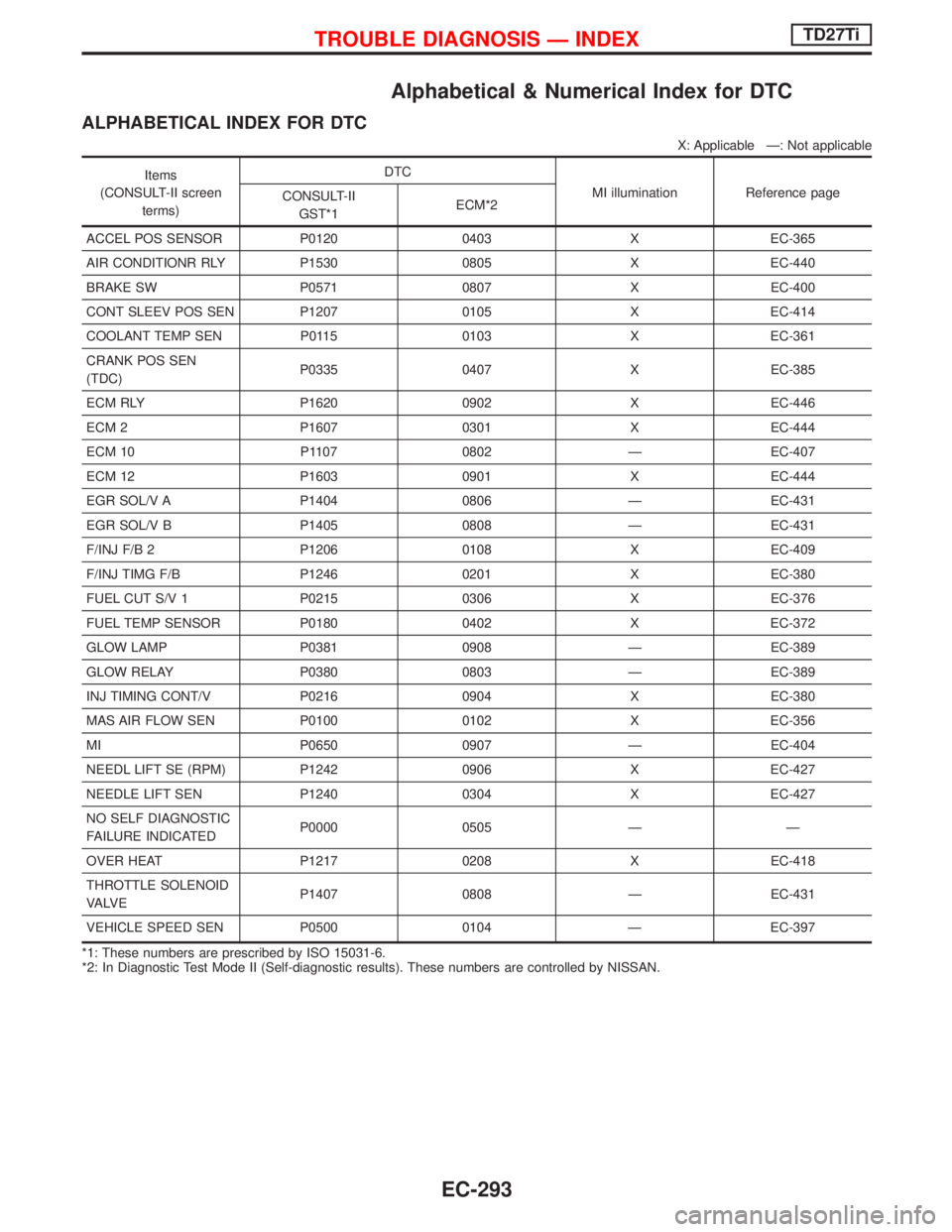
ALPHABETICAL INDEX FOR DTC
X: Applicable Ð: Not applicable
Items
(CONSULT-II screen
terms)DTC
MI illumination Reference page
CONSULT-II
GST*1ECM*2
ACCEL POS SENSOR P0120 0403 X EC-365
AIR CONDITIONR RLY P1530 0805 X EC-440
BRAKE SW P0571 0807 X EC-400
CONT SLEEV POS SEN P1207 0105 X EC-414
COOLANT TEMP SEN P0115 0103 X EC-361
CRANK POS SEN
(TDC)P0335 0407 X EC-385
ECM RLY P1620 0902 X EC-446
ECM 2 P1607 0301 X EC-444
ECM 10 P1107 0802 Ð EC-407
ECM 12 P1603 0901 X EC-444
EGR SOL/V A P1404 0806 Ð EC-431
EGR SOL/V B P1405 0808 Ð EC-431
F/INJ F/B 2 P1206 0108 X EC-409
F/INJ TIMG F/B P1246 0201 X EC-380
FUEL CUT S/V 1 P0215 0306 X EC-376
FUEL TEMP SENSOR P0180 0402 X EC-372
GLOW LAMP P0381 0908 Ð EC-389
GLOW RELAY P0380 0803 Ð EC-389
INJ TIMING CONT/V P0216 0904 X EC-380
MAS AIR FLOW SEN P0100 0102 X EC-356
MI P0650 0907 Ð EC-404
NEEDL LIFT SE (RPM) P1242 0906 X EC-427
NEEDLE LIFT SEN P1240 0304 X EC-427
NO SELF DIAGNOSTIC
FAILURE INDICATEDP0000 0505 Ð Ð
OVER HEAT P1217 0208 X EC-418
THROTTLE SOLENOID
VA LV EP1407 0808 Ð EC-431
VEHICLE SPEED SEN P0500 0104 Ð EC-397
*1: These numbers are prescribed by ISO 15031-6.
*2: In Diagnostic Test Mode II (Self-diagnostic results). These numbers are controlled by NISSAN.
TROUBLE DIAGNOSIS Ð INDEXTD27Ti
EC-293
Page 656 of 1767
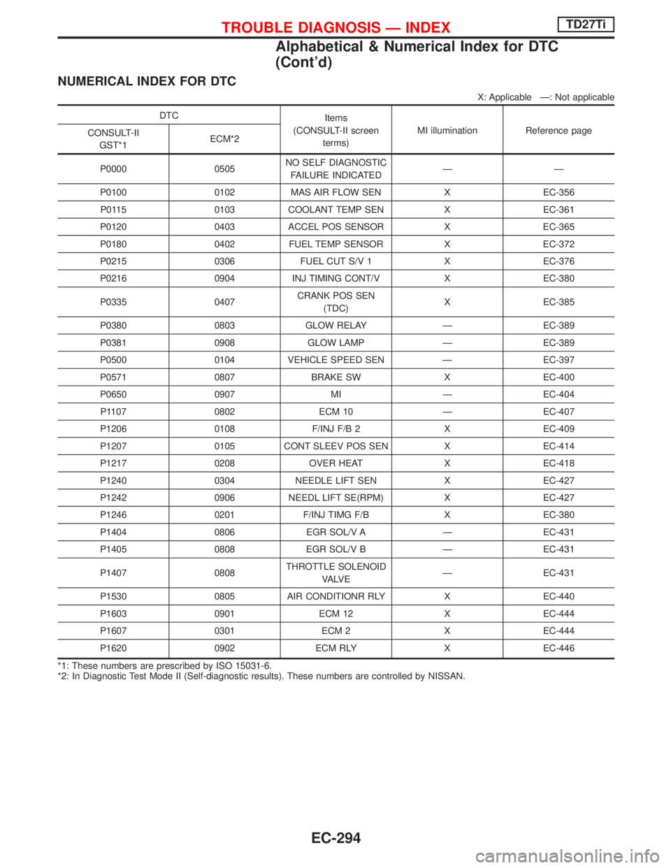
NUMERICAL INDEX FOR DTC
X: Applicable Ð: Not applicable
DTC
Items
(CONSULT-II screen
terms)MI illumination Reference page
CONSULT-II
GST*1ECM*2
P0000 0505NO SELF DIAGNOSTIC
FAILURE INDICATEDÐÐ
P0100 0102 MAS AIR FLOW SEN X EC-356
P0115 0103 COOLANT TEMP SEN X EC-361
P0120 0403 ACCEL POS SENSOR X EC-365
P0180 0402 FUEL TEMP SENSOR X EC-372
P0215 0306 FUEL CUT S/V 1 X EC-376
P0216 0904 INJ TIMING CONT/V X EC-380
P0335 0407CRANK POS SEN
(TDC)X EC-385
P0380 0803 GLOW RELAY Ð EC-389
P0381 0908 GLOW LAMP Ð EC-389
P0500 0104 VEHICLE SPEED SEN Ð EC-397
P0571 0807 BRAKE SW X EC-400
P0650 0907 MI Ð EC-404
P1107 0802 ECM 10 Ð EC-407
P1206 0108 F/INJ F/B 2 X EC-409
P1207 0105 CONT SLEEV POS SEN X EC-414
P1217 0208 OVER HEAT X EC-418
P1240 0304 NEEDLE LIFT SEN X EC-427
P1242 0906 NEEDL LIFT SE(RPM) X EC-427
P1246 0201 F/INJ TIMG F/B X EC-380
P1404 0806 EGR SOL/V A Ð EC-431
P1405 0808 EGR SOL/V B Ð EC-431
P1407 0808THROTTLE SOLENOID
VA LV EÐ EC-431
P1530 0805 AIR CONDITIONR RLY X EC-440
P1603 0901 ECM 12 X EC-444
P1607 0301 ECM 2 X EC-444
P1620 0902 ECM RLY X EC-446
*1: These numbers are prescribed by ISO 15031-6.
*2: In Diagnostic Test Mode II (Self-diagnostic results). These numbers are controlled by NISSAN.
TROUBLE DIAGNOSIS Ð INDEXTD27Ti
Alphabetical & Numerical Index for DTC
(Cont'd)
EC-294
Page 667 of 1767
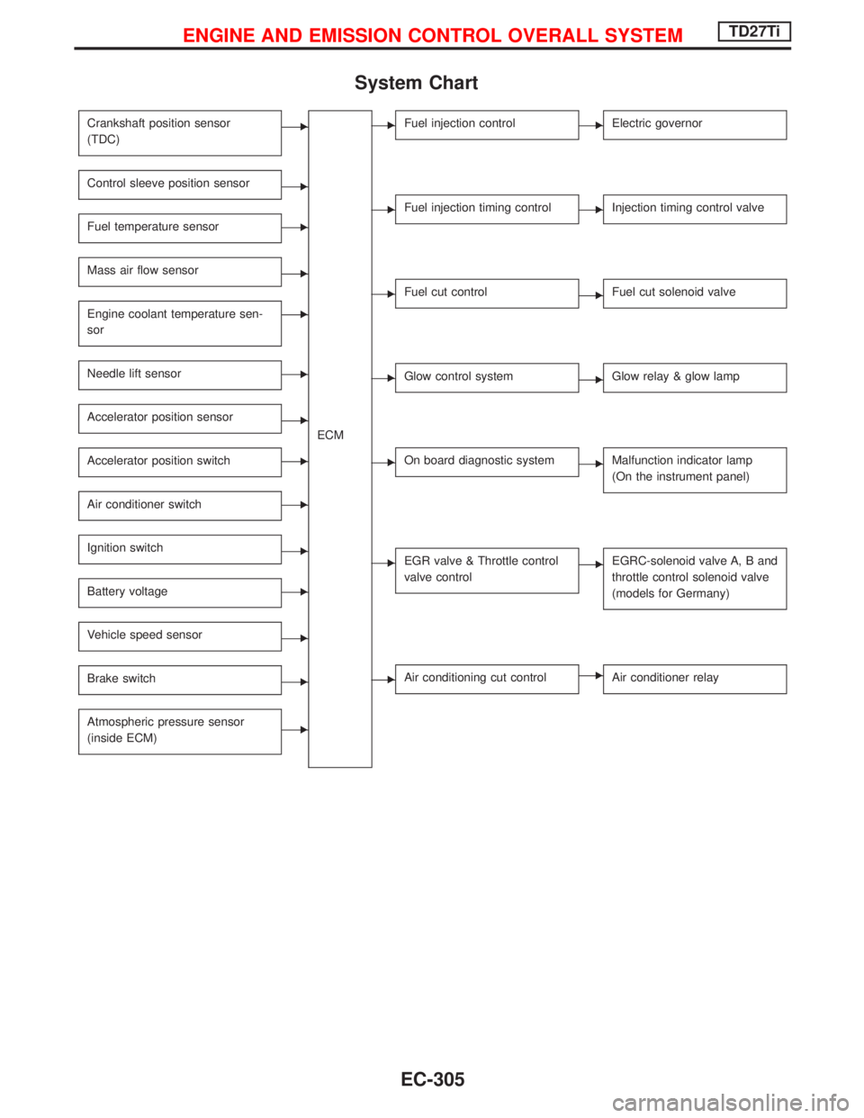
System Chart
Crankshaft position sensor
(TDC)E
ECM
Control sleeve position sensorE
Fuel temperature sensorE
Mass air flow sensorE
Engine coolant temperature sen-
sorE
Needle lift sensorE
Accelerator position sensorE
Accelerator position switchE
Air conditioner switchE
Ignition switchE
Battery voltageE
Vehicle speed sensorE
Brake switchE
Atmospheric pressure sensor
(inside ECM)E
EFuel injection controlEElectric governor
EFuel injection timing controlEInjection timing control valve
EFuel cut controlEFuel cut solenoid valve
EGlow control systemEGlow relay & glow lamp
EOn board diagnostic systemEMalfunction indicator lamp
(On the instrument panel)
EEGR valve & Throttle control
valve controlEEGRC-solenoid valve A, B and
throttle control solenoid valve
(models for Germany)
EAir conditioning cut controlEAir conditioner relay
ENGINE AND EMISSION CONTROL OVERALL SYSTEMTD27Ti
EC-305
Page 669 of 1767
IDLE CONTROL
Input/output signal line
Engine coolant temperature sensorEEngine coolant temperature
ECM
EElectric
governor
Crankshaft position sensor (TDC)EEngine speed
Air conditioner switch
EAir Conditioner operation
Control sleeve position sensor
EControl sleeve position
Accelerator position switch
EIdle position
Vehicle speed sensor
EVehicle speed
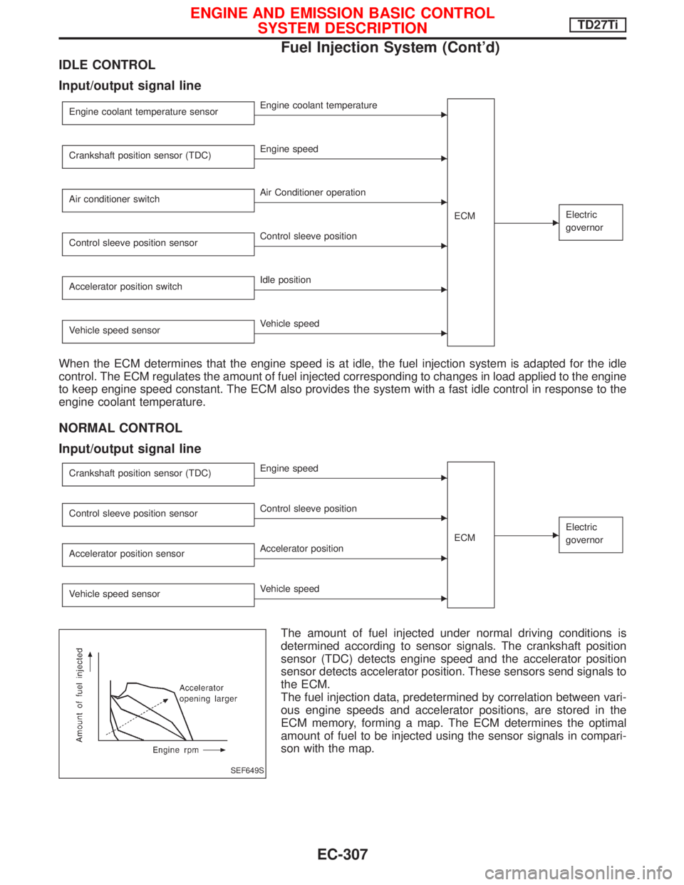
When the ECM determines that the engine speed is at idle, the fuel injection system is adapted for the idle
control. The ECM regulates the amount of fuel injected corresponding to changes in load applied to the engine
to keep engine speed constant. The ECM also provides the system with a fast idle control in response to the
engine coolant temperature.
NORMAL CONTROL
Input/output signal line
Crankshaft position sensor (TDC)EEngine speed
ECM
EElectric
governor
Control sleeve position sensorEControl sleeve position
Accelerator position sensor
EAccelerator position
Vehicle speed sensor
EVehicle speed
The amount of fuel injected under normal driving conditions is
determined according to sensor signals. The crankshaft position
sensor (TDC) detects engine speed and the accelerator position
sensor detects accelerator position. These sensors send signals to
the ECM.
The fuel injection data, predetermined by correlation between vari-
ous engine speeds and accelerator positions, are stored in the
ECM memory, forming a map. The ECM determines the optimal
amount of fuel to be injected using the sensor signals in compari-
son with the map.
SEF649S
ENGINE AND EMISSION BASIC CONTROL
SYSTEM DESCRIPTIONTD27Ti
Fuel Injection System (Cont'd)
EC-307
Page 673 of 1767
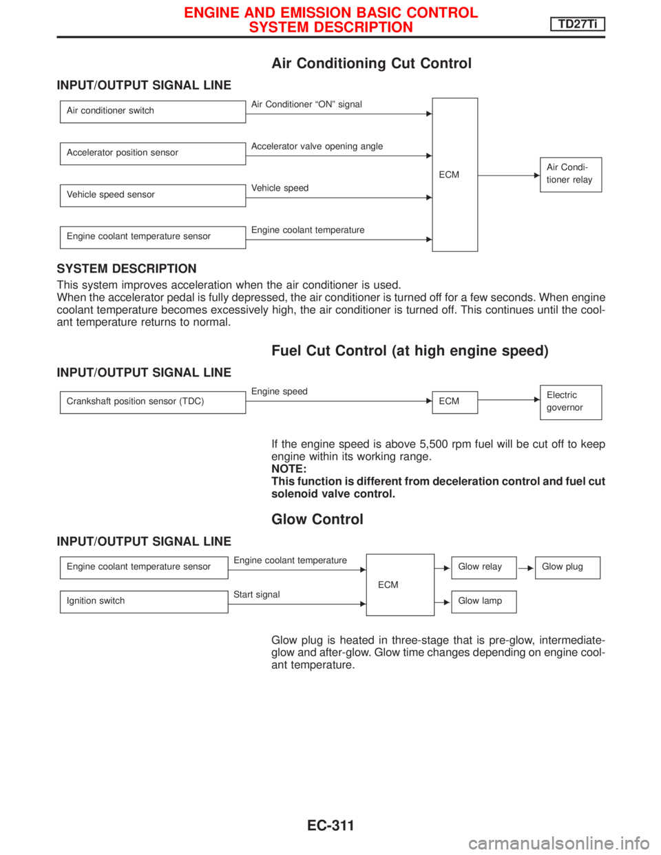
Air Conditioning Cut Control
INPUT/OUTPUT SIGNAL LINE
Air conditioner switchEAir Conditioner ªONº signal
ECM
EAir Condi-
tioner relay
Accelerator position sensorEAccelerator valve opening angle
Vehicle speed sensor
EVehicle speed
Engine coolant temperature sensor
EEngine coolant temperature
SYSTEM DESCRIPTION
This system improves acceleration when the air conditioner is used.
When the accelerator pedal is fully depressed, the air conditioner is turned off for a few seconds. When engine
coolant temperature becomes excessively high, the air conditioner is turned off. This continues until the cool-
ant temperature returns to normal.
Fuel Cut Control (at high engine speed)
INPUT/OUTPUT SIGNAL LINE
Crankshaft position sensor (TDC)EEngine speed
ECMEElectric
governor
If the engine speed is above 5,500 rpm fuel will be cut off to keep
engine within its working range.
NOTE:
This function is different from deceleration control and fuel cut
solenoid valve control.
Glow Control
INPUT/OUTPUT SIGNAL LINE
Engine coolant temperature sensorEEngine coolant temperature
ECMEGlow relayEGlow plug
Ignition switchEStart signalEGlow lamp
Glow plug is heated in three-stage that is pre-glow, intermediate-
glow and after-glow. Glow time changes depending on engine cool-
ant temperature.
ENGINE AND EMISSION BASIC CONTROL
SYSTEM DESCRIPTIONTD27Ti
EC-311
Page 684 of 1767
How to Erase DTC (Without CONSULT-II)
1. If the ignition switch stays ªONº after repair work, be sure to turn ignition switch ªOFFº once. Wait at least
5 seconds and then turn it ªONº (engine stopped) again.
2. Change the diagnostic test mode from Mode II to Mode I by using the data link connector. (See EC-323.)
The emission related diagnostic information in the ECM can be erased by changing the diagnostic test mode.
IIf the battery is disconnected, the emission-related diagnostic information will be lost after approx.
24 hours.
IErasing the emission-related diagnostic information using CONSULT-II is easier and quicker than
switching the diagnostic test mode using the data link connector.
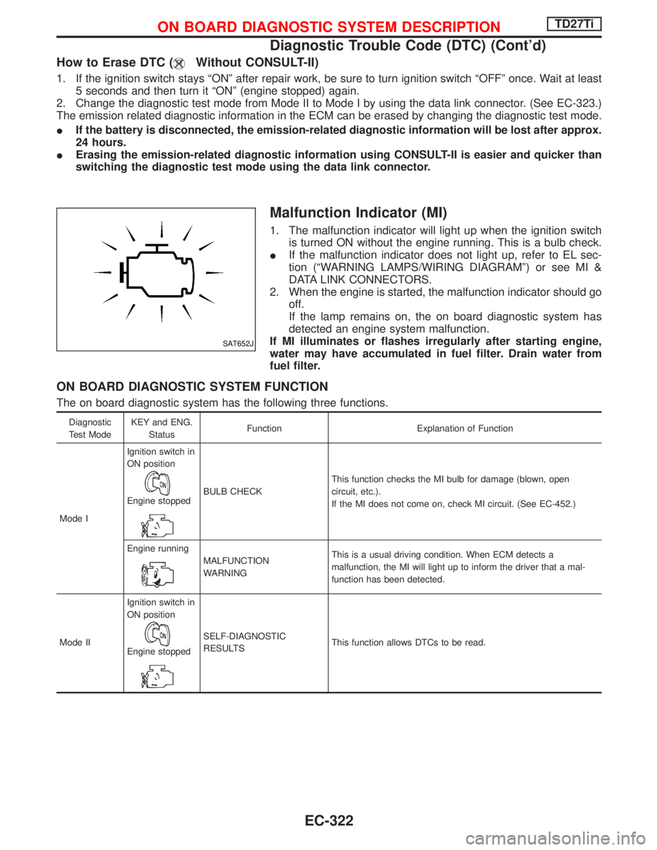
Malfunction Indicator (MI)
1. The malfunction indicator will light up when the ignition switch
is turned ON without the engine running. This is a bulb check.
IIf the malfunction indicator does not light up, refer to EL sec-
tion (ªWARNING LAMPS/WIRING DIAGRAMº) or see MI &
DATA LINK CONNECTORS.
2. When the engine is started, the malfunction indicator should go
off.
If the lamp remains on, the on board diagnostic system has
detected an engine system malfunction.
If MI illuminates or flashes irregularly after starting engine,
water may have accumulated in fuel filter. Drain water from
fuel filter.
ON BOARD DIAGNOSTIC SYSTEM FUNCTION
The on board diagnostic system has the following three functions.
Diagnostic
Test ModeKEY and ENG.
StatusFunction Explanation of Function
Mode IIgnition switch in
ON position
Engine stoppedBULB CHECKThis function checks the MI bulb for damage (blown, open
circuit, etc.).
If the MI does not come on, check MI circuit. (See EC-452.)
Engine running
MALFUNCTION
WARNINGThis is a usual driving condition. When ECM detects a
malfunction, the MI will light up to inform the driver that a mal-
function has been detected.
Mode IIIgnition switch in
ON position
Engine stopped
SELF-DIAGNOSTIC
RESULTSThis function allows DTCs to be read.
SAT652J
ON BOARD DIAGNOSTIC SYSTEM DESCRIPTIONTD27Ti
Diagnostic Trouble Code (DTC) (Cont'd)
EC-322
Page 690 of 1767
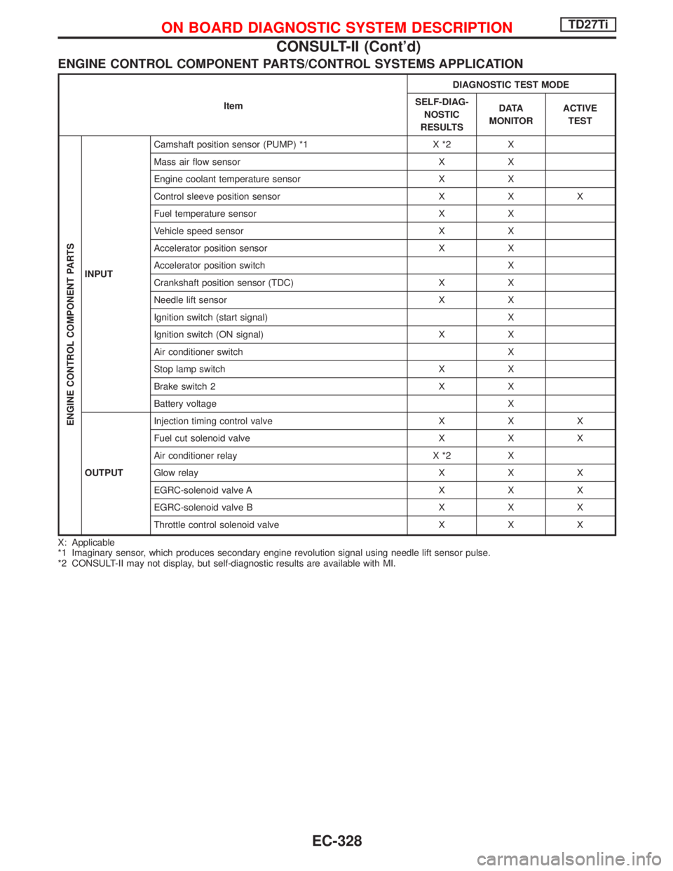
ENGINE CONTROL COMPONENT PARTS/CONTROL SYSTEMS APPLICATION
ItemDIAGNOSTIC TEST MODE
SELF-DIAG-
NOSTIC
RESULTSD ATA
MONITORACTIVE
TEST
ENGINE CONTROL COMPONENT PARTS
INPUTCamshaft position sensor (PUMP) *1 X *2 X
Mass air flow sensor X X
Engine coolant temperature sensor X X
Control sleeve position sensor X X X
Fuel temperature sensor X X
Vehicle speed sensor X X
Accelerator position sensor X X
Accelerator position switch X
Crankshaft position sensor (TDC) X X
Needle lift sensor X X
Ignition switch (start signal) X
Ignition switch (ON signal) X X
Air conditioner switch X
Stop lamp switch X X
Brake switch 2 X X
Battery voltage X
OUTPUTInjection timing control valve X X X
Fuel cut solenoid valve X X X
Air conditioner relay X *2 X
Glow relay X X X
EGRC-solenoid valve A X X X
EGRC-solenoid valve B X X X
Throttle control solenoid valve X X X
X: Applicable
*1 Imaginary sensor, which produces secondary engine revolution signal using needle lift sensor pulse.
*2 CONSULT-II may not display, but self-diagnostic results are available with MI.
ON BOARD DIAGNOSTIC SYSTEM DESCRIPTIONTD27Ti
CONSULT-II (Cont'd)
EC-328
Page 691 of 1767
![NISSAN TERRANO 2002 Service Repair Manual SELF-DIAGNOSTIC MODE
Regarding items detected in ªSELF-DIAG RESULTSº mode, refer to ªTROUBLE DIAGNOSIS Ð INDEXº,
EC-293.
DATA MONITOR MODE
Monitored item
[Unit]ECM
input
signalsMain
signalsDescri](/manual-img/5/57393/w960_57393-690.png "NISSAN TERRANO 2002 Service Repair Manual SELF-DIAGNOSTIC MODE
Regarding items detected in ªSELF-DIAG RESULTSº mode, refer to ªTROUBLE DIAGNOSIS Ð INDEXº,
EC-293.
DATA MONITOR MODE
Monitored item
[Unit]ECM
input
signalsMain
signalsDescri")
SELF-DIAGNOSTIC MODE
Regarding items detected in ªSELF-DIAG RESULTSº mode, refer to ªTROUBLE DIAGNOSIS Ð INDEXº,
EC-293.
DATA MONITOR MODE
Monitored item
[Unit]ECM
input
signalsMain
signalsDescription Remarks
CKPS×RPM
(TDC) [rpm]
qq
IThe engine speed computed from the
crankshaft position sensor (TDC) signal
is displayed.
CMPS×RPM -
PUMP [rpm]
qqIThe engine speed computed from the
needle lift sensor signal is displayed.
COOLAN TEMP/S
[ÉC] or [ÉF]
qq
IThe engine coolant temperature (deter-
mined by the signal voltage of the engine
coolant temperature sensor) is displayed.IWhen the engine coolant temperature
sensor is open or short-circuited, ECM
enters fail-safe mode. The same data as
the fuel temperature is displayed.
VHCL SPEED SE
[km/h] or [mph]
qqIThe vehicle speed computed from the
vehicle speed sensor signal is displayed.
FUEL TEMP SEN
[ÉC] or [ÉF]
qq
IThe fuel temperature (determined by the
signal voltage of the fuel temperature
sensor) is displayed.
ACCEL POS SEN [V]
qqIThe accelerator position sensor signal
voltage is displayed.
OFF ACCEL POS
[ON/OFF]
qqIIndicates [ON/OFF] condition from the
accelerator position switch signal.ISignal at approximately 9É opened.
C/SLEEV POS/S [V]
qqIThe control sleeve position sensor signal
voltage is displayed.
BATTERY VOLT [V]
qqIThe power supply voltage of ECM is dis-
played.
START SIGNAL
[ON/OFF]
qqIIndicates [ON/OFF] condition from the
starter signal.IAfter starting the engine, [OFF] is dis-
played regardless of the starter signal.
AIR COND SIG
[ON/OFF]
qq
IIndicates [ON/OFF] condition of the air
conditioner switch as determined by the
air conditioner signal.
BRAKE SW
[ON/OFF]
qIIndicates [ON/OFF] condition of the stop
lamp switch.
BRAKE SW2
[ON/OFF]
qIIndicates [ON/OFF] condition of the
brake switch 2.
IGN SW
[ON/OFF]
qqIIndicates [ON/OFF] condition from igni-
tion switch.
MAS AIR/FL SE [V]
qqIThe signal voltage of the mass air flow
sensor is displayed.IWhen the engine is stopped, a certain
value is indicated.
ACT INJ TIMG [É]
q
IThe actual injection timing angle deter-
mined by the ECM (an approximate aver-
age angle between injection start and
end from TDC) is displayed.
TARGET F/INJ
[mm
3/stroke]qIThe target fuel injection quantity (deter-
mined by the ECM according to the input
signal) is indicated.
NOTE:
Any monitored item that does not match the vehicle being diagnosed is deleted from the display automatically.
ON BOARD DIAGNOSTIC SYSTEM DESCRIPTIONTD27Ti
CONSULT-II (Cont'd)
EC-329