Page 434 of 1767
TER-
MINAL
NO.WIRE
COLORITEM CONDITIONDATA (DC Voltage and Pulse
Signal)
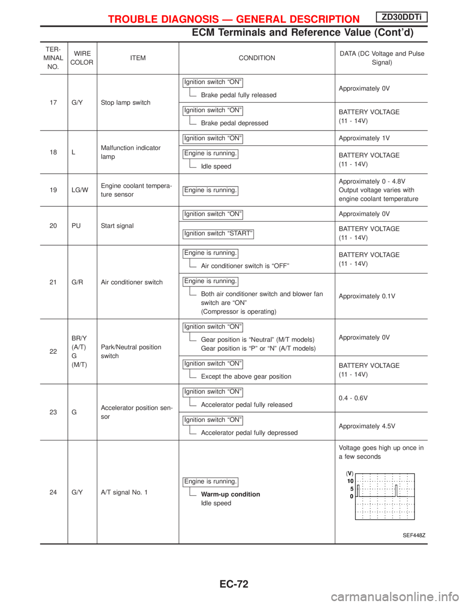
17 G/Y Stop lamp switchIgnition switch ªONº
Brake pedal fully releasedApproximately 0V
Ignition switch ªONº
Brake pedal depressedBATTERY VOLTAGE
(11 - 14V)
18 LMalfunction indicator
lampIgnition switch ªONº
Approximately 1V
Engine is running.
Idle speedBATTERY VOLTAGE
(11 - 14V)
19 LG/WEngine coolant tempera-
ture sensorEngine is running.
Approximately 0 - 4.8V
Output voltage varies with
engine coolant temperature
20 PU Start signalIgnition switch ªONº
Approximately 0V
Ignition switch ªSTARTº
BATTERY VOLTAGE
(11 - 14V)
21 G/R Air conditioner switchEngine is running.
Air conditioner switch is ªOFFºBATTERY VOLTAGE
(11 - 14V)
Engine is running.
Both air conditioner switch and blower fan
switch are ªONº
(Compressor is operating)Approximately 0.1V
22BR/Y
(A/T)
G
(M/T)Park/Neutral position
switchIgnition switch ªONº
Gear position is ªNeutralº (M/T models)
Gear position is ªPº or ªNº (A/T models)Approximately 0V
Ignition switch ªONº
Except the above gear positionBATTERY VOLTAGE
(11 - 14V)
23 GAccelerator position sen-
sorIgnition switch ªONº
Accelerator pedal fully released0.4 - 0.6V
Ignition switch ªONº
Accelerator pedal fully depressedApproximately 4.5V
24 G/Y A/T signal No. 1Engine is running.
Warm-up condition
Idle speedVoltage goes high up once in
a few seconds
SEF448Z
TROUBLE DIAGNOSIS Ð GENERAL DESCRIPTIONZD30DDTi
ECM Terminals and Reference Value (Cont'd)
EC-72
Page 436 of 1767
TER-
MINAL
NO.WIRE
COLORITEM CONDITIONDATA (DC Voltage and Pulse
Signal)
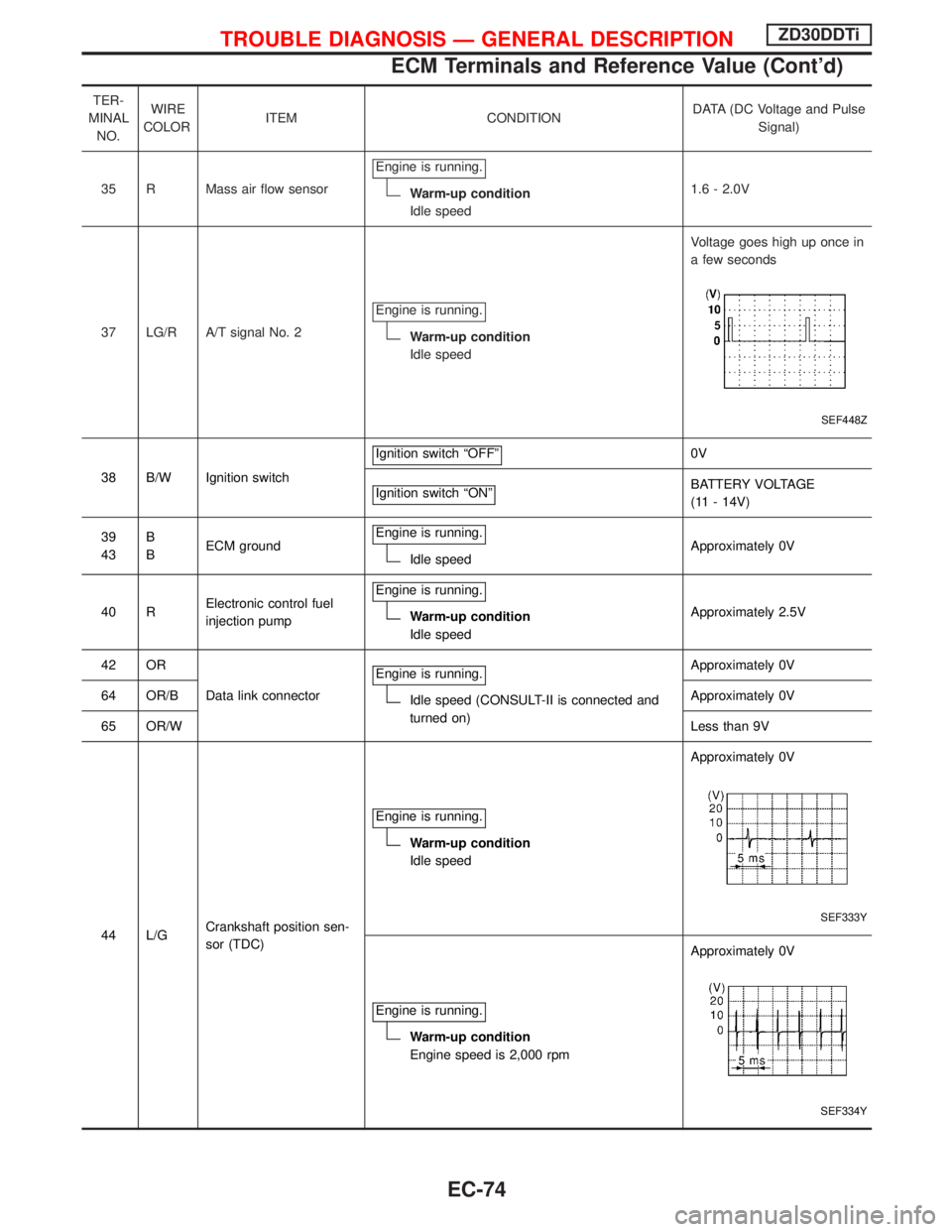
35 R Mass air flow sensorEngine is running.
Warm-up condition
Idle speed1.6 - 2.0V
37 LG/R A/T signal No. 2Engine is running.
Warm-up condition
Idle speedVoltage goes high up once in
a few seconds
SEF448Z
38 B/W Ignition switchIgnition switch ªOFFº
0V
Ignition switch ªONº
BATTERY VOLTAGE
(11 - 14V)
39
43B
BECM groundEngine is running.
Idle speedApproximately 0V
40 RElectronic control fuel
injection pumpEngine is running.
Warm-up condition
Idle speedApproximately 2.5V
42 OR
Data link connectorEngine is running.
Idle speed (CONSULT-II is connected and
turned on)Approximately 0V
64 OR/BApproximately 0V
65 OR/WLess than 9V
44 L/GCrankshaft position sen-
sor (TDC)Engine is running.
Warm-up condition
Idle speedApproximately 0V
SEF333Y
Engine is running.
Warm-up condition
Engine speed is 2,000 rpmApproximately 0V
SEF334Y
TROUBLE DIAGNOSIS Ð GENERAL DESCRIPTIONZD30DDTi
ECM Terminals and Reference Value (Cont'd)
EC-74
Page 437 of 1767
TER-
MINAL
NO.WIRE
COLORITEM CONDITIONDATA (DC Voltage and Pulse
Signal)
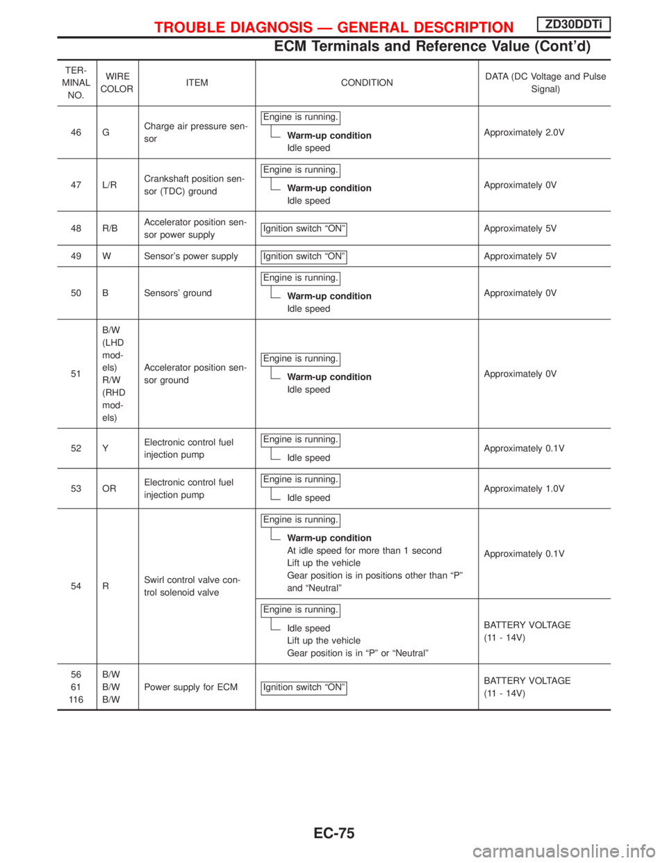
46 GCharge air pressure sen-
sorEngine is running.
Warm-up condition
Idle speedApproximately 2.0V
47 L/RCrankshaft position sen-
sor (TDC) groundEngine is running.
Warm-up condition
Idle speedApproximately 0V
48 R/BAccelerator position sen-
sor power supplyIgnition switch ªONº
Approximately 5V
49 W Sensor's power supply Ignition switch ªONº
Approximately 5V
50 B Sensors' groundEngine is running.
Warm-up condition
Idle speedApproximately 0V
51B/W
(LHD
mod-
els)
R/W
(RHD
mod-
els)Accelerator position sen-
sor groundEngine is running.
Warm-up condition
Idle speedApproximately 0V
52 YElectronic control fuel
injection pumpEngine is running.
Idle speedApproximately 0.1V
53 ORElectronic control fuel
injection pumpEngine is running.
Idle speedApproximately 1.0V
54 RSwirl control valve con-
trol solenoid valveEngine is running.
Warm-up condition
At idle speed for more than 1 second
Lift up the vehicle
Gear position is in positions other than ªPº
and ªNeutralºApproximately 0.1V
Engine is running.
Idle speed
Lift up the vehicle
Gear position is in ªPº or ªNeutralºBATTERY VOLTAGE
(11 - 14V)
56
61
11 6B/W
B/W
B/WPower supply for ECM Ignition switch ªONº
BATTERY VOLTAGE
(11 - 14V)
TROUBLE DIAGNOSIS Ð GENERAL DESCRIPTIONZD30DDTi
ECM Terminals and Reference Value (Cont'd)
EC-75
Page 440 of 1767
Description
Intermittent incidents (I/I) may occur. In many cases, the problem resolves itself (the part or circuit function
returns to normal without intervention). It is important to realize that the symptoms described in the custom-
er's complaint often do not recur on DTC visits. Realize also that the most frequent cause of I/I occurrences
is poor electrical connections. Because of this, the conditions under which the incident occurred may not be
clear. Therefore, circuit checks made as part of the standard diagnostic procedure may not indicate the spe-
cific problem area.
COMMON I/I REPORT SITUATIONS
STEP in Work Flow Situation
II The CONSULT-II is used. The SELF-DIAG RESULTS screen shows time data other than ª0º.
III The symptom described by the customer does not recur.
IV DTC does not appear during the DTC Confirmation Procedure.
VI The Diagnostic Procedure for XXXX does not indicate the problem area.
Diagnostic Procedure
1 INSPECTION START
Erase DTCs. Refer to ªHOW TO ERASE DTCº, EC-33.
EGO TO 2.
2 CHECK GROUND TERMINALS
Check ground terminals for corroding or loose connection.
Refer to GI section (ªGROUND INSPECTIONº, ªCircuit Inspectionº).
OK or NG
OKEGO TO 3.
NGERepair or replace.
3 SEARCH FOR ELECTRICAL INCIDENT
Perform GI section, ªIncident Simulation Testsº.
OK or NG
OKEINSPECTION END
NGERepair or replace.
TROUBLE DIAGNOSIS FOR INTERMITTENT INCIDENTZD30DDTi
EC-78
Page 450 of 1767
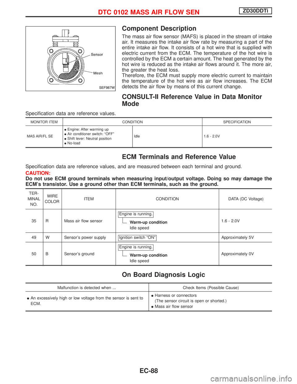
Component Description
The mass air flow sensor (MAFS) is placed in the stream of intake
air. It measures the intake air flow rate by measuring a part of the
entire intake air flow. It consists of a hot wire that is supplied with
electric current from the ECM. The temperature of the hot wire is
controlled by the ECM a certain amount. The heat generated by the
hot wire is reduced as the intake air flows around it. The more air,
the greater the heat loss.
Therefore, the ECM must supply more electric current to maintain
the temperature of the hot wire as air flow increases. The ECM
detects the air flow by means of this current change.
CONSULT-II Reference Value in Data Monitor
Mode
Specification data are reference values.
MONITOR ITEM CONDITION SPECIFICATION
MAS AIR/FL SEIEngine: After warming up
IAir conditioner switch: ªOFFº
IShift lever: Neutral position
INo-loadIdle 1.6 - 2.0V
ECM Terminals and Reference Value
Specification data are reference values, and are measured between each terminal and ground.
CAUTION:
Do not use ECM ground terminals when measuring input/output voltage. Doing so may damage the
ECM's transistor. Use a ground other than ECM terminals, such as the ground.
TER-
MINAL
NO.WIRE
COLORITEM CONDITION DATA (DC Voltage)
35 R Mass air flow sensorEngine is running.
Warm-up condition
Idle speed1.6 - 2.0V
49 W Sensor's power supply Ignition switch ªONº
Approximately 5V
50 B Sensor's groundEngine is running.
Warm-up condition
Idle speedApproximately 0V
On Board Diagnosis Logic
Malfunction is detected when ... Check Items (Possible Cause)
IAn excessively high or low voltage from the sensor is sent to
ECM.IHarness or connectors
(The sensor circuit is open or shorted.)
IMass air flow sensor
SEF987W
DTC 0102 MASS AIR FLOW SENZD30DDTi
EC-88
Page 471 of 1767
Description
SYSTEM DESCRIPTION
Sensor Input signal to ECM ECM function Actuator
Vehicle speed sensor Vehicle speed
Cooling fan con-
trolCooling fan relay Engine coolant temperature sensor Engine coolant temperature
Air conditioner switch Air conditioner ªONº signal
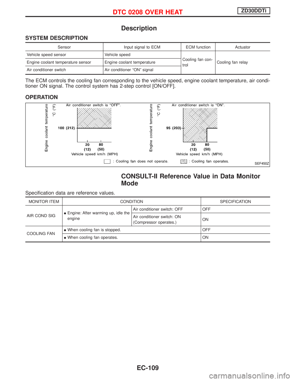
The ECM controls the cooling fan corresponding to the vehicle speed, engine coolant temperature, air condi-
tioner ON signal. The control system has 2-step control [ON/OFF].
OPERATION
CONSULT-II Reference Value in Data Monitor
Mode
Specification data are reference values.
MONITOR ITEM CONDITION SPECIFICATION
AIR COND SIGIEngine: After warming up, idle the
engineAir conditioner switch: OFF OFF
Air conditioner switch: ON
(Compressor operates.)ON
COOLING FANIWhen cooling fan is stopped. OFF
IWhen cooling fan operates. ON
SEF450Z
DTC 0208 OVER HEATZD30DDTi
EC-109
Page 477 of 1767
4 CHECK COOLING FAN POWER SUPPLY CIRCUIT
1. Turn ignition switch ªOFFº.
2. Disconnect cooling fan relay.
MEC021E
3. Turn ignition switch ªONº.
4. Turn air conditioner switch ªONº.
5. Turn blower fan switch ªONº.
6. Make sure that cooling fan operates.
7. Check voltage between cooling fan relay terminals 2, 3 and ground with CONSULT-II or tester.
MEC974DVoltage: Battery voltage
OK or NG
OKEGO TO 6.
NGEGO TO 5.
5 DETECT MALFUNCTIONING PART
Check the following.
I10A fuse
IHarness connector F120, M812 (LHD models)
IA/C relay
I30A fusible links
IHarness for open or short between cooling fan relay and fuse
IHarness for open or short between cooling fan relay and battery
ERepair open circuit or short to ground or short to power in harness or connectors.
DTC 0208 OVER HEATZD30DDTi
Diagnostic Procedure (Cont'd)
EC-115
Page 503 of 1767
13 CHECK ACCELERATOR POSITION SWITCH INPUT SIGNAL CIRCUIT-I FOR OPEN AND SHORT
1. Turn ignition switch ªOFFº.
2. Disconnect ECM harness connector.
3. Check harness continuity between accelerator position switch terminal 6 and ECM terminal 31. Refer to Wiring Diagram.
Continuity should exist.
4. Also check harness for short to ground and short to power.
OK or NG
OKEGO TO 14.
NGERepair open circuit or short to ground or short to power in harness or connectors.
14 CHECK ACCELERATOR POSITION SWITCH INPUT SIGNAL CIRCUIT-II FOR OPEN AND SHORT
1. Check harness continuity between accelerator position switch terminal 4 and ECM terminal 32. Refer to Wiring Diagram.
Continuity should exist.
2. Also check harness for short to ground and short to power.
OK or NG
OKEGO TO 15.
NGERepair open circuit or short to ground or short to power in harness or connectors.
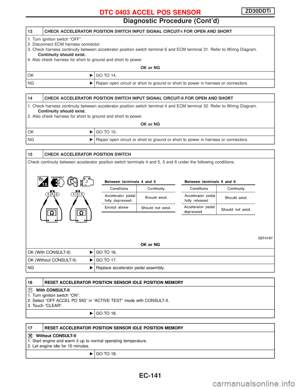
15 CHECK ACCELERATOR POSITION SWITCH
Check continuity between accelerator position switch terminals 4 and 5, 5 and 6 under the following conditions.
SEF418Y
OK or NG
OK (With CONSULT-II)EGO TO 16.
OK (Without CONSULT-II)EGO TO 17.
NGEReplace accelerator pedal assembly.
16 RESET ACCELERATOR POSITION SENSOR IDLE POSITION MEMORY
With CONSULT-II
1. Turn ignition switch ªONº.
2. Select ªOFF ACCEL PO SIGº in ªACTIVE TESTº mode with CONSULT-II.
3. Touch ªCLEARº.
EGO TO 18.
17 RESET ACCELERATOR POSITION SENSOR IDLE POSITION MEMORY
Without CONSULT-II
1. Start engine and warm it up to normal operating temperature.
2. Let engine idle for 10 minutes.
EGO TO 18.
DTC 0403 ACCEL POS SENSORZD30DDTi
Diagnostic Procedure (Cont'd)
EC-141