2002 NISSAN TERRANO air condition
[x] Cancel search: air conditionPage 112 of 1767
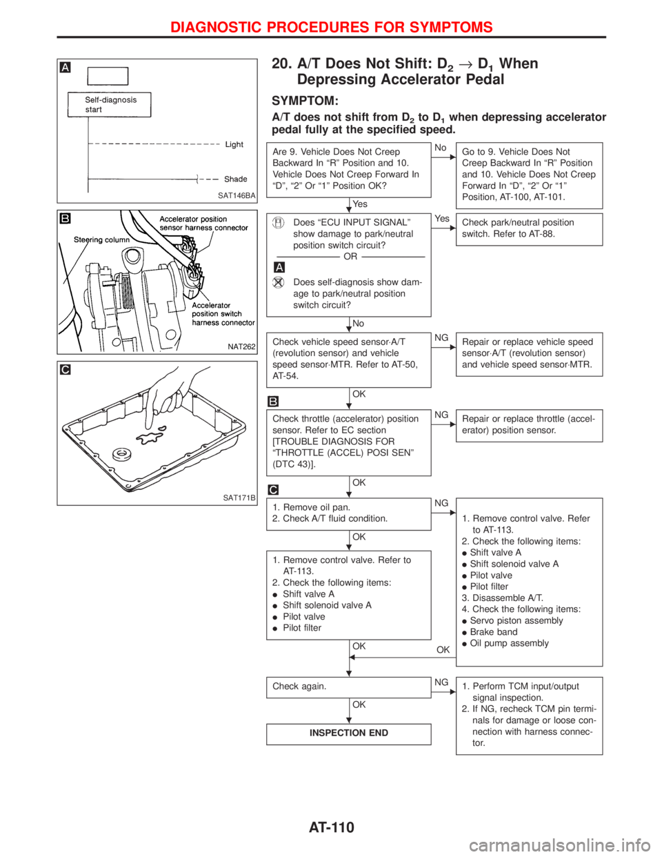
20. A/T Does Not Shift: D2®D1When
Depressing Accelerator Pedal
SYMPTOM:
A/T does not shift from D2to D1when depressing accelerator
pedal fully at the specified speed.
Are 9. Vehicle Does Not Creep
Backward In ªRº Position and 10.
Vehicle Does Not Creep Forward In
ªDº, ª2º Or ª1º Position OK?
Ye s
ENo
Go to 9. Vehicle Does Not
Creep Backward In ªRº Position
and 10. Vehicle Does Not Creep
Forward In ªDº, ª2º Or ª1º
Position, AT-100, AT-101.
Does ªECU INPUT SIGNALº
show damage to park/neutral
position switch circuit?
-----------------------------------------------------------------------------------------------------OR -----------------------------------------------------------------------------------------------------
Does self-diagnosis show dam-
age to park/neutral position
switch circuit?
No
EYe s
Check park/neutral position
switch. Refer to AT-88.
Check vehicle speed sensor×A/T
(revolution sensor) and vehicle
speed sensor×MTR. Refer to AT-50,
AT-54.
OK
ENG
Repair or replace vehicle speed
sensor×A/T (revolution sensor)
and vehicle speed sensor×MTR.
Check throttle (accelerator) position
sensor. Refer to EC section
[TROUBLE DIAGNOSIS FOR
ªTHROTTLE (ACCEL) POSI SENº
(DTC 43)].
OK
ENG
Repair or replace throttle (accel-
erator) position sensor.
1. Remove oil pan.
2. Check A/T fluid condition.
OK
ENG
1. Remove control valve. Refer
to AT-113.
2. Check the following items:
IShift valve A
IShift solenoid valve A
IPilot valve
IPilot filter
3. Disassemble A/T.
4. Check the following items:
IServo piston assembly
IBrake band
IOil pump assembly
1. Remove control valve. Refer to
AT-113.
2. Check the following items:
IShift valve A
IShift solenoid valve A
IPilot valve
IPilot filter
OKFOK
Check again.
OK
ENG
1. Perform TCM input/output
signal inspection.
2. If NG, recheck TCM pin termi-
nals for damage or loose con-
nection with harness connec-
tor.
INSPECTION END
SAT146BA
NAT262
SAT171B
H
H
H
H
H
H
H
DIAGNOSTIC PROCEDURES FOR SYMPTOMS
AT-110
Page 215 of 1767
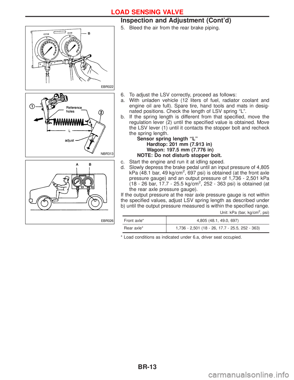
5. Bleed the air from the rear brake piping.
6. To adjust the LSV correctly, proceed as follows:
a. With unladen vehicle (12 liters of fuel, radiator coolant and
engine oil are full). Spare tire, hand tools and mats in desig-
nated positions. Check the length of LSV spring ªLº.
b. If the spring length is different from that specified, move the
regulation lever (2) until the specified value is obtained. Move
the LSV lever (1) until it contacts the stopper bolt and recheck
the spring length.
Sensor spring length ªLº
Hardtop: 201 mm (7.913 in)
Wagon: 197.5 mm (7.776 in)
NOTE: Do not disturb stopper bolt.
c. Start the engine and run it at idling speed.
d. Slowly depress the brake pedal until an input pressure of 4,805
kPa (48.1 bar, 49 kg/cm
2, 697 psi) is obtained (at the front axle
pressure gauge) and an output pressure of 1,736 - 2,501 kPa
(18 - 26 bar, 17.7 - 25.5 kg/cm
2, 252 - 363 psi) is obtained (at
the rear axle pressure gauge).
If the output pressure at the rear axle pressure gauge is not within
the specified values, adjust LSV spring length as described under
b) until the output pressure measured is within the specified range.
Unit: kPa (bar, kg/cm2, psi)
Front axle* 4,805 (48.1, 49.0, 697)
Rear axle* 1,736 - 2,501 (18 - 26, 17.7 - 25.5, 252 - 363)
* Load conditions as indicated under 6.a, driver seat occupied.
EBR022
NBR313
EBR026
LOAD SENSING VALVE
Inspection and Adjustment (Cont'd)
BR-13
Page 218 of 1767
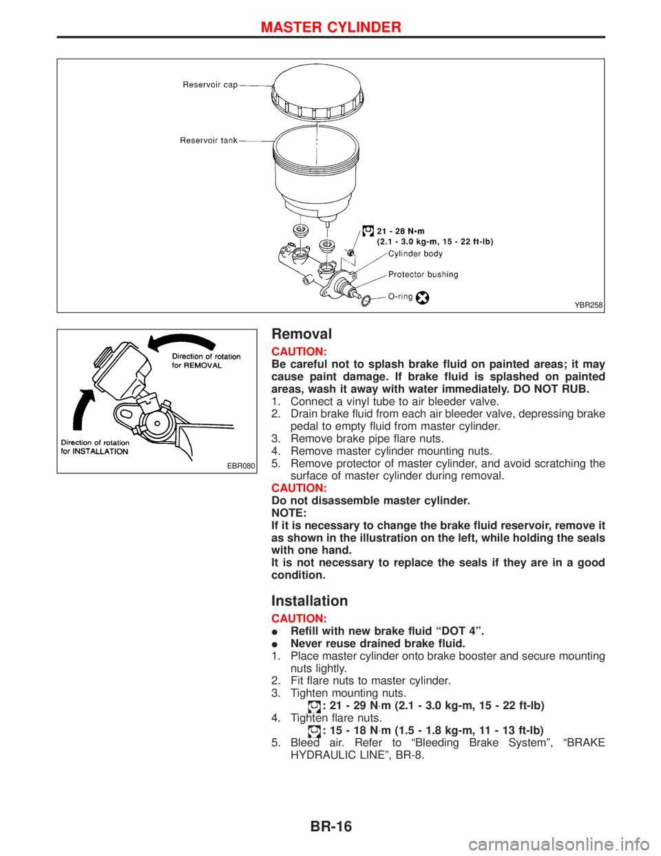
Removal
CAUTION:
Be careful not to splash brake fluid on painted areas; it may
cause paint damage. If brake fluid is splashed on painted
areas, wash it away with water immediately. DO NOT RUB.
1. Connect a vinyl tube to air bleeder valve.
2. Drain brake fluid from each air bleeder valve, depressing brake
pedal to empty fluid from master cylinder.
3. Remove brake pipe flare nuts.
4. Remove master cylinder mounting nuts.
5. Remove protector of master cylinder, and avoid scratching the
surface of master cylinder during removal.
CAUTION:
Do not disassemble master cylinder.
NOTE:
If it is necessary to change the brake fluid reservoir, remove it
as shown in the illustration on the left, while holding the seals
with one hand.
It is not necessary to replace the seals if they are in a good
condition.
Installation
CAUTION:
IRefill with new brake fluid ªDOT 4º.
INever reuse drained brake fluid.
1. Place master cylinder onto brake booster and secure mounting
nuts lightly.
2. Fit flare nuts to master cylinder.
3. Tighten mounting nuts.
:21-29N×m (2.1 - 3.0 kg-m, 15 - 22 ft-lb)
4. Tighten flare nuts.
:15-18N×m (1.5 - 1.8 kg-m, 11 - 13 ft-lb)
5. Bleed air. Refer to ªBleeding Brake Systemº, ªBRAKE
HYDRAULIC LINEº, BR-8.
YBR258
EBR080
MASTER CYLINDER
BR-16
Page 223 of 1767
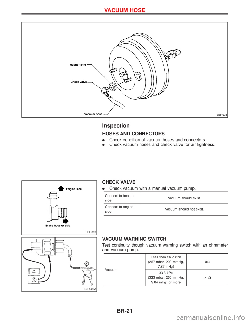
Inspection
HOSES AND CONNECTORS
ICheck condition of vacuum hoses and connectors.
ICheck vacuum hoses and check valve for air tightness.
CHECK VALVE
ICheck vacuum with a manual vacuum pump.
Connect to booster
sideVacuum should exist.
Connect to engine
sideVacuum should not exist.
VACUUM WARNING SWITCH
Test continuity though vacuum warning switch with an ohmmeter
and vacuum pump.
VacuumLess than 26.7 kPa
(267 mbar, 200 mmHg,
7.87 inHg)0W
33.3 kPa
(333 mbar, 250 mmHg,
9.84 inHg) or more
W
EBR008
EBR009
SBR007A
VACUUM HOSE
BR-21
Page 249 of 1767
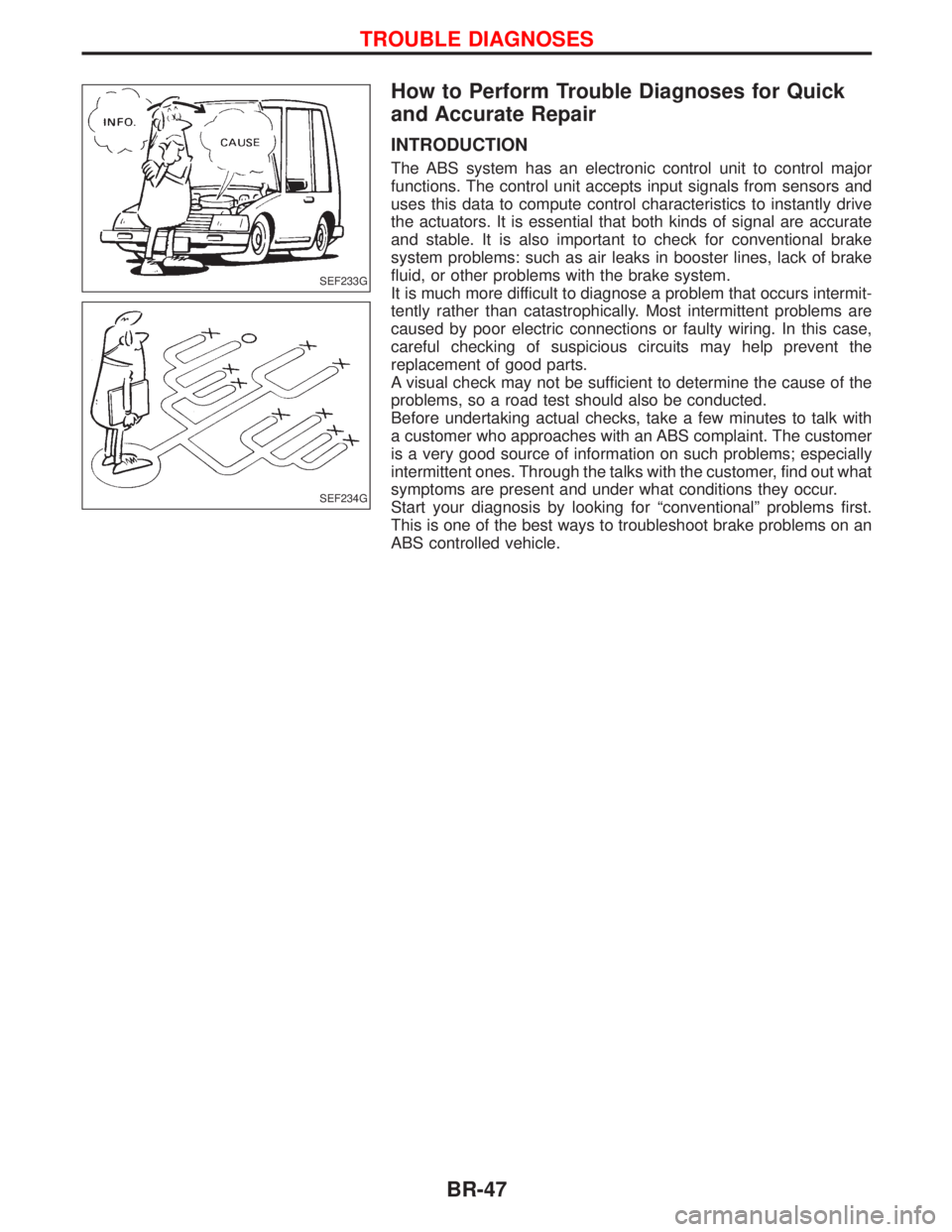
How to Perform Trouble Diagnoses for Quick
and Accurate Repair
INTRODUCTION
The ABS system has an electronic control unit to control major
functions. The control unit accepts input signals from sensors and
uses this data to compute control characteristics to instantly drive
the actuators. It is essential that both kinds of signal are accurate
and stable. It is also important to check for conventional brake
system problems: such as air leaks in booster lines, lack of brake
fluid, or other problems with the brake system.
It is much more difficult to diagnose a problem that occurs intermit-
tently rather than catastrophically. Most intermittent problems are
caused by poor electric connections or faulty wiring. In this case,
careful checking of suspicious circuits may help prevent the
replacement of good parts.
A visual check may not be sufficient to determine the cause of the
problems, so a road test should also be conducted.
Before undertaking actual checks, take a few minutes to talk with
a customer who approaches with an ABS complaint. The customer
is a very good source of information on such problems; especially
intermittent ones. Through the talks with the customer, find out what
symptoms are present and under what conditions they occur.
Start your diagnosis by looking for ªconventionalº problems first.
This is one of the best ways to troubleshoot brake problems on an
ABS controlled vehicle.
SEF233G
SEF234G
TROUBLE DIAGNOSES
BR-47
Page 282 of 1767

Diagnostic Procedure 10 (Pedal vibration and
noise)
INSPECTION START
1. Apply brake.
2. Start engine.
3. Does the symptom appear only when
engine is started?
No
EYe s
Carry out self-diagnosis.
Refer to BR-59.
CHECK IF SYMPTOM APPEARS.
Does the symptom appear when electrical
equipment switches (such as headlamp)
are operated?
Ye s
ENo
Go toin Diagnostic
Procedure 12, BR-81.
CHECK WHEEL SENSOR.
Check wheel sensor shield ground. For
location of shield ground, refer to wiring
diagram and ªHARNESS LAYOUTº in EL
section.
OK
ENG
Repair wheel sensor.
CHECK HARNESS CONNECTOR.
Check ABS actuator and electric unit pin
terminals for damage or the connection of
ABS actuator and electric unit harness
connector.
Reconnect ABS actuator and electric unit
harness connector. Then retest.
Note: ABS may operate and cause vibration under any of the
following conditions.
Diagnostic Procedure 11 (Long stopping
distance)
CHECK ABS PERFORMANCE
Disconnect ABS actuator and electric unit
connector and check whether stopping
distance is still long.
Ye s
ENo
Go toin Diagnostic
Procedure 12, BR-81.
Perform Preliminary Check and air bleed-
ing.
Note: Stopping distance may be larger than vehicles without
ABS when road condition is slippery.
SAT797AH
H
H
H
TROUBLE DIAGNOSES
BR-80
Page 293 of 1767
Checking Body Corrosion
Visually check the body sheet metal panel for corrosion, paint damage (scratches, chipping, rubbing, etc.) or
damage to the anti-corrosion materials. In particular, check the following locations.
Hemmed portion
Hood front end, door lower end, back door rear end, etc.
Panel joint
Side sill of rear fender and center pillar, rear wheel housing of rear fender, around strut tower in engine
compartment, etc.
Panel edge
Back door opening, sunroof opening, fender wheelarch flange, fuel filler lid flange, around holes in panel, etc.
Parts contact
Waist molding, windshield molding, bumper, etc.
Protectors
Damage or condition of mudguard, fender protector, chipping protector, etc.
Anti-corrosion materials
Damage or separation of anti-corrosion materials under the body.
Drain holes
Condition of drain holes at door and side sill.
When repairing corroded areas, refer to the Corrosion Repair Manual.
CHASSIS AND BODY MAINTENANCE
BT-5
Page 363 of 1767
ENGINE CONTROL SYSTEM
SECTION
EC
CONTENTS
ZD30DDTi
TROUBLE DIAGNOSIS - INDEX....................................7
Alphabetical & Numerical Index for DTC ....................7
PRECAUTIONS...............................................................9
Precautions ..................................................................9
ENGINE AND EMISSION CONTROL OVERALL
SYSTEM.........................................................................12
Engine Control Component Parts Location ...............12
Circuit Diagram ..........................................................16
System Diagram ........................................................17
Vacuum Hose Drawing ..............................................18
System Chart .............................................................19
ENGINE AND EMISSION BASIC CONTROL
SYSTEM DESCRIPTION...............................................20
Fuel Injection Control System ...................................20
Fuel Injection Timing Control System........................22
Air Conditioning Cut Control ......................................22
Fuel Cut Control (at no load & high engine
speed) ........................................................................22
Crankcase Ventilation System ...................................23
BASIC SERVICE PROCEDURE...................................24
Injection Tube and Injection Nozzle ..........................24
Electronic Control Fuel Injection Pump .....................27
Air Bleeding ...............................................................32
ON BOARD DIAGNOSTIC SYSTEM
DESCRIPTION...............................................................33
DTC and MI Detection Logic .....................................33
Diagnostic Trouble Code (DTC) ................................33
Malfunction Indicator (MI) ..........................................34
CONSULT-II ...............................................................39
TROUBLE DIAGNOSIS - INTRODUCTION..................46
Introduction ................................................................46
Work Flow ..................................................................48
TROUBLE DIAGNOSIS - BASIC INSPECTION...........50
Basic Inspection.........................................................50
TROUBLE DIAGNOSIS - GENERAL
DESCRIPTION...............................................................56
Symptom Matrix Chart ...............................................56CONSULT-II Reference Value in Data Monitor
Mode ..........................................................................66
Major Sensor Reference Graph in Data Monitor
Mode ..........................................................................68
ECM Terminals and Reference Value .......................69
TROUBLE DIAGNOSIS FOR INTERMITTENT
INCIDENT.......................................................................78
Description .................................................................78
Diagnostic Procedure ................................................78
TROUBLE DIAGNOSIS FOR POWER SUPPLY..........79
Main Power Supply and Ground Circuit ....................79
DTC 0102 MASS AIR FLOW SEN................................88
Component Description .............................................88
CONSULT-II Reference Value in Data Monitor
Mode ..........................................................................88
ECM Terminals and Reference Value .......................88
On Board Diagnosis Logic.........................................88
DTC Confirmation Procedure ....................................89
Wiring Diagram ..........................................................90
Diagnostic Procedure ................................................92
DTC 0103 COOLANT TEMP SEN................................95
Description .................................................................95
On Board Diagnosis Logic.........................................95
DTC Confirmation Procedure ....................................95
Wiring Diagram ..........................................................96
Diagnostic Procedure ................................................97
DTC 0104 VEHICLE SPEED SEN................................99
Description .................................................................99
ECM Terminals and Reference Value .......................99
On Board Diagnosis Logic.........................................99
Overall Function Check ...........................................100
Wiring Diagram ........................................................101
Diagnostic Procedure ..............................................103
DTC 0203 ACCEL POS SW (F/C)..............................104
Description ...............................................................104
CONSULT-II Reference Value in Data Monitor
Mode ........................................................................104
ECM Terminals and Reference Value .....................104
On Board Diagnosis Logic.......................................104