Page 1873 of 2100
METER AND GAUGE8E±7
A/T Shift Indicator Light Bulb
Removal
1. Disconnect the battery ground cable.
2. Pry up the bended portions(2) of the metal cover(1).
821RY00060
Page 1875 of 2100
METER AND GAUGE8E±9
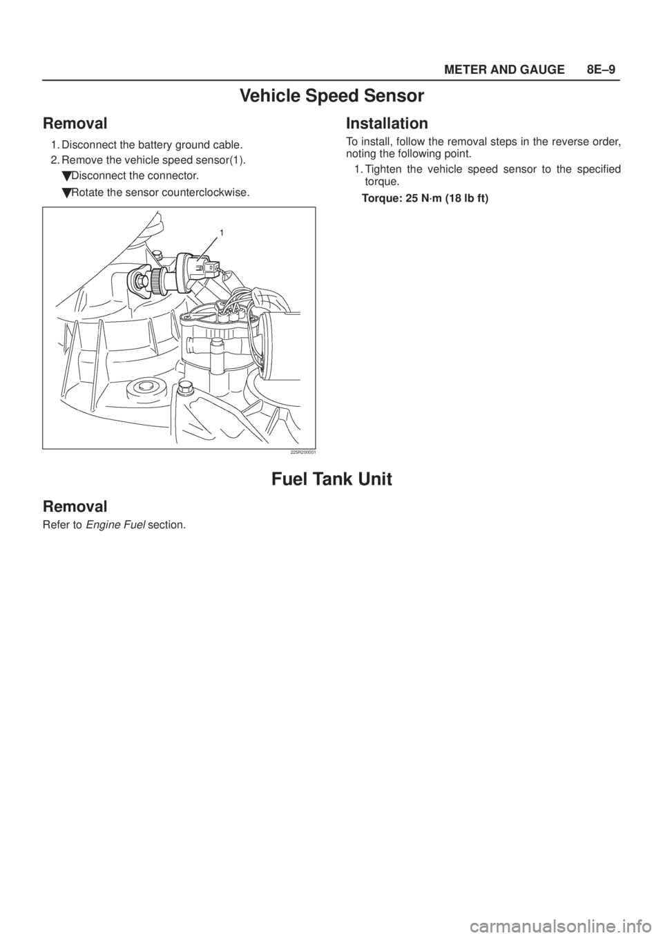
Vehicle Speed Sensor
Removal
1. Disconnect the battery ground cable.
2. Remove the vehicle speed sensor(1).
�Disconnect the connector.
�Rotate the sensor counterclockwise.
225R200001
Installation
To install, follow the removal steps in the reverse order,
noting the following point.
1. Tighten the vehicle speed sensor to the specified
torque.
Torque: 25 N´m (18 lb ft)
Fuel Tank Unit
Removal
Refer to Engine Fuel section.
Page 1881 of 2100
8F±5 BODY STRUCTURE
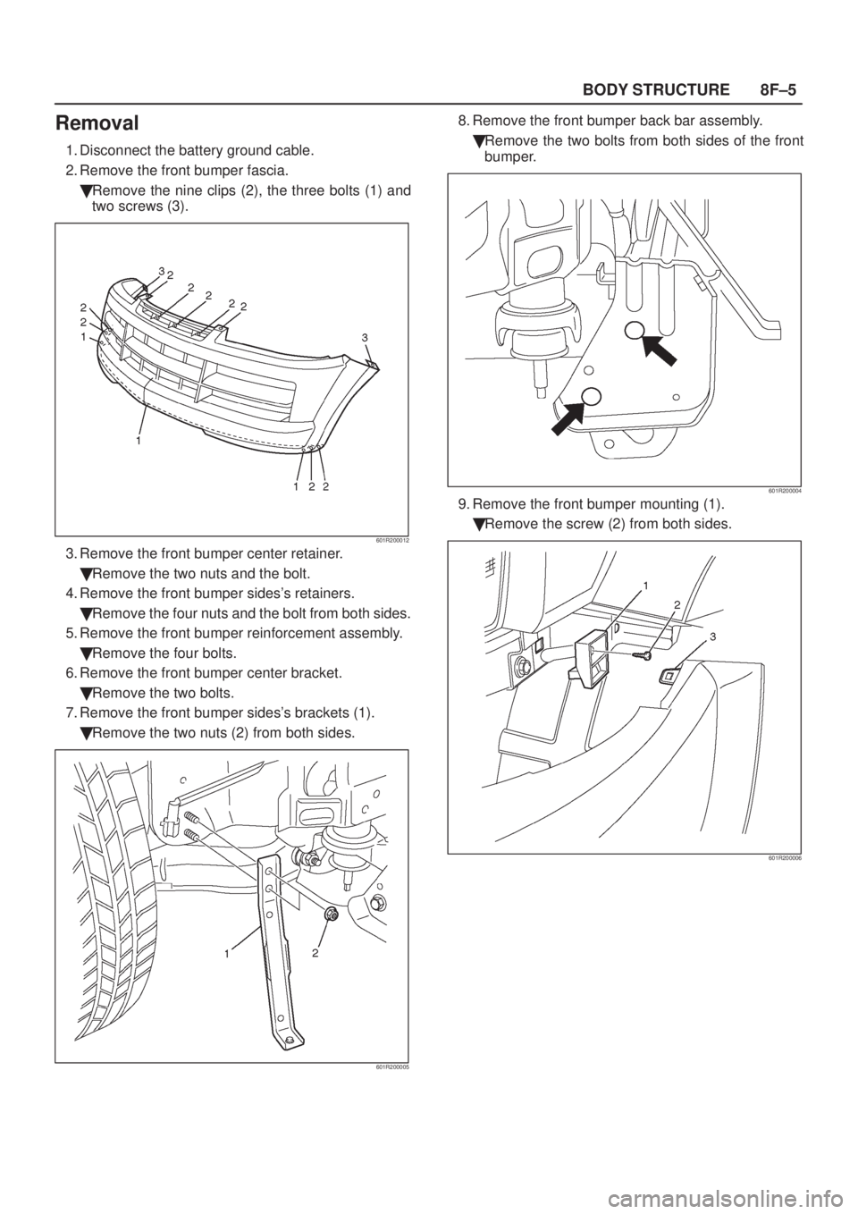
Removal
1. Disconnect the battery ground cable.
2. Remove the front bumper fascia.
�Remove the nine clips (2), the three bolts (1) and
two screws (3).
601R200012
3. Remove the front bumper center retainer.
�Remove the two nuts and the bolt.
4. Remove the front bumper sides's retainers.
�Remove the four nuts and the bolt from both sides.
5. Remove the front bumper reinforcement assembly.
�Remove the four bolts.
6. Remove the front bumper center bracket.
�Remove the two bolts.
7. Remove the front bumper sides's brackets (1).
�Remove the two nuts (2) from both sides.
601R200005
8. Remove the front bumper back bar assembly.
�Remove the two bolts from both sides of the front
bumper.
601R200004
9. Remove the front bumper mounting (1).
�Remove the screw (2) from both sides.
601R200006
Page 1884 of 2100
8F±8BODY STRUCTURE
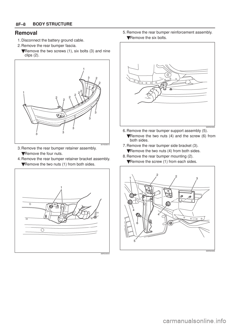
Removal
1. Disconnect the battery ground cable.
2. Remove the rear bumper fascia.
�Remove the two screws (1), six bolts (3) and nine
clips (2).
601R200010
3. Remove the rear bumper retainer assembly.
�Remove the four nuts.
4. Remove the rear bumper retainer bracket assembly.
�Remove the two nuts (1) from both sides.
690R200004
5. Remove the rear bumper reinforcement assembly.
�Remove the six bolts.
690R200005
6. Remove the rear bumper support assembly (5).
�Remove the two nuts (4) and the screw (6) from
both sides.
7. Remove the rear bumper side bracket (3).
�Remove the two nuts (4) from both sides.
8. Remove the rear bumper mounting (2).
�Remove the screw (1) from each sides.
690R200009
Page 1892 of 2100
8F±16BODY STRUCTURE
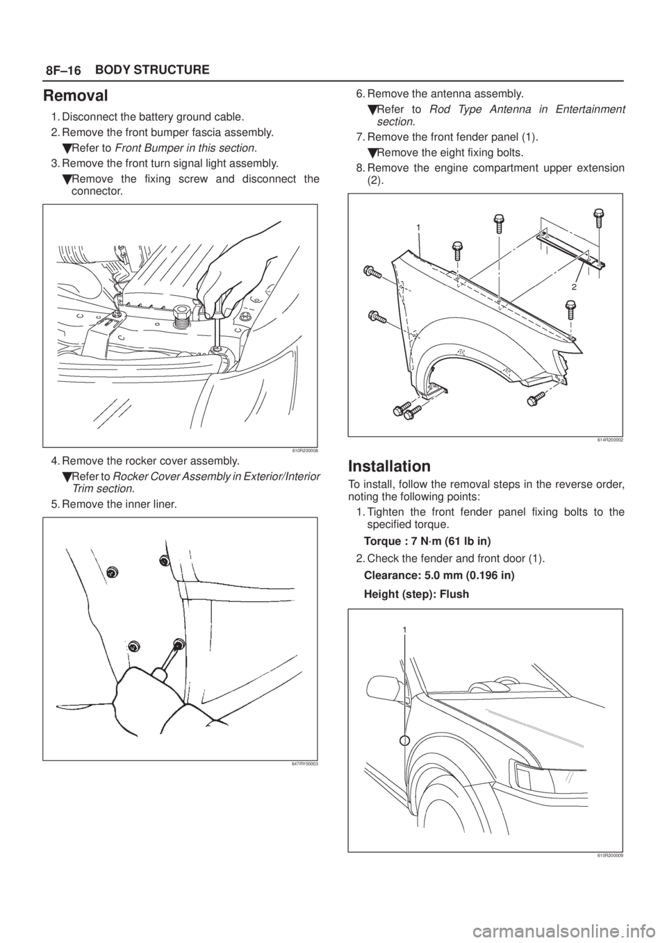
Removal
1. Disconnect the battery ground cable.
2. Remove the front bumper fascia assembly.
�Refer to
Front Bumper in this section.
3. Remove the front turn signal light assembly.
�Remove the fixing screw and disconnect the
connector.
610R200008
4. Remove the rocker cover assembly.
�Refer to
Rocker Cover Assembly in Exterior/Interior
Trim section.
5. Remove the inner liner.
647RY00003
6. Remove the antenna assembly.
�Refer to
Rod Type Antenna in Entertainment
section.
7. Remove the front fender panel (1).
�Remove the eight fixing bolts.
8. Remove the engine compartment upper extension
(2).
614R200002
Installation
To install, follow the removal steps in the reverse order,
noting the following points:
1. Tighten the front fender panel fixing bolts to the
specified torque.
Torque : 7 N´m (61 lb in)
2. Check the fender and front door (1).
Clearance: 5.0 mm (0.196 in)
Height (step): Flush
610R200009
Page 1909 of 2100
 ± AIR BAG in
Restraint section.
1. Disconn")
8F±33 BODY STRUCTURE
Removal
CAUTION: F o r p recautions on installation or
removal of SRS ± air bag system, refer to
Supplemental Restraint System (SRS) ± AIR BAG in
Restraint section.
1. Disconnect the battery ground cable.
2. Pry the knee pads (4).
3. Remove the cluster upper cover (1) and connectors.
4. Remove the center cluster assembly (2).
�Remove six screws and pull out the cluster at the six
clip positions.
�Disconnect the cigarette lighter (6), ash tray (5)
illumination and hazard switch (3) connectors.
740R200008
5. Remove the display unit.
�Remove the four fixing screws and connectors.
6. Remove the audio kit.
�Remove the four fixing screws and connectors.
7. Remove the front and rear consoles.
�Refer to
Consoles in Exterior/Interior Trim section.
8. Remove the dash side trim panels.
�Remove the sill plates, then remove the trim panels.
9. Remove the glove box.
�Remove the two fixing screws.
470RW002
10. Remove the instrument panel driver lower cover
assembly.
�Remove the engine hood opener two fixing screws
and another one fixing screw.
After four clips are pried, disconnect switch
connector and duct.
610R200007
11. Remove the meter cluster assembly.
�Remove the six fixing screws and switch
connectors.
12. Remove the meter assembly.
�Remove the four fixing screws and disconnect the
connectors.
13. Remove the driver knee bolster assembly.
�Remove the six fixing bolts and screw.
14. Remove the instrument panel assembly.
CAUTION: F o r p recautions on installation or
removal of SRS ± air bag system, refer to
Supplemental Restraint System (SRS) ± AIR BAG in
Restraint section.
Page 1911 of 2100
8F±35 BODY STRUCTURE
Front Door Assembly
Parts Location
630R200010
Legend
(1) Front Door Assembly
(2) Upper Hinge Bolt(3) Door Harness Connector
(4) Door Check Arm
(5) Lower Hinge Bolt
Removal
1. Disconnect the battery ground cable.
2. Apply a setting mark on the body side hinge.
3. Remove the door check arm bolt.
630R200011
Page 1913 of 2100
8F±37 BODY STRUCTURE
Rear Door Assembly
Parts Location
650R200001
Legend
(1) Rear Door Assembly
(2) Lower Hinge Bolt(3) Door Check Arm
(4) Door Harness Connector
(5) Upper Hinge Bolt
Removal
1. Disconnect the battery ground cable.
2. Apply a setting mark on the body side hinge.
3. Remove the door check arm bolt.
650R200002
4. Remove the upper and lower hinge bolts.
�Position a wood block under the door for protection
and support the door assembly with hands during
removal or installation.
650R200004
 of the metal cover(1).
821RY00060")
 Front Door Assembly
(2) Upper Hinge Bolt(3) Door Harness Connector
(4) Door Check Arm
(5) Lower Hinge Bolt
Removal
1. Dis")
 Rear Door Assembly
(2) Lower Hinge Bolt(3) Door Check Arm
(4) Door Harness Connector
(5) Upper Hinge Bolt
Removal
1. Disco")